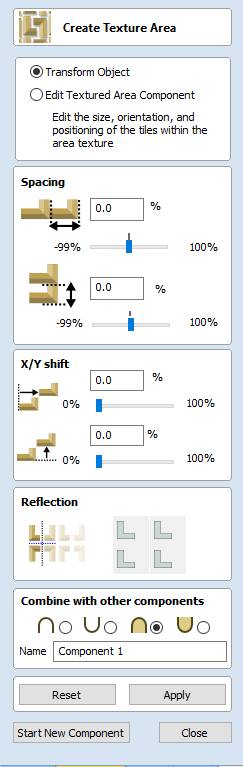
Create Texture Area

The Create Texture Area tool assists in the creation of components with a repeating pattern or texture. It requires a single component and optionally one or more closed boundary vectors which define the region in which the tiling should take place.
The Create Texture Area form is accessed from the modelling tab.
The first step is to select the component you wish to be tiled. If you want to restrict the tiling to a region then you should also select one or more closed vectors which will represent the boundary when the texture is created. If no boundary vector is selected then the tiling will fill the entire job space.
The Create Texture Area form contains options to adjust the spacing, overlap, positioning and symmetry of the texture which are discussed below. When you click the button then the software will create a Component based on the settings in the form and any vector you may have selected for the boundary.
At this moment the original selected Component will be made invisible to avoid confusion with what you can see in the 3D View.
Once you click Apply then this will effective fix the basic outline or silhouette of your Texture Area either based on the selected vector or the job area. It is possible to edit the size, position and rotation of this but if you wanted to change to a different border shape then you would need to start again with a new selection.
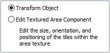
By default the form has Transform Object selected at the top. In this mode you can click on the Texture Area Component and use the drag-handles to move, scale or rotate it. Note that this will not change the size of your Tile (original seed Component). To change the size of the Tile you would use the Edit Textured Area Component option which is covered further down in this document.
Spacing
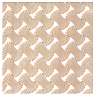
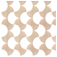
The spacing edit box or sliders can be used to control the degree of spacing between the tiles in a pattern component. You can adjust the spacing between the components horizontally and/or vertically. The amount of horizontal spacing is given in terms of a percentage of the width of the tile component. The amount of vertical spacing is given in terms of a percentage of the height of it. To control the amount of spacing, use the two sliders in the box marked Spacing. Drag and release the slider to set the percentage, or alternatively type an exact amount into the edit box above and either hit or press the Space bar on the keyboard to update the result. You can enter both positive and negative values. Positive spacing values open gaps between the objects in the texture and negative spacing has the opposite effect making the tiles overlap one another as shown below.
Shape with 25% X and 25% Y spacing
Shape with -25% X and -25% Y spacing
Translation : X/Y Shift
The X/Y shift option can be used to move all the tiles in alternate rows horizontally or alternate columns vertically by the specified amount. As with the spacing, the X/Y shift is given as a percentage of the size of the component in the appropriate dimension and can be adjusted using either the sliders or the edit boxes. For example entering a shift value of 50% horizontally (X) would move the second row over by half the width of the object, the third row would be as the first, then the fourth shifted, this shift would also be applied to every other row after that within the Textured Area. Similarly entering a value of 50% for the vertical shift (Y) will move every other column up by half the height of the object.
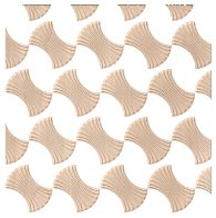
Shape with 50% X shift

Shape with 50% Y shift
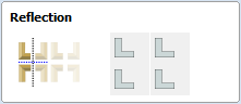
Reflection
The reflection tool consists of four buttons. Each button represents one tile in a mini-group of four, starting from the lower left copy which is represented by the original Tile. Each button has 4 states of reflection, each time the button is clicked, the icon representing the button will change to show the current state. Click to update the Texture Area Component with your new choice.

No reflection

Horizontal reflection

Vertical reflection

Both horizontal and vertical reflection
The following diagram shows the results of a few different choices:

No reflections (Default)

Resulting Pattern

No Reflections on the Bottom Row,
Horizontal Reflections on the Top Row
Resulting Pattern

All Options Reflecting Each Other
Resulting Pattern
Editing an Existing Texture Area
When you have created a pattern you can edit the size of the individual Tile component you are creating a pattern from by selecting the Edit Textured Area Component option at the top of the form. Within the 2D View this will then put an orange transform box around the lower left component in the pattern. You can alter the size of this by left clicking on one of the handles and dragging it to size, when you let go this will update the pattern to fit the new size within the Texture Area boundary. You can also move the location of this Tile by clicking the center node and dragging it with the mouse to a new location. This again will change the layout of the pattern.
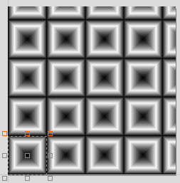
Pattern in Edit Texture Area Component
Transform Box Appears
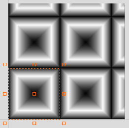
Pull handle on Transform Box to Alter Size
and the Pattern Updates to the New Size
A Texture Area component will remember that it is in a special state and not a standard component. This means that they can be further edited using the Texture Area form even after Closing and re-entering the function. To edit an existing Texture Area component, select it and then open the Create Texture Area tool. Alternatively, open the Create Texture Area tool and then select the existing component. This will then let you continue to make changes to it using the form.
Once a Texture Area Component has been Baked it is not possible to edit using the Create Texture Area form, it will just become a standard Component.
A Texture Area Component will retain the fact it is a Texture Area if exported as a 3DClip file and imported into another session of Aspire.
It can also be copied and pasted between sessions.
In either case it can then be edited using the Texture Area Component forum until Baked.
Resizing
Texture Area components do not behave like standard components when they are scaled in X or Y. When a Texture Area component is resized, then this resizes the boundary in which the tiling takes place so the size of the individual Tiles will not change, just the area that they are covering will be updated.
Typical baked component resize - shapes scale
Texture component resize - shapes do not scale
Common Modeling Options
All of the main modeling tools in the software use a common set of commands to assign a name and combine mode to the component being created along with options to apply the settings in the form, reset the shape, start creating a new component and close to exit the function.
Combine with other components...
This section includes options to allow you to name your Component and control the way it will be combined with other objects in the Component Tree.
Reset
Clicking the button will remove the current shape, doing this before you Close the form will ensure that a component is not created from the current selection. Clicking this does retain the current set of selected vectors or Components.
Apply
Clicking the button will create a shape based on the settings you have chosen. You can continue making edits to the component by choosing different parameters within the form and hitting to update it.
Start New Component
Clicking the button will save the state of the component that has been created, deselect all components/vectors and start the creation process again on a new component. The values and options within the form will be retained in this case until you Close it.
Close
Clicking the button will close the form returning to the Modeling Tab icons and the updated Component Tree reflecting any changes that you have made. If you wanted to remove the shape you just created then you can hit the Undo icon or use the keyboard shortcut to undo, CTRL+Z.
Texture Area Clipart
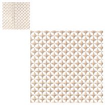
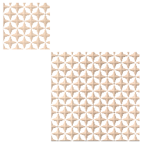
Aspire is supplied with 40+ Clipart files designed to be used with the Texture Area tool, for a new installation of the program these can be download from the Vectric Customer Portal and once installed will appear in a folder called Texture Area Tiles in the Clipart Tab. These mainly fall into two types of shape, those that go to the edge of the square and those that don't. The ones that go to the edge of the square tile area (eg. Block Wall 1) are designed to be tiled seamlessly so you would not typically use the modifying options in the form when working with these for spacing, overlap or Shift but you may want to change the size of the tile using the Edit Textured Area Component option. The shapes that don't got to the edge (eg. Diamond Plate 1) are designed to be manipulated with the modifying options on the form to achieve different results:
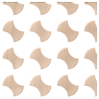
Diamond Plate 1
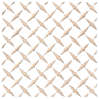
Diamond Plate 1 Pattern
-33.3% X Space, +33.3% Y Space
50% Y Shift - Right hand tiles mirrored
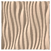
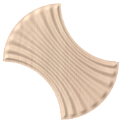
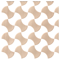
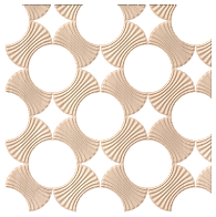
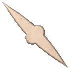
Wave Tile 2
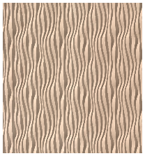
Wave Tile 2 Pattern
No spacing, shift or mirror
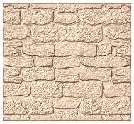
Block Wall 1
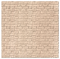
Block Wall 1 Pattern
No spacing shift or mirror