
Cut2D Desktop User Manual

Version 9
Click on the region of the interface you are interested in:
|

|

|
Disclaimer
All CNC machines (routing, engraving, and milling) are potentially dangerous and because Vectric Ltd. has no control over how the software described in this manual might be used, Vectric Ltd. or any associated Resellers cannot accept responsibility for any loss or damage to the work piece, machine or any individual, howsoever caused by misusing the software. Extreme care should always be taken and the output from the software thoroughly checked before sending it to a CNC machine.
The information in this manual may be subject to change without any prior notice. The software described in this manual is supplied under the terms and conditions of the software license agreement and may only be used in accordance with the terms of this agreement.
Vectric Ltd.
Web: www.vectric.com
Email: info@vectric.com
Phone: +44 (0) 1527 850 323
Fax: +44 (0) 1527 850 323
Introduction
This manual is designed to provide a comprehensive description of all the functions, tools, menus and icons available within the Cut2D Desktop software package.
Access this document from Cut2D Desktop's Help Menu ► Help Contents or from the Cut2D Desktop folder in the program section of your Windows Start menu.
At the bottom of the page you will see an area with View All Help. This will download all the Help Documentation as a single web page which is useful for searching or if you need to create a paper copy of the documentation.
User Guides, tutorial and training
Please note that this document is a Reference Manual. If you require more guidance, or are still learning how to use Cut2D Desktop, please ensure that you view the Getting Started Video Tutorials in the Cut2D Desktop Video Tutorial Browser when starting the software.
Cut2D Desktop also includes an extensive selection of video tutorials, which are accessible from the Tutorial Video Browser link when application first starts. These tutorials cover every aspect of Cut2D Desktop's functionality and range in complexity from a beginner's overview, to advanced features and principles. They are intended to be extremely accessible by level of experience or topic and use real-world examples throughout. Videos can be watched online, or installed locally.
We welcome any comments on this manual or the other training material, please email support@vectric.com with your feedback.
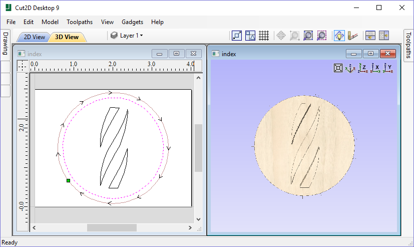
Overview of the Interface
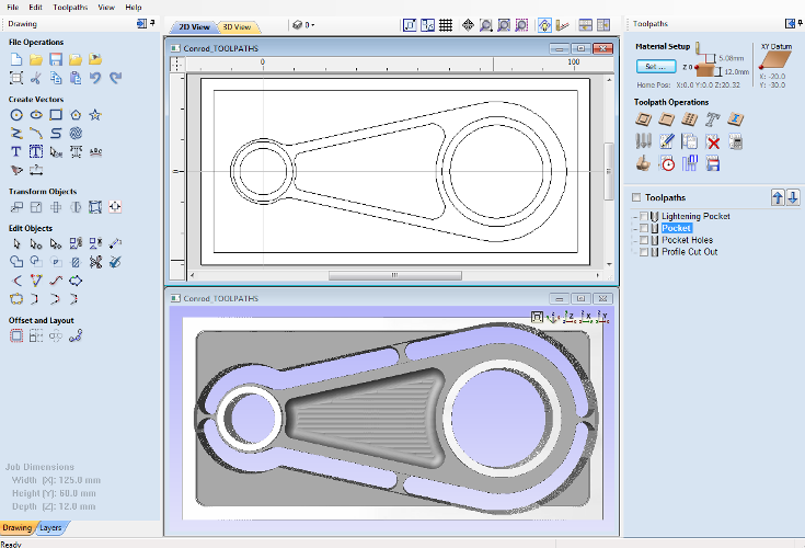
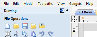
- The Main Menu Bar (the Drop Down Menus) along the top of the screen (File, Edit, Model, Toolpaths, View, Gadgets, Help) provides access to most of the commands available in the software, grouped by function. Click on any of the choices to show a Drop-Down list of the available commands.
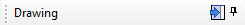
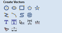
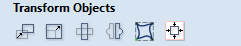
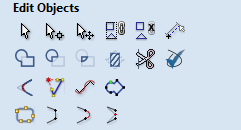
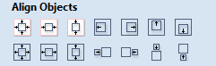
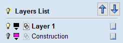
- The Design Panel is on the left side of the screen. This is where the Drawing and Layers tab can be accessed and the icons within the tabs to create a design.
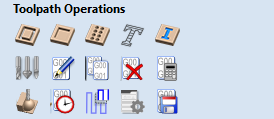
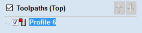
- The Toolpath Tab is on the right side of the screen. The Top section of the toolpaths tab houses all of the icons to create, edit and preview toolpaths. The bottom half shows you toolpaths that you have already created.
- The 2D Design window is where the design is drawn, edited and selected ready for machining. Designs can be imported or created directly in Cut2D Desktop. This occupies the same area as the 3D View and the display can be toggled between the two using F2 and F3 or the tabs at the top of the window.
- The 3D View is where the toolpaths and the toolpath preview are displayed.
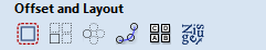
- If you wish to see the 2D and 3D views simultaneously, or you wish to switch your focus to the Toolpaths tab at a later stage of your design process, you can use the interface layout buttons (accessible in the 2D View Control section on the Drawing Tab) to toggle between the different preset interface layouts.
Managing the Interface
The Drawing, Layers and Toolpath tool pages have Auto-Hide / Show behavior which allows them to automatically close when not being used, thus maximizing your working screen area.
Cut2D Desktop includes two default layouts, one for designing and one for machining, which can automatically and conveniently set the appropriate auto-hide behavior for each of the tools pages. Toggle layout buttons on each of the tools pages allow you to switch the interface as your focus naturally shifts from the design stage to the toolpathing stage of your project.
Accessing Auto-hidden tabs
If a tools page is auto-hidden (because it is currently unpinned, see pinning and unpinning tools pages, below), then it will only appear as a tab at the side of your screen. Move your mouse over these tabs to show the page temporarily. Once you have selected a tool from the page, it will automatically hide itself again.
Pinning and unpinning tools pages
The auto-hide behavior of each tools page can be controlled using the push-pin icons at the top right of the title area of each page.
 |
 |
Pinned Open (auto-hide disabled) |
|
|
Un-pinned (auto-hide enabled) |

Default layout for Design and Toolpaths
Cut2D Desktop has two default tool page layouts that are designed to assist the usual workflow of design, followed by toolpath creation.