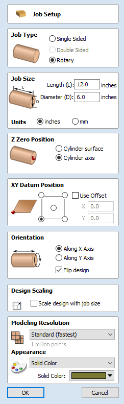
Job Setup - Rotary

The Job Setup form is displayed whenever a new job is being created, or when the size and position of an existing job is edited.
Job Type
Rotary job type enables the use of arotary axis (also called a 4th axis or indexer). Aspire will provide alternative visualisation, simulation and tools appropriate for rotary designs.
For more information about Single Sided job type see Job Setup - Single Sided.
For more information about Double Sided job type see Job Setup - Double Sided.
Job Size
Length
Length of the materialDiameter
Diameter of the material
Units
Whether the job units are measured in mm or inches
Z Zero Position
Indicates whether the tip of the tool is set off the rotation axis (as shown in the diagram) or off the surface of material for Z = 0.0. For the best accuracy using Cylinder Axis option is recommended
XY Datum Position
This datum can be set at any corner, or the middle of the job, when viewed as a flat 2d drawing. This represents the location, relative to your design, that will match the machine tool when it is positioned at X0, Y0. While this form is open, a red square is drawn in the 2d view to highlight the datum's position.
Use Offset
This option allows the datum position to be set to a value other than X0, Y0.
Orientation
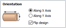
This option selects along which axis the material block will rotate.
- Selecting Along X Axis means that X coordinates represent movement along the cylinder, whereas Y coordinates represent the angle around the cylinder.
- Selecting Along Y Axis means that Y coordinates represent movement along the cylinder, whereas X coordinates represent the angle around the cylinder.
Flip Design
When this option is enabled, the design will be flipped when the orientation is changed
Design Scaling
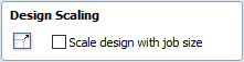
When editing the Job Size parameters of an existing job, this option determines whether any drawings you have already created will be scaled proportionally to match the new job dimensions. If you wish to preserve the existing size of your drawings, even after the job size has changed, leave this option unchecked. With this option checked, your drawings will be re-sized to remain in the same proportion and relative position within your new material extents when you click .
Modeling Resolution
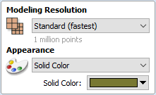
This sets the resolution/quality for the 3D model. When working with 3D models a lot of calculation and memory may be required for certain operations. Setting the Resolution allows you to choose the best balance of quality and speed for the part you are working on. The better the resolution quality chosen, the slower the computer will perform.
As this is completely dependent on the particular part you are working on and your computer hardware performance, it is difficult in a document like this to recommend what the setting should be. Generally speaking, the Standard (fastest) setting will be acceptable for the majority of parts that Aspire users make. If the part you are making is going to be relatively large (over 18 inches) but still has small details, you may want to choose a higher Resolution such as High (3 x slower) and for very large parts (over 48 inches) with small details then the Highest (7 x slower) setting may be appropriate.
The reason that the detail of your part needs to be taken into account is that if you were making a part with one large item in it (e.g. a fish) then the standard resolution would be OK but if it was a part with many detailed items in it (e.g. a school of fish) then the High or Highest setting would be better. As previously stated these are extremely general guidelines as on slower/older computers operations with the highest setting may take a long time to calculate.
As the Resolution is applied across your whole work area it is important to set the size of your part to just be big enough to contain the part you plan to carve. It would not be advisable to set your material to be the size of your machine - e.g. 96 x 48 if the part you plan to cut is only 12 x 12 as this would make the resolution in the 12 x 12 area very low.
Appearance
This sets the color or material effect which will be applied to the base 3D model. It is possible to change this at any time and also to apply different colors and materials to different Components using the Component manager.
In most cases a new job represents the size of the material the job will be machined into or at least an area of a larger piece of material which will contain the part which is going to be cut. Clicking OK creates a new empty job, which is drawn as a gray rectangle in the 2D View. Dotted horizontal and vertical Grey lines are drawn in the 2D design window to show where the X0 and Y0 point is positioned.