Model
| Create Component ► |
| Create Component From... ► |
 | |
 | |
 | |
| Export as Grayscale Bitmap |
| Export as 3D Clipart: Exports the selected model as a .3DClip file. |
 | |
 | |
 | Reset Inside Selected Vectors: Deletes everything in the Working Model contained inside the selected vector(s) |
 | Reset Outside Selected Vectors: Deletes everything in the Working Model contained outside the selected vector(s) |
 | Split Selected Component: Split the currently selected component using a vector. |
 | Create Vector Boundary Around Selected Components: Creates a new vector that matches the edge of the selected component. |
 | |
 | |
 | |
 | |
 |
 Create Component
 | |
 | |
 | |
 | |
 | |
 | Add Zero Plane: Creates a component that is the size of your job setup with a height of Zero. |
Create Component From...
 | |
 | |
 | |
 | |
 | |
| Create Component from Toolpath Preview |
Export As Grayscale Bitmap
This is export option will save the Composite Model (Working Model + visible Components) as a raster based image file (.bmp/.jpg/.gif format). This is mainly intended for users of Laser engraving equipment and CarveWright/CompuCarve machines. It could also be used to export the 3D as a grayscale for use with graphics programs.
When the image is exported the highest areas in the model will be white and the lowest will be black, all the other depths in between will be assigned graduated levels of gray depending on their relative position between the top and bottom of the part.


To use this function you must have either visible Components or something in the Working Model.
Create Component from Toolpath Preview
This will take the current Toolpath Preview and create a Component model from it. There are two main applications for this feature:
- It can be useful for helping to identify areas which have not been machined so a smaller tool can be used to carve them with more detail.
- It can be used to create model Components where some of the shape has been created using the tool shape such as fluted veins on a leaf or a texture toolpath]. This second application would be particularly beneficial for customers who plan to save a grayscale image of the 3D model (for Laser or CarveWright) rather than running the actual toolpaths from the software.
Once this is selected the current Toolpath Preview will be converted into a Component. This is then added to the Component List and will be called Toolpath Preview.
If the part has been cut-out and the Delete Waste Material option has been used then just the parts left on the screen will become the Component. If the part is not fully cut-out or the waste material has not been deleted then the whole Toolpath Preview block will become the Component, including what may be scrap material. It is possible to avoid this even without deleting the waste by using the Shift key - see below for more information.
By holding down either the Ctrl or Shift key, there are two options that can be activated when the Create Component from Toolpath Preview feature is selected.
If you press the Shift key when you create the Component, the areas of the Toolpath Preview over transparent areas in the composite model will be discarded. This will give you a Component that represents the Toolpath Preview but deletes anything that is not within the area of the 3D model the toolpaths were created on in the first place.
If you press the Ctrl key, the Component created will represent the difference between the composite model and the Toolpath Preview. The model this creates will look odd as it will just represent the material that was left by the radius of the tool on the finish cut. This can be useful if you want to machine those areas with a smaller tool as this model may then be used to create the vectors to limit the toolpath for that operation, minimizing the time to create a more detailed finish.
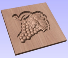
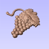
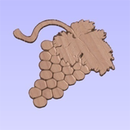
The images below show the 3 options available. Below left is the standard Component created from a machined model which includes the waste block. The middle option shows the option when the Shift key is pressed which discards the Preview model outside of the original area of the machined part. Finally the right hand image shows the Component which is created when holding the Ctrl key down which is the different between the original part and the Middle image.
IMPORTANT NOTE
Although this option can be selected at any time, it only makes sense to use this feature while the Toolpath Preview is active in the 3D View, this will ensure that the Component represents what can actually be seen. The Toolpath Preview can be accessed using the icon in the Toolpath Operations menu (shown below highlighted with a red box), this will also appear automatically after the calculation of any toolpath.