Quick Engraving Toolpath

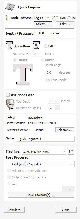
This form is used specifically for calculating engraving and marking toolpaths.
Watch this video to see this in action:
 Depth / Pressure
When using Conventional Engraving and End Mill cutters the Depth to engrave / mark is specified and this z depth dimension is output in the toolpath file sent to the CNC machine. The 3D Preview of these toolpaths shows the specified depth of engraving.
When using a Diamond Drag marking Tool the Pressure setting is used to pre-load the spring to ensure the tip of the diamond stays in contact with the material surface, especially when marking uneven surfaces. The 3D Preview of the depth these toolpaths will mark using the Angle of the diamond and the Width of the Line.
For example, when using a 90° Diamond Drag Tool with a 0.010 inch Line Width specified. The depth shown in the 3D preview will be 0.005 inch (with 90° the depth = half the line width).
The ratio of Depth to Line Width will change when using diamond drag tools with different tip angles. When the option to use a Nose Cone is selected (see below) the actual depth specified on the form is used when previewing the toolpath in the 3D view.
 Strategy
When using the Quick Engraving Form the Stepover for the cutter is specified on the form and is NOT automatically set from the Tool Database.
The selected text or vectors can be Outlined or Filled.
 Outline
The tip of the cutter runs on the selected lines engraving / marking the material surface

 Fill
Fill
A pattern is used to engrave / mark inside the selected text or vectors. There are 3 fill pattern options.


 Use Nose Cone
A nose cone is often used when engraving or marking material that is not flat. The nose cone is spring loaded forcing it to slide on the surface of the material. The engraving cutter is set to extend / protrude out of the bottom of the nose cone by the depth of engraving / marking required. This is typically set at around 0.010 inches to 0.020 inches.
When the option to use a Nose Cone is selected the actual depth specified on this region of form is used when previewing the toolpath in the 3D view.
 Number of Passes
This option runs the cutter multiple times divides over the toolpath pattern.
 Position and Selection Properties
 Safe Z
The height above the job at which it is safe to move the cutter at rapid / max feed rate. This dimension can be changed by opening the Material Setup form.
 Home Position
Position from and to that the tool will travel before and after machining. This dimension can be changed by opening the Material Setup form.
 Vector Selection
This area of the toolpath page allows you to automatically select vectors to machine using the vector's properties or position. It is also the method by which you can create Toolpath Templates to re-use your toolpath settings on similar projects in the future. For more information, see the sections Vector Selector and Advanced Toolpath Templates.
 Name
Name
The name of the toolpath can be entered or the default name can be used.
 Immediate Output
Once calculated, your toolpath is stored in the central Toolpath Tree and can be saved, edited or output to your machine at anytime using the command. In addition though, this form also includes a convenient Immediate Output section that allows you to save or send the most recently calculated toolpath directly from this form without having to close it.

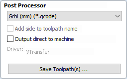
 Post Processor
Use this drop-down list to select the post-processor for your machine.
 Add side to toolpath name
If you are creating aligned toolpaths for a two-sided part, this option automatically adds the side name to the toolpath name as it is saved or exported to help keep your toolpaths organised.
 Output direct to machine
If your post-processor supports direct access to your cnc machine (including machines supported by VTransfer), this option will be available. Selecting this option will bypass saving the toolpath to disk and instead send it straight to the direct output driver.