Wrapped Job Setup
This gadget is used to simplify the task of setting up a job for machining 'flat' toolpaths wrapped on to a rotary axis / indexer. We highly recommend that you use this gadget to set up your job for rotary machining wherever possible as a number of other gadgets supplied by Vectric rely on information added to the job when this gadget is run.
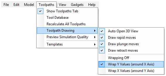
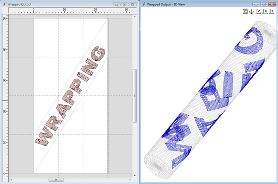
It is also important to note that all the wrapping gadgets work in conjunction with specially configured post-processors which take the XYZ 'flat' toolpaths and wrap them around a rotary axis, replacing either the X or Y moves with angular moves. The toolpaths can be visualized wrapped within the program using the toolpath menu as shown below...
To save the toolpaths in a format suitable for your machine control and rotary axis configuration you must have installed a suitable rotary post processor. Please see the Reference Manual section Rotary Machining and Wrapping for more information on the wrapping post processors.
The Wrapped job Setup gadget must be run before starting a new job. As soon as you start the program, before opening a new or existing file, select Gadgets ► Wrapped Job Setup from the main menu.
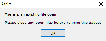
If you attempt to run the gadget with a file already open the following dialog will be displayed:
Running the gadget with no file open displays the form shown below.
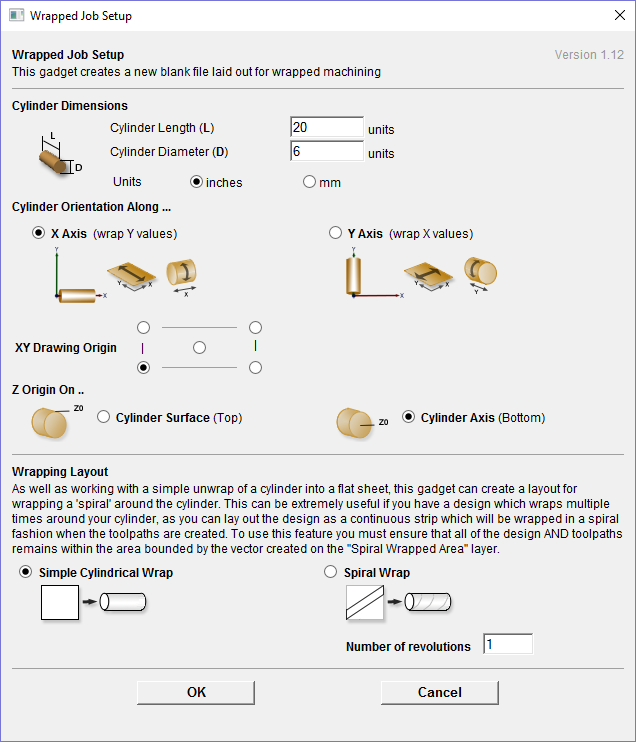
The form is divided into two main sections which we will discuss separately. The top part of the form allows you to enter details about the cylinder you will be machining on and your machine configuration. The bottom section of the form offers options on how the 2D view will be laid out.
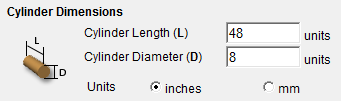
This section allows you to specify the size of the finished cylinder you will be working on. From these dimensions the gadget will calculate the circumference of the cylinder surface which along with the length of the cylinder will control the width and height of the 2D job. The diameter will also be used to set the thickness of the job in the program to the radius of your cylinder.
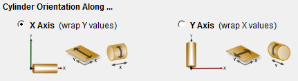
This section is used to tell the program how you have your rotary axis aligned on your machine. The images show the two supported options. If the centerline of your rotary axis is aligned along the X Axis of your machine pick the first option, otherwise the second. The gadget will remember your choices the next time it is run, so you should only have to make these choices once.
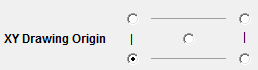
Here you can specify where the XY zero origin will be placed on your job. These options correspond to the same fields on the normal 'Job Setup' form within the program. Most people would use the default Bottom Left Corner, but for some jobs you may prefer to have the XY origin in the center.
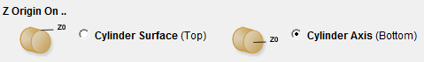
This section determines whether the Z Origin is set to the surface of the material or the base. These settings can be over-ridden when the toolpath is actually saved, but we would strongly recommend the 'Cylinder Axis' is selected for rotary machining. The reasons for this are detailed in the note below.
Note: Z Origin for Rotary Toolpaths.
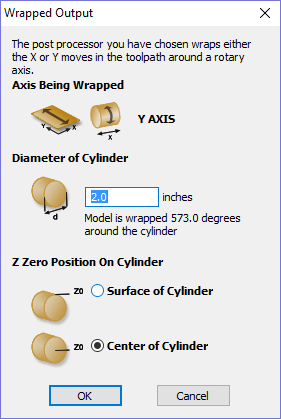
When you output a toolpath via a wrapping post-processor the following form will be displayed (this is for a post processor which wraps Y values around a cylinder aligned along the X axis) you have the choice of specifying if the tool is being zeroed on the center of the cylinder or the surface.
When you are rounding a blank, you cannot set the Z on the surface of the cylinder, as the surface it is referring to is the surface of the finished blank.
We would strongly recommend for consistency and accuracy that you always choose 'Center of Cylinder' when outputting wrapped toolpaths as this should always remain constant irrespective of irregularities in the diameter of the piece you are machining or errors in getting your blank centered in your chuck.
A useful tip for doing this is to accurately measure the distance between the center of your chuck and a convenient point such as the top of the chuck or part of your rotary axis mounting bracket.
Write down this z-offset somewhere, and zero future tools at this point and enter your z-offset to get the position of the rotary axis center.
The bottom section of the form offers two choices for how the job will be set out:
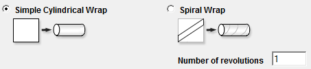
As well as working with a simple unwrap of a cylinder into a flat sheet; this gadget can create a layout for wrapping a 'spiral' around the cylinder. This can be extremely useful if you have a design which wraps multiple times around your cylinder, as you can lay out the design as a continuous strip which will be wrapped in a spiral fashion when the toolpaths are created. To use this feature you must ensure that all of the design AND toolpaths remains within the area bounded by the vector created on the Spiral Wrapped Area layer.
If you choose the Spiral Wrap option, enter the number of times you want your design to wrap around the cylinder. The screenshot below shows a simple 3 turn wrap in the 2D view and the wrapped toolpath.
Vector Layout
As well as creating a job at a suitable size for wrapping toolpaths, if this gadget is run from Aspire it will create a number of vectors which can be very useful when creating your wrapped job.
The vectors are created on their own individual layers and by default these layers are switched off to avoid cluttering up your work area. To switch on the layers, open the Layers control in the View Toolbar:
or go to the Layers Tab (Ctrl+L is the shortcut to show / hide it).
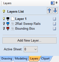
To show / hide the layer simply click on the check box next to the layer name.
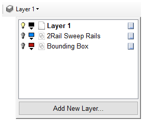
2 Rail Sweep Rails
This layer contains two straight line vectors which can be used to sweep a profile along if you are creating a shaped column.
Bounding Box
If you have chosen the 'Simple Cylindrical Wrap' option, this layer contains a rectangular vector covering the entire job area. This vector is useful if you are going to machine the complete surface of the cylinder.
Spiral Wrapped Area
If you selected the 'Spiral Wrap' option, this layer (which is visible by default) holds the vector bounding the area your design should be placed in to wrap correctly. This vector should also be used as a machining boundary if you are machining the complete surface of the cylinder.
In addition to the vectors created on layers, if you selected the 'Spiral Wrap' option, the gadget will create a series of horizontal and vertical guidelines to assist you in laying out your project.