Component Tree
Understanding the component tree and the composite model
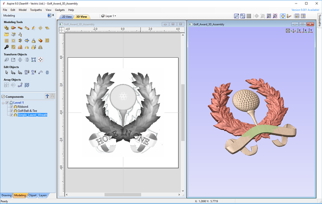
The model that you see in the 3D View is the result of progressively combining all of the visible components from the bottom of the Component Tree, to the top. The resulting model is known as the Composite Model. The order in which components are combined can have a significant impact on the final shape of the composite model and so you will often need to move components relative to one another within the Component Tree in order to achieve the end result you are intending.
To help you understand how the components are being combined, each component in the tree has an icon indicating how it is currently being combined with the components below:

Add

Subtract

Merge

Low

Group
Grouped components are also indicated by their own icon and the presence of a plus or minus control to the left of the visibility checkbox. These controls allow you expand or collapse the group to show or hide the group contents, respectively.
Every component exists on a single Level. These levels can be used to organize your modelling process. During the compositing process the contents of a level are combined first before the levels themselves are combined together.
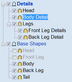
Currently Selected Level
Currently Selected Component
Components can be selected in 3 ways:
- By left-clicking on the component's name in the Component Tree
- By left-clicking on the associated grayscale component preview image in the 2D view
- By double left-clicking directly on the component in the 3D view
In all cases, the new selection will subsequently be reflected in all three locations. So, for example, selecting a component in the Component Tree will simultaneously cause the associated 2D component preview to become selected in the 2D View, and the same component to become highlighted in red (or green if the selected component is obscured by another component) in the 3D View.
There are, however, some minor differences between the three methods of selection. Also, depending on the circumstances, there may be some advantages to selecting your components using one method rather than another. These are detailed below.
Component Selection in the Component Tree
The component tree works in a similar way to the Window's file explorer. To select a component, simply click on it. To select multiple components, hold down a Ctrl key while clicking on each component you wish to add to the selection. While in this mode, clicking on a component that is already selected will cause it to be removed from the selection.
Pressing a Shift key allows you to select a range of components. Click on the first component in the range to select it, then holding a Shift key and pressing the last component you want selected will select all the components between the first and last selection.
Double-clicking a component or level in the Component Tree will automatically open the Component Properties tool - see the Component Properties section for more information on how to use this tool to modify the selected components.
Right-clicking an unselected component in the Component Tree will select it, and open its pop-up menu of related commands. Any commands you select will apply to this selected component only.
Right-clicking a component that is already selected, and is also one of several selected components, will open a similar pop-up menu of commands. Any commands you select from this menu will apply to all of the currently selected components.
Component Selection in the 2D View
The 2D component previews behave exactly the same way as vectors or bitmaps. They can be selected by a single, left-click. Several component previews can also be 'shift selected' (see above). Clicking on selected component previews again activates their interactive transform handles. These can be used to move, rotate or stretch the 2D component preview and its associated 3D component.
Component Selection in the 3D View
Because the left mouse button is used for twiddling the 3D view itself, a single left-click cannot be used for component selection directly. However, Aspire's 3D view supports most of the standard selection concepts described above, using double-clicks instead. Therefore, to select a component in the 3D view it must be double-clicked with the left mouse button. To select multiple components in the 3D view, hold down a Shift key and double-click each of the components you wish to add to the selection. To access the pop-up menu of commands associated with a component, double right-click it in the 3D View.
Because components may overlap or merge through one another when forming the composite model, you may find that some components become difficult (or are even impossible) to select directly from the 3D view using the double click method. In this case you may use the right click menu. If you right click on a point above the component you wish to select then you are presented with a list of all the components that lie under this point.
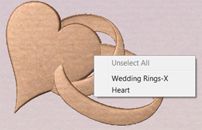
Right clicking on a point gives a list of all components under this point.
Choosing a component selects this component.
You can also double right-click the selected component (highlighted in red) in the 3D view. The options offered include showing/hiding components, or setting their combine mode within the composite model.
In the 3D view selected object will often be tinted red. On some occasions parts of some components will be obscured by other components. In this case then the red tint will not be seen. The parts of the objects that are obscured will be tinted green so they are still visible from within the 3D view.
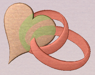
The parts of the selected component which are obscured are tinted a different color.
Component Editing in the 3D View
Many of the dynamic component editing tools can now be accessed directly from the 3D View. Editing the components in the 3D View makes it quick and easy to see the immediate effect of the changes to the Composite Model. To access these editing options a component or components must first be selected. Once selected then either clicking the component again in the 3D view or clicking the Transform Mode icon (Move, Scale, Rotate Selection) will activate the 3D Transform Handles. These take the form of solid and hollow blue squares around the component/s in the 3D View.
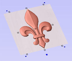
Clicking a selected component in the 3D View will activate the Transform Handles.
The majority of these will function in the same way that they do with objects in the 2D View. The hollow square in the middle of the component can be clicked and moved to reposition it. The hollow squares on each corner and in the middle of each side can be clicked and moved to re-size or scale the component (holding shift anchors this edit around the center of the object). The solid blue squares in each corner can be clicked and moved to rotate the object.
The additional larger solid blue square below the middle of the bottom edge of the model can be left-clicked to open a floating form that allows access to some of the components properties. This form can be moved if it is covering an important area of the job. From this form you can adjust the Combine Mode, Shape Height, Base Height, Fade and Tilt for the selected component/s. If you edit Fade or Tilt using this form, then when you click the Set button you must click the positions for this in the 3D View.
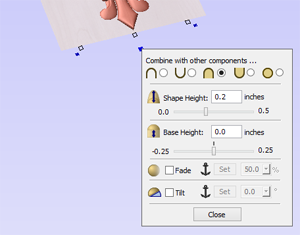
Clicking a blue square below the component opens a floating Component Property form.
Automatic Component Creation
Most of the modeling tools available under the component tree will act upon the current selected components. In most cases this means that you can simply select the component you wish to edit and click on the modeling tool you wish to use. If you select a modeling tool when no existing component is selected, Aspire will automatically create a new, blank component for you to begin working with. On closing the modeling tool, the newly created component will automatically be added to your model.
Component Management from within a modeling tool
Several of Aspire's modeling tool pages have a standard section to allow you to manage new components from within the modeling tool. This streamlines your workflow as it means you do not have to exit and re-enter a modeling tool when creating several components using the same modeling technique.
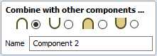
The component section of your modeling tool page allows you to edit the name of the component that will result from your modeling operation, and also the combine mode it will have when it is added to the component tree.
The process of adding the new component normally occurs automatically on closing the tool page. Alternatively, at any point when using the tool, you can press the Start New Component button. This will immediately create a component using the current results of your modeling operations and add it (with the name and combine mode indicated) to the component tree. In addition, it automatically creates a new blank component ready for you to continue the modeling process.
See 3D Design and Management for more information.