
Cut2D Laser Desktop User Manual

Version 9
Click on the region of the interface you are interested in:
|

|

|
Disclaimer
All CNC machines (routing, engraving, and milling) are potentially dangerous and because Vectric Ltd. has no control over how the software described in this manual might be used, Vectric Ltd. or any associated Resellers cannot accept responsibility for any loss or damage to the work piece, machine or any individual, howsoever caused by misusing the software. Extreme care should always be taken and the output from the software thoroughly checked before sending it to a CNC machine.
The information in this manual may be subject to change without any prior notice. The software described in this manual is supplied under the terms and conditions of the software license agreement and may only be used in accordance with the terms of this agreement.
Vectric Ltd.
Web: www.vectric.com
Email: info@vectric.com
Phone: +44 (0) 1527 850 323
Fax: +44 (0) 1527 850 323
Introduction
This manual is designed to provide a comprehensive description of all the functions, tools, menus and icons available within the Cut2D Laser Desktop software package.
Access this document from Cut2D Laser Desktop's Help Menu ► Help Contents or from the Cut2D Laser Desktop folder in the program section of your Windows Start menu.
At the bottom of the page you will see an area with View All Help. This will download all the Help Documentation as a single web page which is useful for searching or if you need to create a paper copy of the documentation.
User Guides, tutorial and training
Please note that this document is a Reference Manual. If you require more guidance, or are still learning how to use Cut2D Laser Desktop, please ensure that you view the Getting Started Video Tutorials in the Cut2D Laser Desktop Video Tutorial Browser when starting the software.
Cut2D Laser Desktop also includes an extensive selection of video tutorials, which are accessible from the Tutorial Video Browser link when application first starts. These tutorials cover every aspect of Cut2D Laser Desktop's functionality and range in complexity from a beginner's overview, to advanced features and principles. They are intended to be extremely accessible by level of experience or topic and use real-world examples throughout. Videos can be watched online, or installed locally.
We welcome any comments on this manual or the other training material, please email support@vectric.com with your feedback.
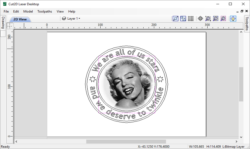
Overview of the Interface
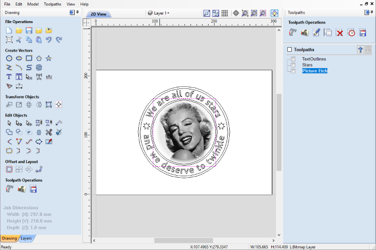
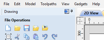
- The Main Menu Bar (the Drop Down Menus) along the top of the screen (File, Edit, Model, Toolpaths, View, Gadgets, Help) provides access to most of the commands available in the software, grouped by function. Click on any of the choices to show a Drop-Down list of the available commands.
- The Design Panel is on the left side of the screen. This is where the Drawing and Layers tab can be accessed and the icons within the tabs to create a design.
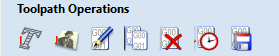
- The Toolpath Tab is on the right side of the screen. The Top section of the toolpaths tab houses all of the icons to create, edit and preview toolpaths. The bottom half shows you toolpaths that you have already created.
- The 2D Design window is where the design is drawn, edited and selected ready for machining. Designs can be imported or created directly in Cut2D Laser Desktop. This occupies the same area as the 3D View and the display can be toggled between the two using F2 and F3 or the tabs at the top of the window.
- The 3D View is where the toolpaths and the toolpath preview are displayed.
- If you wish to see the 2D and 3D views simultaneously, or you wish to switch your focus to the Toolpaths tab at a later stage of your design process, you can use the interface layout buttons (accessible in the 2D View Control section on the Drawing Tab) to toggle between the different preset interface layouts.
Managing the Interface
The Drawing, Layers and Toolpath tool pages have Auto-Hide / Show behavior which allows them to automatically close when not being used, thus maximizing your working screen area.
Cut2D Laser Desktop includes two default layouts, one for designing and one for machining, which can automatically and conveniently set the appropriate auto-hide behavior for each of the tools pages. Toggle layout buttons on each of the tools pages allow you to switch the interface as your focus naturally shifts from the design stage to the toolpathing stage of your project.
Accessing Auto-hidden tabs
If a tools page is auto-hidden (because it is currently unpinned, see pinning and unpinning tools pages, below), then it will only appear as a tab at the side of your screen. Move your mouse over these tabs to show the page temporarily. Once you have selected a tool from the page, it will automatically hide itself again.
Pinning and unpinning tools pages
The auto-hide behavior of each tools page can be controlled using the push-pin icons at the top right of the title area of each page.
 |
 |
Pinned Open (auto-hide disabled) |
|
|
Un-pinned (auto-hide enabled) |
Default layout for Design and Toolpaths
Cut2D Laser Desktop has two default tool page layouts that are designed to assist the usual workflow of design, followed by toolpath creation.
View Controls
Your project is represented using 2D and 3D workspaces, each viewed via independent windows called the 2D View and 3D View, respectively. This division usefully maps to the typical workflow in which you will initially focus on the 2D design and layout of your project before moving to the 3D stage of modeling, toolpathing and previewing your finished part.
You can switch between the views using the tabs at the top of each window. In addition the shortcut-keys F2 and F3 will toggle the display between the two windows.
It is sometimes useful to see both the 2D and 3D representations at the same time. The Page Up and Page Down keys will arrange the 2 views either horizontally or vertically so you can see both workspaces simultaneously. To return to the tabbed display, simply click on the standard Windows Maximize button in the top right corner of either view window.
Many of the controls for manipulating the view in your project are similar in both 2D and 3D.
From within each view you can also directly interact with the objects that make up your job using the Object Selection Tools.
2D View Controls
See also the Rulers, Guides and Snap Grid section.
 |
Pan |
Click and hold the Left mouse button and drag the mouse about to Pan - Esc to cancel mode Shortcut: Click and drag the Middle mouse button or if using a 2 button mouse, Hold Ctrl + drag with Right Mouse button. |
 |
Zoom Interactive |
Mouse with Middle Wheel - Scroll wheel in / out Mouse without Middle Wheel - Hold Shift + Push / Pull with Right Mouse button. |
 |
Zoom Box |
Click top left corner, hold mouse down and drag to bottom right corner and release. Clicking the left mouse button will zoom in, Shift + click will zoom out. |
 |
Zoom Extents |
Zooms to show material limits in the 2D window |
 |
Zoom Selected |
With objects selected Zooms to the bounding box of the selection |
How to Get Started
The first stage in any project is to create a new blank part or import some existing data to work with. At this stage a number of parameters need to be defined relating to the size of the part and its position relative to the datum location on the CNC machine. Later, once the part has been defined and you have started working, you may want to change the size of the material, import additional data and generally manage the project operation. In this section of the manual the initial creation of a part will be covered along with all the icons which appear under the File Operations section of the Drawing Tab.
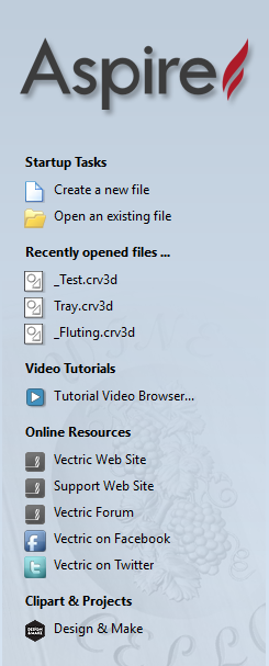
When you first start the program you will see the Startup Task options on the left hand tab and also a list of your 4 most recently opened Cut2D Laser Desktop parts (this is a rolling list that will be populated each time you run the software and may initially be empty).
Startup Tasks and Recently Opened Files
When you first start the program you will see the Startup Task options on the left hand tab and also a list of your most recently opened Cut2D Laser Desktop parts.
The first choice is whether you want to Create a new file or Open an existing one. Creating a new file allows you specify a size and location for a blank work area, set your material thickness and also set the model quality and even the shading color/material. The process to do this will be covered in the next section (Job Setup Form Options).
The second choice, Open an Existing File, will allow you to open a pre-created file from your computer. This may be a file you previously created in Aspire (*.crv3d), or a VCarve Pro job (*.crv). Alternatively, it might be a 2D vector layout from another CAD system (*.dxf, *.eps, *.ai and *.pdf). A CRV3D or CRV file will have the necessary information for material size etc. already embedded in it. The 2D formats will import the data at the size and position it was created but will require you to go through the Job Setup form to verify/edit all the parameters for the part.
Video Tutorials
The Tutorial Video Browser will open your default web browser (typically Internet Explorer, Chrome or Firefox - depending on your Windows setup and personal preference). The web browser offers a number of tutorial videos and associated files, presented either by project or feature category to help you to learn about the software. You will initially need internet access to watch or download the videos or files, but, once downloaded, the materials can be used offline.
Online Resources
This section includes direct links to useful websites and web resources - including clipart and projects for you to purchase, download and incorporate into your own designs. These links will also open in your default web browser and you will need internet access to use them.
Two-Sided Machining
Cut2D Laser Desktop has the ability to create a project where your design requires you to cut both sides of your material. Typically you will cut the top surface of your material, then manually turn the material block over on your machine, whilst maintaining a common registration position, and cut the bottom surface using a second set of toolpaths. By specifying a two-sided project using the Job Setup form and indicating how you intend to flip the material over on your machine, you can allow the registration and organisation of the geometry, toolpaths and previews relating to each side of the design to be managed by the software. During the design process you can then switch between the top and bottom surface of your design, create toolpaths for each side and view a preview of the material - including after it has been cut from both directions. Once you are happy with the result you can then save the toolpaths relating to each side independently.
Two-Sided Job Setup
In the Job Setup dialog, you can pick whether you want to create a single-sided or a double-sided job. You can change this setting later if you wish.
The initial Z-Zero Position you will be using for the toolpaths relating to each side is set from the Job Setup dialog. You can choose to Z-Zero from the same material surface for both sides, the machine bed for both sides or you can opt to Z-Zero from each side indepenendently. Your choice depends on the nature of your design. Typically, if you are only intending to carve into the surface on each side then you will Z-Zero each independently after you have physically positioned the material on your machine. If your design involves cutting through the material and the Z depths for each side must coincide precisely, however, then you will usually wish to use a common Z position for both sides. You can change the Z-Zero settings for each side subsequently using the Material Setup form.
The X Y Datum Position applies to both sides of the material.
In order to correctly manage the alignment of the geometry relating to each side, it is important that the software knows whether material will be flipped vertically or horizontally during the physical machining process. Flip Direction Between Sides determines the automatic transformation of the drawings, models or toolpaths associated with each side. If the material block will be flipped horizontally then the software will automatically mirror your data to mimick the relative positions each side.
When you create or open a two-sided project, Cut2D Laser Desktop will display two new icons in the 2D View Toolbar. The first icon indicates which flip direction option has been specified for this project. It will ininitially be set to display the Top Side of your design. Any drawing or toolpath creation will be associated with the Top Side and this is known as the active side. To work on the other side of your design you will first need to make the Bottom Side active. Click on the Toggle Side button in the View Toolbar to switch the active side between top and bottom. Alternatively, you can use the number key shortcuts: 1 will make Top Side active and pressing 2 will make the Bottom Side active.
Two-Sided Toolpath Management
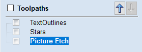
When toolpaths are created in a two-sided job they are automatically associated with the active side from which they were created. This helps you to keep track of which side of your job each toolpath is for. The toolpath list will only display the toolpaths for the current active side and this is indicated in the heading, which will read Toolpaths (Top) or Toolpaths (Bottom) accordingly. Changing the active side (using 1 or 2, for example) will cause the toolpaths list to also swap the displayed set of toolpaths.
Two-Sided Toolpath Previewing
The Preview Toolpaths form now includes a button. This will simulate toolpaths cutting both sides of your job (regardless of the currently active side) so that you can see the combined result of your toolpaths in a single, solid, 3D representation of the final job.
Two-Sided Toolpath Saving
Saving your toolpaths from a two-sided job is done independently for each side. Save the toolpaths for the currently active side, then make the other side active (using 1 or 2) and save out the toolpaths for the other side.
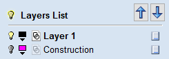
The View Toolbar

Above the view window is a handy toolbar that allows easier access to common tools. With the ability to create a double sided project you have easy access to switch between the Top and Bottom Sides of your project. The Layers Drop down bar has now moved from the drawing tab to the View Toolbar, making it accessible at all times. The other icons displayed in order of left to right are as follows:
Snapping Toggle Options
 Snap to geometry
 Smart Snapping
  Snap to Grid
 View Controls
 Toggle Pan / Twiddle View
 Zoom to box
 Zoom to drawing
 Zoom to selection
Toolpath Drawing Toggle
 Toggle 2D Toolpath Drawing
 Toggle solid 2D Toolpath Drawing
Two-Sided Machining

When you are working on a two-sided job additional icons will appear on the View Toolbar. On the left you will see an icon indicating whether the job you are working on will be flipped horizontally or vertically. This is important because the software will automatically mirror your toolpaths and geometry around different axes depending on this setting. To maintain the correct alignment of your toolpaths you must physically turn the material on your CNC machine in the same direction as you have specified during the design process.
 Turn horizontally from left to right.
 Turn vertically, end over end.
The next button indicates which side you are currently working on. It is a toggle button that can be clicked. Clicking this button swaps the active side of your job.
 Top side is active, all operations will apply to the Top side.
 Bottom side is active, all operations will apply to the Bottom side.
The final additional tool for two-sided job is on the right hand side of the View Toolbar and it allows you to toggle the 3D composite relief to show either the currently active side or your model only, or both sides of your model as a single solid block.
 Toggle Two-Sided View
2D Design and Management
The 2D View is used to design and manage the layout of your finished part. Different entities are used to allow the user to control items that are either strictly 2D or are 2D representations of objects in the 3D View. A list of these 2D View entities are described briefly below and more fully in later sections of this manual.
Ultimately the point of all these different types of objects is to allow you to create the toolpaths you need to cut the part you want on your CNC. This may mean that they help you to create the basis for the 3D model or that they are more directly related to the toolpath such as describing its boundary shape. The different applications and uses for these 2D items mean that organization of them is very important. For this reason Cut2D Laser Desktop has a Layer function for managing 2D data. The Layers are a way of associating different 2D entities together to allow the user to manage them more effectively. Layers will be described in detail later in the relevant section of this manual. If you are working with a 2 Sided project you can switch between the 'Top' and 'Bottom' sides in the same session, enabling you to create and edit data on each side, and using the 'Multi Sided View' option you can view the vectors on the opposite side. 2 Sided Setup will be described in detail later in the relevant section of this manual.
Vectors
Vectors are lines, arcs and curves which can be as simple as a straight line or can make up complex 2D designs. They have many uses in Cut2D Laser Desktop, such as describing a shape for a toolpath to follow or being a controlling 2D shape for use with one of the 3D modeling functions such as the 2 Rail Sweep. Cut2D Laser Desktop contains a number of vector creation and editing tools which are covered in this manual.
As well as creating vectors within the software many users will also import vectors from other design software such as Corel Draw or AutoCAD. Cut2D Laser Desktop supports the following vector formats for import: *.dxf, *.eps, *.ai, *.pdf, *skp and *svg. Once imported, the data can be edited and combined using the Vector Editing tools within the software.
Bitmaps
Although bitmap is a standard computer term for a pixel based image (such as a photo) in *.bmp, *.jpg, *.gif, *.tif, *.png and *.jpeg. These file types are images made up of tiny squares (pixels) which represent a scanned picture, digital photo or perhaps an image taken from the internet.
To make 3D models simple to create, Cut2D Laser Desktop uses a method which lets the user break the design down into manageable pieces called Components. In the 2D View a Component is shown as a Grayscale shape, this can be selected and edited to move its position, change its size etc. Working with the Grayscale's will be covered in detail later in this manual. As with bitmaps, many of the vector editing tools will also work on a selected Component Grayscale.
Vectors
Vectors have two very important uses:
- To describe the shape/boundary/direction of a toolpath
- To control 3D shapes created using the icons under the Modeling Tools
As they are such an important part of two of the fundamental areas of the software there are a lot of tools to create, edit and manage them. In this section all these tools and vectors options will be briefly described. For practical examples of these tools you should review the tutorial videos.
Vector Import
Decorative vector designs and shapes will often be imported from another drawing package such as Corel Draw, AutoCAD etc.
rather than being completely drawn in Cut2D Laser Desktop.
The Vector Import icon  is located in the File Operations area of the Drawing Tab.
Once a vector has been imported then the imported vector shape(s) can be modified, moved, scaled, rotated, mirrored or deleted the same as vectors created within the software.
is located in the File Operations area of the Drawing Tab.
Once a vector has been imported then the imported vector shape(s) can be modified, moved, scaled, rotated, mirrored or deleted the same as vectors created within the software.
The following Vector file formats can imported
SVG |
SVG files are two dimensional vector graphics which can be created within Vectric software but also from other CAD packages such as Inkscape or Adobe Illustrator. If you open this file type from File ► Open, this will automatically import the vectors and open up the Job Setup Form. If opened from the File ► Import ► Import Vectors, this will import the vectors directly into the current job. |
DXF and DWG |
Files from other CAD or graphics software packages such as AutoCAD will be opened in the original size and position. The Job Setup Form is automatically opened showing the maximum X and Y dimensions of the opened design. The actual size of the material can then be specified along with the required thickness and appropriate X0, Y0 and Z0 origins. |
EPS |
Files from typical design software such as Corel Draw can be opened. The Job Setup form will automatically be opened so the required material size can be specified. By default the EPS file will be placed with the lower left corner of the design at X0, Y0. |
AI |
Files from typical design software such as Adobe Illustrator and Corel Draw can be opened. The Job Setup form will automatically be opened so the required material size can be specified. The AI file will be placed with the lower left corner of the design at X0, Y0 |
|
Software such as the Adobe product range can be used to convert files from other design and word processing software into the industry standard PDF file format. The text and vector content of PDF files is extracted when imported into Cut2D Laser Desktop. When importing multiple page PDF documents each page is placed on a separate layer. |
While every endeavor is made to keep up with other software companies' changes in their file format it is possible that files in the above formats may not always be readable in Cut2D Laser Desktop. In that case going back to the original design systems and saving the file in an earlier version may enable it to be loaded into Cut2D Laser Desktop. In addition Cut2D Laser Desktop may not support the import of special entities such as dimensions, hatching, text, numbers etc. from some vector file types. It may be possible to adjust the formatting for these objects in their original design program. This is often done using a command called Convert to Curves. This will change this type of data to regular vectors that can then be exported in a compatible format for import.
Program Options
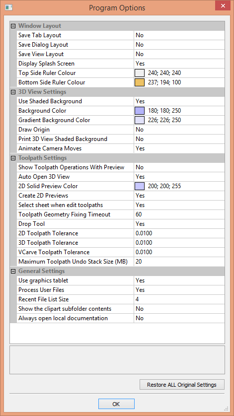 The options fall into four categories:
Window Layout
| Save Tab Layout | Save the layout and the 'pinned' state of the command and toolpath fly out tabs. |
| Save Dialog Layout | Save the size, position and visibility for dialogs such as the Layer control and Toolpath Control dialogs. |
| Save View Layout | Save the layout of the 2D and 3D view windows. |
| Display Splash Screen | Display the program Splash Screen, while the program is loading. |
| Top Side Ruler Color | The colour of the ruler on the top side in a two-sided project. |
| Bottom Side Ruler Color | The colour of the ruler on the bottom side in a two-sided project. |
Toolpath Settings
| Show Toolpath Operations with Preview | When the toolpath Preview form is visible, keep the 'Toolpath Operations' section visible (requires more screen space). |
| Auto Open 3D view | Automatically swap to 3D view after calculating a toolpath. |
| 2D Solid Preview Color | Color used to draw the solid 2D toolpath preview with. |
| Create 2D Previews | Create 2D previews of toolpaths in 2D view. |
| Select Sheet When Edit Toolpaths | If a toolpath is associated with a sheet, select sheet when edit toolpath |
| Toolpath Geometry Fixing Timeout | Number of seconds the program will spend trying to fix problems with geometry when calculating toolpaths. |
| Drop Tool | When projecting a toolpath onto the model, drop the tool on surface rather than project. If this is set, the toolpath will follow the surface of the model better, but could be slower to calculate. |
| 2D Toolpath Tolerance | Tolerance to apply to 2D toolpaths after calculating to reduce file size. |
| 3D Toolpath Tolerance | Tolerance to apply to 3D toolpaths after calculating to reduce file size. |
| VCarve Toolpath Tolerance |
Tolerance to apply to VCarve toolpaths after calculating to reduce file size.
Note: We strongly recommend that the Toolpath Tolerance should be
left at their default settings unless different values are recommended by your machine tool manufacturer.
If you do have a machine which struggles with the default settings, try doubling the values and cutting
a test-piece to assess the tradeoff between machining times, file size and final machined quality.
We have done some limited testing and on a sample complex 3D model, increasing the '3D Toolpath Tolerance'
to 0.001 inches gave a 40% decrease in file size and no noticeable difference in quality on the test machine
and job. In the test case there was no measurable difference in machining time on the CNC machine
the test was carried out on.
|
| Maximum Toolpath Undo Stack Size (MB) | Maximum size in MB of Toolpath data undo stack for storing toolpath delete state. |
General Settings
| Use Graphics tablet | Switch on support for graphics tablet drivers, if installed - for use with the sculpting tool. |
| Process User Files | Enable/disable processing of files in the 'Vectric Files' folder in your common user document folder. |
| Recent File List Size | This sets the maximum number of items that will be displayed in the Recently opened files... list in left hand side bar of the interface when there is no file currently loaded. The list will not increase in size until the software has been re-started and more files have been opened and/or saved. |
| Show the clipart Subfolder Contents | If set to Yes then this will show the contents within the selected Folder in the Clip Art browser along with up to 3 sub-folders if they exist and contain appropriate file types. If set to No it will only display the contents of the selected folder, not sub-folders. |
| Always open local documentation | Force open the local copy of the documentation when accessed through the Help menu. Cut2D Laser Desktop automatically opens the local documentation if you have no internet connection or if the server is taking too long to respond. |
Rulers, Guide Lines and Snapping
To help with drawing, construction and layout, the 2D View has Rulers which are displayed along the top and down the left side of the window. In addition to the Rulers there is the option to use Guidelines and The Smart Cursor to help with construction of vectors or positioning of other objects in the 2D View.
Rulers↓
The Rulers are permanently displayed in the 2D view to help with positioning, sizing and alignment. The graduated scale automatically uses the units set for the project and zooming in / out shows the sizes in 10ths.
←Guidelines
Guide Lines are used to help layout designs and make it very easy to sketch shapes by clicking on the intersections of Guides. Guide Lines are easily be added to the 2D view by pressing the left mouse button down on the appropriate ruler (left if you want a vertical guide and top if you want a horizontal guide) then holding the button down and dragging the mouse into the 2D view.
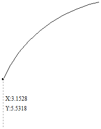
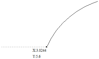
While dragging a Guide into position it automatically Snaps to the units displayed on the ruler. This snapping behavior can be overridden by holding down a Shift key while dragging the guide. After positioning a Guide it can easily be moved to a new position by clicking the right mouse button on the guide to open the Guide Properties form as shown later in this section. If you hover the mouse over a Guideline then its current position is displayed next to the cursor
Additional guide lines can be added relative to an existing guide line by interactively placing the cursor over an existing guide (the cursor changes to 2 horizontal arrows), Holding a Ctrl key and dragging to the required position. The incremental distance between the guide lines is displayed next to the cursor. Releasing a Ctrl key changes to display the absolute distance from the material origin.
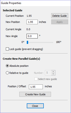
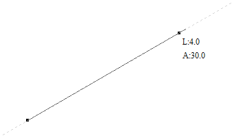
Guides can also be added and other edits made by right clicking on the Guideline which will bring up the Guide Properties form:
The exact position can be specified by entering a New Position.
Guides can be given an angle by either entering an angle into the New Angle box or dragging the slider and clicking . Angles are measured in degrees counterclockwise from the x-axis. From an angled guide you can only create relative parallel guides.
Guide lines can be locked in position to stop them from being inadvertently moved by ticking the Lock Guide option.
Additional Guide Lines can be added that are positioned using absolute or incremental coordinates. Enter the Absolute or relative positions and Click .
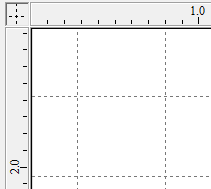
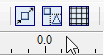
Guides can quickly be toggled visible / invisible by clicking in the Top Left Corner of the 2D view:
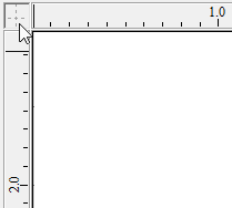
Alternatively the visibility can be changed using View Menu ► Guide Lines from the Main Menu. Guide Lines can be Deleted by selecting View Menu ► Guide Lines ► Delete All Guides from the Main Menu. Individual Guide Lines can be deleted by clicking and dragging them out of the 2D View Window.
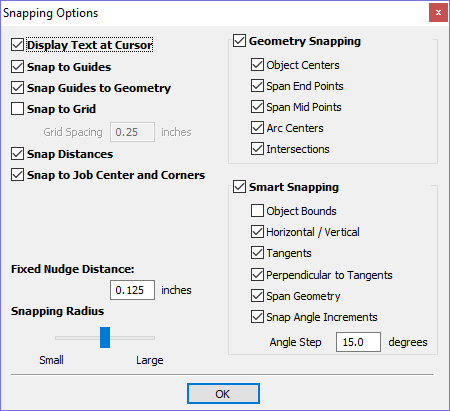
Snapping Options
These options can be used to help create and edit vector geometry.
The Snapping Options form can be accessed by selecting Edit ► Snap Options from the Main Menu or by pressing F4.
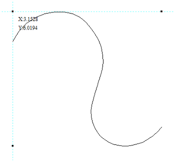
Display Text at Cursor
Displays the XY coordinates on the cursor making it easy to see the position for each point
Snap to Guides
When this option is checked ✓ drawing and positioning vectors will snap onto any horizontal or vertical guide lines visible in the 2D view.
Snap Guides to Geometry
When checked, ✓ the Guide Lines can snap to Geometry while being dragged.
Snap to Grid
Displays a grid of points separated by the Grid Spacing which can be snapped to when drawing or editing vectors and other objects in the 2D View.
Snap Distances
Snap to fixed lengths based on your zoom level. This occurs when creating shapes, dragging nodes or vectors.
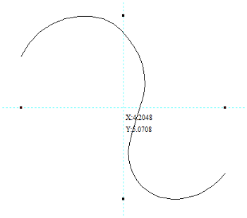
Snap to Job Center and Corners
Snap to the job corners and center. This, also, control the job smart snapping.
Fixed Nudge Distance
Objects can be moved small, fixed distances (nudged) by holding Ctrl+Shift and tapping the arrow keys. The Fixed Nudge Distance specifies the distance to move selected objects with each nudge.
Snapping Radius
The snap radius (pixels) will adjust how close the cursor must get to vector geometry in order to snap it. If you work quickly and grab and throw geometry at speed, you may prefer a larger Snapping Radius to pick up geometry that is vaguely near the mouse. If you work precisely or have complex overlapping geometry, you may prefer a smaller Snapping Radius to avoid having to zoom in to select one geometry in an area that has many nearby vectors.
Geometry Snapping
Used to control the position at which the cursor will snap when drawing and moving objects. When drawing, the cursor will snap to items on vector geometry depending what options you have selected in the form under this section.
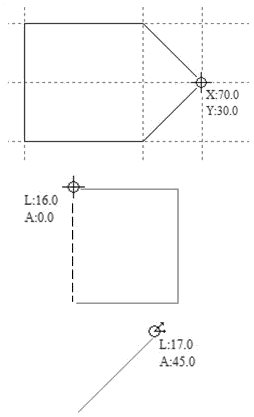
Object centers, Span End points, Span Mid-points, Arc centers, intersections Horizontally, Vertically and the specified Angle and Distance Guide lines and the intersection of Guides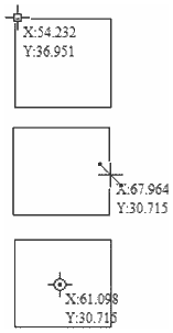
Snap to Nodes, mid-points, centers
Snap to Guides, matching horizontal and
vertical points, plus angle and distance
Smart Snapping
Smart snapping works by snapping the cursor to imaginary lines related to vectors and/or nodes. These lines will appear as dashed, and sometimes coloured, lines that go through the vector or node and the cursor point. You can snap to the intersection of those lines by hovering over the nodes that you're interested in. This reduces the need to create construction geometry (for example, for aligning nodes or vectors), and can be used in almost all the shape creation tools, node editing and transforming vectors.
Snapping lines can be drawn from:
- Nodes that were woken up by hovering the mouse over them or their span
- Vector properties, such as their bounding box or center point
- Material properties, such as extensions from the edge and the middle
| Cursor | Type | Color | Description |
|---|---|---|---|
 |
Object Bounds | The theoretical bounding box surrounding the active vector |
|


|
Horizontal and Vertical Lines |
Horizontal and vertical lines passing through a node or a span midpoint. |
|
 |
Tangents | Tangents originating from a node or a span midpoint. |
|
 |
Perpendicular to Tangents | Lines which are perpendicular to tangents from nodes or span midpoints. |
|
 |
Connecting Lines | Lines connecting two nodes. Includes mid-point |
|
 |
Span Geometry | (No line) | Snap to the geometry of the vector |
 |
Angular Constraints | Snapping to specific angles, as defined in the snap options F4 |
|


|
Job | Horizontal and vertical lines through the center of the job. |
Object Bounds
These snap lines appear on the bounding box edges of the vector, and in the middle horizontally and vertically.
Bounding Box
Object Centre
Vertical and Horizontal Lines
- Nodes
- The snap lines appear when the cursor is near the horizontal or vertical line passing through the woken nodes.
- Vectors
- Snap lines become available while moving vectors so that it is used for aligning them with other vectors.
Vertical
Horizontal
Tangents
These snap lines originate from the woken node and will appear as an extension along the end of the belonging span.
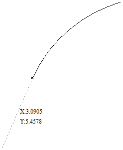
Tangent
Perpendicular to Tangents
These snap lines will be 90° from the tangent snap line, and they both
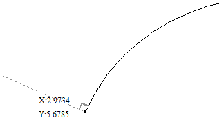
Perpendicular
Connecting Lines
If you wake two or more nodes, you could snap to the line connecting them. You could, also, snap to the mid-point of that line.
Connecting Lines
Span Geometry
This allows you to snap to the geometry of the vectors.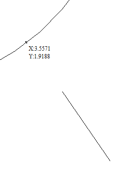
Span geometry
Angular Constraints
Angular Constraints eg. 30° (Angle step 15°)
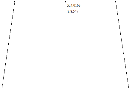
Job Edges & Centre
If you have the job snapping enabled, you could snap to the horizontal and vertical middle lines. This, also, includes the lines extending from the job's edges.
Job Center
Toolbar Snapping Options
Geometry Snapping, Smart Snapping and Grid Snapping can be switched on and off from the View Toolbar
Any change to the snap settings F4, through the Main Menu, or the toggles on View Toolbar will be remembered for subsequent sessions.
Snapping can be temporarily disabled by holding down the Shift key.
Document Variables
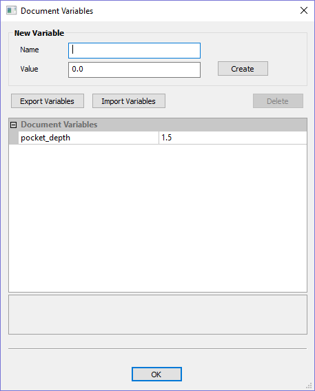
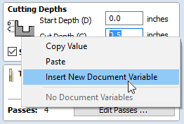
Document Variables provide a mechanism for defining values that can be used in Cut2D Laser Desktop's Document Variables. They can either be created in the Document Variables dialog (right) which is accessible under the Edit menu, or created from any Calculation Edit Box which supports variables by right clicking and selecting Insert New Document Variable from the Popup Menu.
Naming Document Variables
Right-click an edit-box to insert a new or existing Document Variable:
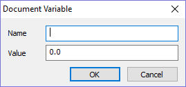
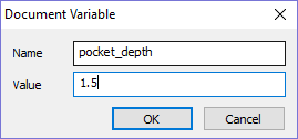
New Document Variable names must begin with a letter and then may consist of letter, number and underscore characters. Once created, they may be edited in the table beneath the New Variable section fo the Document Variables Dialog.
Variables can be exported to a text file and imported into another job. When importing, any existing variable values with the same name will be replaced.
Deleting Document Variables
Variables may be deleted if they're not being used in any toolpath calculations but only when there are no toolpath creation forms open.
Using Document Variables
Once created a Document Variable may be used in any Calculation Edit Box by enclosing its name within a pair of curly braces as illustrated in the figure below.
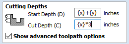
Right clicking in a Calculation Edit Box provides a Popup Menu that provides shortcuts for creating new Variables and inserting existing variables into the Edit Box.
Once a Document Variable has been created from the Popup Menu it will be inserted into the Edit Box.
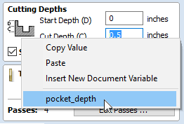
Accessing Document Variables
Declared Document Variables can be easily accessed from a calculation edit box. Right-click on the calculation edit box and you will be presented with a menu showing the document variables available currently, as well as an option to quickly insert a new document variable.
Calculation Edit Boxes
Numerical edit boxes generally support simple calculations.
A sum can be entered directly into the edit box:
Having typed an equation, pressing the = key will perform the entered calculation and fill the edit box with the answer.
Special Calculation Characters
As well as the simple numerical calculations, such as 3+(4/5), several of Cut2D Laser Desktop's stored values can be accessed by using certain letters (which are not case-sensitive): When used, Cut2D Laser Desktop substitutes the character with the appropriate value in the calculation.
Character |
Name |
Example |
Description |
|---|---|---|---|
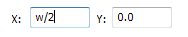
W or X |
Material Width |
w/2= |
Half of the material width |
H or Y |
Material Height |
H*2= |
Twice the height of the material |
T or Z |
Material Thickness |
t-0.25= |
0.25 units less than the material thickness |
P |
PI (3.141593) |
P*10^2= |
Area of a 10 radius circle (π.r2) |
I |
Imperial Conversion |
25.4*i= |
Converts 25.4mm to inches |
M |
Metric Conversion |
2*M= |
Converts 2 inches to millimetres |
' |
Feet |
2'+10= |
34 inches (2 feet and 10 inches) |
The Drawing Tab
Cut2D Laser Desktop includes drawing and editing tools that allow designs to be created and modified, which can ultimately be used directly for toolpath creation.
Commands for vector creation and editing are very easy to use and multiple design elements can also be drawn or imported, scaled, positioned and interactively edited to make a new design.
Text can also be created using any TrueType or OpenType fonts installed on your computer, or the single stroke engraving fonts supplied with the software.
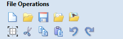
File Operations
Click on an icon to learn more about it:
| File Operations | |||||
 |
 |
 |
|
 |
|
 |
 |
 |
 |
 |
 |
New, Open and Save
|
Create a New File |
This option opens the Job Setup form (below), which is used to create a new blank job of the width (X), height (Y), and thickness (Z) required. The relative origins for X0, Y0 and Z0 are also specified at this point, and the measurement units can be set in either inches or metric. The Modeling Resolution and default 3D shading color/material can also be set at this stage. |
|
Open a File |
This option opens the File Open dialog window, allowing Cut2D Laser Desktop files (CRV) and importable 2D vector files to be selected and opened. |
|
Save a File |
This option opens the File Save As dialog window and allows the job to be saved as a Cut2D Laser Desktop file. Navigate to the required folder, enter a suitable name for the job and click the Save button. |
|
Import Vectors |
This opens the File Open dialog window and allows 2D DXF, EPS and AI and PDF files to be imported into the 2D View. The imported vectors will always be read in at the size and scale they were created in their original design software. Once open they can be scaled and edited in the same way as vectors created in Cut2D Laser Desktop. All the Vector tools will be dealt with in that section of this manual. To import toolpaths from PhotoVCarve and Cut3D (.PVC and .V3D file extensions), use File ► Import... ► Import PhotoVCarve or Cut3D Toolpaths from the main menu bar. Any Toolpath data saved as .PVC or .V3D files can be imported and will be visible in the Toolpath List. |
|
Import Bitmap |
This opens the File Open dialog window and allows image files to be selected and imported into the current open job. File types - BMP, JPG, TIF, GIF, PNG Images are imported to sketch vectors over the top of them, generate traced vectors. |
File Types
CRV |
Files previously created and saved in Cut2D Laser Desktop will be opened and displayed in the 2D Design window. All calculated toolpaths are stored/opened from the CRV file. |
DXF |
Files from other CAD or graphics software packages such as AutoCAD will be opened in the original size and position. The Job Setup Form is automatically opened showing the maximum X and Y dimensions of the opened design. The actual size of the material can then be specified along with the required thickness and appropriate X0, Y0 and Z0 origins. |
EPS |
Files from typical design software such as Corel Draw can be opened. The Job Setup form will automatically be opened so the required material size can be specified. By default the EPS file will be placed with the lower left corner of the design at X0, Y0. |
AI |
Files from typical design software such as Adobe Illustrator and Corel Draw can be opened. The Job Setup form will automatically be opened so the required material size can be specified. The AI file will be placed with the lower left corner of the design at X0, Y0 |
|
Software such as the Adobe product range can be used to convert files from other design and word processing software into the industry standard PDF file format. The text and vector content of PDF files is extracted when imported into Cut2D Laser Desktop. When importing multiple page PDF documents each page is placed on a separate layer. |
|
SKP |
SketchUp files with a .SKP extension (see www.sketchup.com) can be imported as 2D data suitable for machining. |
SketchUp Files
SketchUp files with a .SKP extension (see www.sketchup.com) can be imported as 2D data suitable for machining into a Cut2D Laser Desktop job using the File ► Import Vectors... command from the menu bar or the import vectors icon on the Drawing tab.
To import data from a SketchUp file you must already have created or opened a job to import the data into.
As a SketchUp model is usually a 3D representation of the part, the SketchUp importer offers a number of options to allow you to start manufacturing the model.
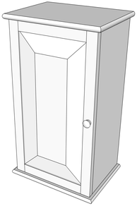
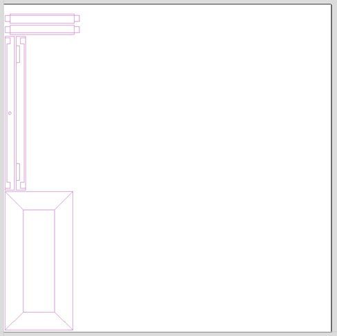
We will illustrate the two main choices for how the model will be imported using the SketchUp model shown to the left.
The model shown in the screenshots is a cabinet constructed by following the instructions in the Fine Woodworking 'Google SketchUp guide for Woodworkers: The Basics' DVD which is available via the Fine Woodworking site at www.finewoodworking.com. Vectric have no affiliation with Fine Woodworking, we are just using screenshots of the model constructed while following their tutorials to illustrate the process of importing a SketchUp model.
When the SketchUp model is selected from the File Import dialog, the following dialog will be displayed.
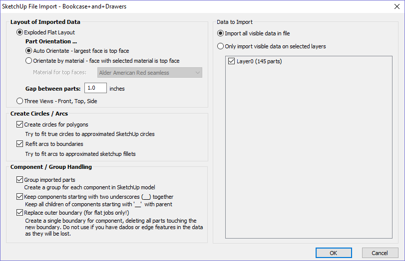
Although this initially looks complex, the dialog is divided into four logical sections which will be describe below.
Layout of Imported Data
In the first section there are two main choices for how the data from the model will be imported, 'Exploded Flat Layout' and 'Three Views - Front, Top, Side' as shown below.
We will describe the 'Three Views - Front, Top, Side' option first as it is the simplest.
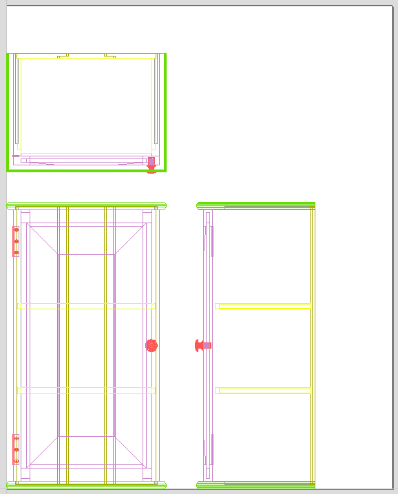
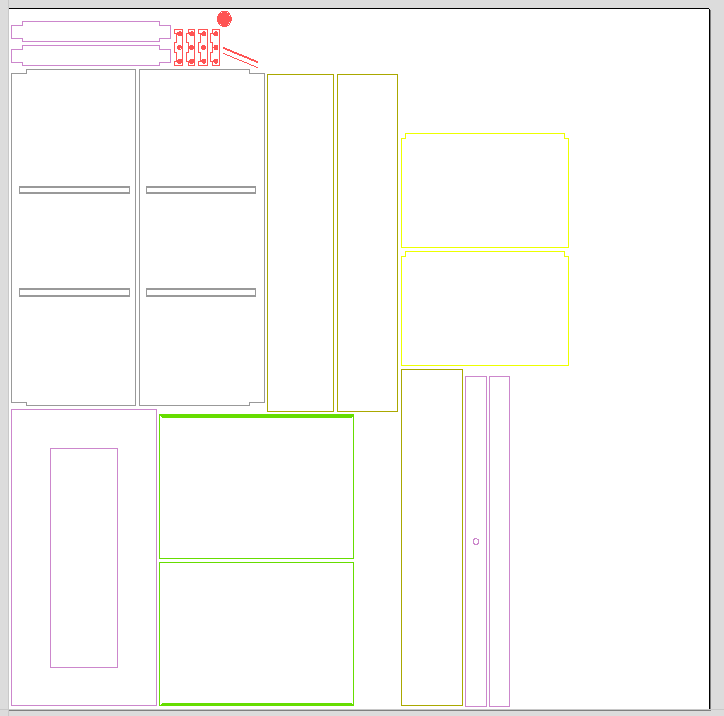
Three Views - Front, Top, Side
This option will create an 'engineering drawing' style layout of the SketchUp model as shown in the screenshot below.
The size of the model is preserved and it is relatively simple to pick up dimensions for parts you are going to manufacture from the various views. The colors of the lines you see are taken from the colors of the original SketchUp layers the various parts of the model are on.
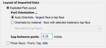
Exploded Flat Layout
This option will take each component in the model and orientate it flat ready for machining as shown in the screenshot below.
Once this option is selected a number of sub-options also become available.
Part Orientation
This section controls what Cut2D Laser Desktop considers to be the 'top' face of each part.
Auto Orientate
If this option is selected, for each part in the model, the 'face' with the largest area based on its outer perimeter (i.e. ignoring holes etc.) is considered to be the 'top' face and the part is automatically rotated so that this face is facing upwards in Z. This strategy works very well for models which are to be manufactured from sheet goods where there are no features on particular faces which need to be on the 'top' (such as pockets).
Orientate by material
This option allows the user to control more explicitly the orientation of each part in the model. Within SketchUp the user can 'paint' the face of each component/group with a material/color of their choice to indicate which face will be orientated on top when the model is imported. When this option is selected simply chose the material which has been used to indicate the top face from the drop down list. If a part is found in the model which does not have a face with the specified material, that part will be oriented by making the largest face the top.
Gap between parts
This field lets the user specify the gap between parts when they are first imported. After importing, the nesting functions within Cut2D Laser Desktop can be used to layout the parts with more control and across multiple sheets.
Create Circles / Arcs
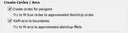
SketchUp does not maintain true arc or circle information for the boundaries of its parts. This is a problem when it comes to machining as the 'polygonal' SketchUp representation can give very poor machining results. For this reason, Cut2D Laser Desktop offers the option to refit circles and arcs to imported data.
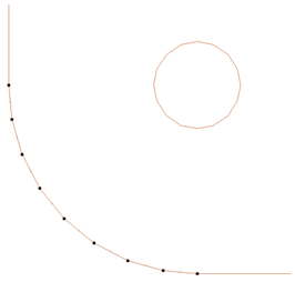
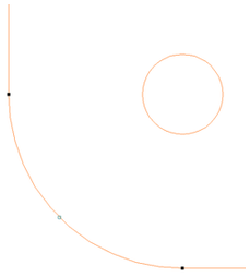
Options Checked ✓
Options Unchecked
The screenshot above left shows the results of importing a part with a filleted corner and hole with these options unchecked. The 'fillet' is made up of a series of straight line segments and the circular 'hole' is actually a polygon made up of straight lines.
The screen shot above right shows the same part imported with both these options checked ✓. The 'fillet' now consists of a single smooth arc and the circular 'hole' now also consists of arcs rather than straight line segments. Both these features will machine more cleanly in this form.
Data to Import
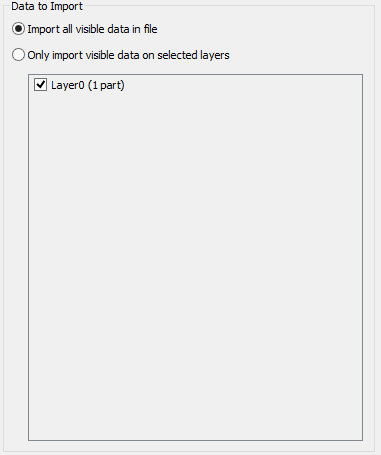
A SketchUp model will often contain parts that you do not wish to machine (such as hinges, knobs etc.) or data which will be cut from different thicknesses of material and hence different parts need to be imported into different Cut2D Laser Desktop jobs. To allow control over what is imported you can choose to only import parts of the model which are on particular layers using this section of the dialog.
To only import data from selected layers, choose the 'import visible data on selected layers' option and click the check box next to each layer to indicate if you want to import data from that layer. Note that the number of parts on each layer is displayed next to the layer name.
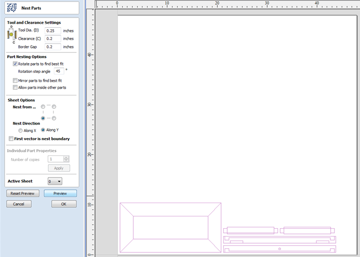
It is very easy to assign different parts of the model to different layers within SketchUp to help with the import process into Cut2D Laser Desktop. The screenshot below shows the result of only importing data on the 'Door' layer from the example.
As long as the 'Group imported parts' option is selected, these parts can then be easily nested ready for machining as shown in the image below (the 'Group imported parts' option is explained later in this section).
Component / Group Handling
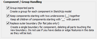
This section of the form allows advanced handling of how 'parts' within the SketchUp model are identified and treated on import.
Group imported parts
This option is normally selected for all but the simplest models as it allows each 'part' of the model to be selected, moved and nested easily after import. You will need to ungroup the imported data after nesting etc. to allow individual features to be machined. By default, Cut2D Laser Desktop will treat each SketchUp group / component as a single part UNLESS it contains other groups or components within it, in which case each lowest level group / component will be treated as a separate part.
Items which you retain in groups can be ungrouped at any time in the usual ways.
If the right-click menu-option to Ungroup back onto original object layers is used (which is the default option when using the icon or shortcut U) then the software will place the ungrouped items back onto the original layers they were created on in SketchUp.
Keep components starting with two underscores (__) together
If you have a complex model which contain 'parts' which are made up of other groups / components, you will need to do some work on your model to identify these parts for Cut2D Laser Desktop. The way this is done is by setting the name of the groups / components that you wish to be treated as a single part to start with__ (two underscore characters). For example, if you had a model of a car and you wanted the wheels / tires / hub nuts to be treated as a single part even though the Tire, Wheel and other parts were separate components, you would group the parts together and name them something like __WheelAssembly in SketchUp. When this model was imported, and Cut2D Laser Desktop reached the group/component with a name starting with __ it would treat all subsequent child objects of that object as being the same part.
Replace outer boundary (for flat jobs only!)
There is a style of 'building' with SketchUp where individual 'parts' are made up of several components 'butted' against each other. The screenshot below shows such a component.
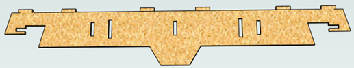
This object is made up of many smaller components representing the tabs on the top, the connectors at the end and the support at the bottom as shown below.
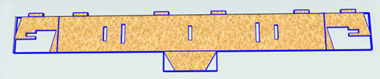
Although when can treat this as a single 'part' when imported by starting its name with __ (two underscores), the imported part is still going to be difficult to machine. The screenshot below shows the part imported into Cut2D Laser Desktop without the 'Replace outer boundary' option checked ✓. The part in the image has been ungrouped and the central vector selected.
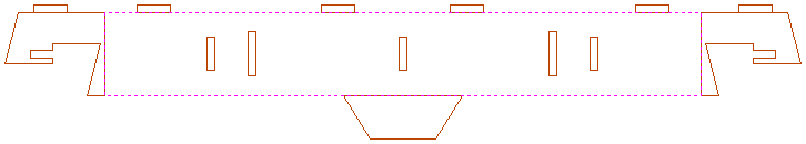
As you can see, the outer boundary is made up of separate segments for each 'feature'. Cut2D Laser Desktop does have the ability to create an outer boundary for vectors but this can be time consuming if it has to be done manually. If the 'Replace outer boundary' option is checked, ✓ for every part Cut2D Laser Desktop will try to create a single outer boundary and delete all the vectors which were part of this boundary. The screenshot below shows the result of importing the same data with this option checked, ✓ this time the part has been ungrouped and the outer vector selected.
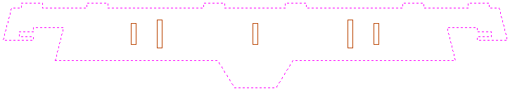
This data is now ready to be machined directly. It is important to understand the limitations of this option. It can be substantially slower. Creating robust boundaries for each part can consume a lot of processing power. Any feature which shares an edge with the boundary will be deleted. If the tabs on the top of this part were to have been machined 'thinner', this approach would not have been suitable as the bottom edge of the tabs has been removed.
The new features will help a lot of SketchUp users dramatically reduce the time it takes to go from a SketchUp design to a machinable part using Cut2D Laser Desktop.
It is important to understand though that while these options provide a useful set of tools, in many cases there will still be additional editing required to ensure the part is ready to toolpath.
Understanding the options and how they work will allow the part to be designed in SketchUp with these in mind and therefore help to minimize the time to machine once the data is imported.
Cut, Copy and Paste
The Cut, Copy and Paste functions in Cut2D Laser Desktop can be used on
|
Cut |
The Cut tool removes the selected objects from a design in a similar way to pressing the Delete key, but the selected objects are copied to the clipboard and can be Pasted into either the current file or a new file if required. Only one item can be Cut or Copied at a time. |
|
Copy |
The Copy tool copies selected objects to the clipboard, leaving the original in place and allows duplicates to be made and re-used in the design by pressing the Paste icon. Only one item can be Cut or Copied at a time. |
|
Paste |
This Paste option places the contents of the clipboard (created by Cut or Copy) into the design, allowing elements to be re-used in different areas of a design or in other Cut2D Laser Desktop parts. |
|
Undo |
Clicking this option steps backwards through the design changes made by the user. |
|
Redo |
Clicking this option steps forward through design steps that have been Undone using the Undo command (see above) to get back to stage that the user started using the Undo function. |
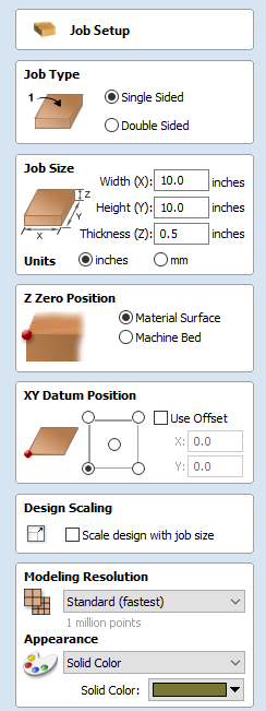
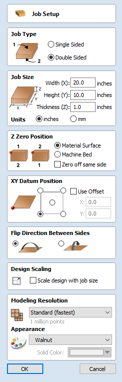
Job Setup
The Job Setup form is displayed whenever a new job is being created, or when the size and position of an existing job is edited.
Job Type
Select Single Sided if your design only requires the material to be cut from one side. This is the simplest type of job to design and machine.
If your design requires you to cut both sides of your material then Cut2D Laser Desktop also allows you to visualise and manage the creation and cutting process of both sides of your design within a single project file. Select Double Sided if you need this additional functionality.
Job Size
This section of the form defines the dimensions of the material block you will be using for your project in terms of width (along the X axis), height (along the Y axis) and thickness (along the Z axis).
It also allows you to select which units of measurement you prefer to design in - either inches (Imperial/English) or millimeters (Metric).
Height
The material length along the Y axis
Z Zero Position
Indicates whether the tip of the tool is set off the surface of the material (as shown in the diagram) or off the bed / table of the machine for Z = 0.0.
XY Datum Position
This datum can be set at any corner, or the middle of the job. This represents the location, relative to your design, that will match the machine tool when it is positioned at X0, Y0. While this form is open, a red square is drawn in the 2d view to highlight the datum's position.
Use Offset
This option allows the datum position to be set to a value other than X0, Y0.
Design Scaling
When editing the Job Size parameters of an existing job, this option determines whether any drawings you have already created will be scaled proportionally to match the new job dimensions. If you wish to preserve the existing size of your drawings, even after the job size has changed, leave this option unchecked. With this option checked, your drawings will be re-sized to remain in the same proportion and relative position within your new material extents when you click .
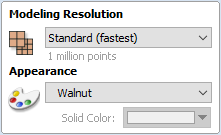
Modeling Resolution
This sets the resolution/quality for the 3D model. When working with 3D models a lot of calculation and memory may be required for certain operations. Setting the Resolution allows you to choose the best balance of quality and speed for the part you are working on. The better the resolution quality chosen, the slower the computer will perform.
As this is completely dependent on the particular part you are working on and your computer hardware performance, it is difficult in a document like this to recommend what the setting should be. Generally speaking, the Standard (fastest) setting will be acceptable for the majority of parts that Cut2D Laser Desktop users make. If the part you are making is going to be relatively large (over 18 inches) but still has small details, you may want to choose a higher Resolution such as High (3 x slower) and for very large parts (over 48 inches) with small details then the Highest (7 x slower) setting may be appropriate.
The reason that the detail of your part needs to be taken into account is that if you were making a part with one large item in it (e.g. a fish) then the standard resolution would be OK but if it was a part with many detailed items in it (e.g. a school of fish) then the High or Highest setting would be better. As previously stated these are extremely general guidelines as on slower/older computers operations with the highest setting may take a long time to calculate.
As the Resolution is applied across your whole work area it is important to set the size of your part to just be big enough to contain the part you plan to carve. It would not be advisable to set your material to be the size of your machine - e.g. 96 x 48 if the part you plan to cut is only 12 x 12 as this would make the resolution in the 12 x 12 area very low.
Appearance
This sets the color or material effect which will be applied to the base 3D model. It is possible to change this at any time and also to apply different colors and materials to different Components using the Component manager.
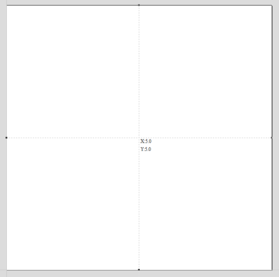
In most cases a new job represents the size of the material the job will be machined into or at least an area of a larger piece of material which will contain the part which is going to be cut. Clicking OK creates a new empty job, which is drawn as a gray rectangle in the 2D View. Dotted horizontal and vertical Grey lines are drawn in the 2D design window to show where the X0 and Y0 point is positioned.
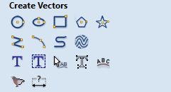
The Create Vectors Tool Group
Click on an icon to learn more about it:
| Create Vectors | |||||
 |
 |
 |
 |
 |
Closed Shapes |
 |
 |
 |
 |
Open Shapes | |
 |
 |
 |
 |
 |
Creating Text |
 |
 |
Trace Bitmap Dimensions | |||
Drawing Shapes
Each tool gives you the option of dynamically drawing with the mouse in the 2D View, or entering precise data using the form. When you click on a shape tool icon its associated form will open on the Drawing tab. Here you can see the precise dimensions of the shape you are working on, which you can edit directly, as well as other options specific to the type of shape you are editing.
If you click on a shape drawing tool when nothing is selected in the 2D View, you will be able to create new shapes using the button. If you select a previously created shape, you will be able to modify its properties using the same form and update the shape using the button.
Creating Text
There are a number of tools dedicated to the creation and editing of text. These can be found on the Drawing tab, below the shape creation tools.
Cut2D Laser Desktop can make use of any TrueType font already installed on your computer, as well as Vectric's own single-line fonts designed specifically for CNC machining.
Use the Draw Text, or Draw Auto Text, to create text within your design. The Text selection tool then allows you to dynamically alter the text positioning, spacing or even to bend your text into an arc. For even more flexibility, use the Text on Curve tool to place your text along any vector curve or line that you have drawn. The Convert Text to Curves tool allows you to then use Node Editing to fine tune the vectors of the text to any shape required.
The text tools are accessed using the following icons:
Trace Bitmap
Trace Bitmap tool allows you to automatically trace imported bitmaps using a variety of options within the tool to control the vectors that are created.
Dimensions
The dimensions tool allows you to add a variety of dimensioning annotations to your vector drawing.
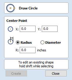
Draw Circle
Circles can be created interactively with the cursor and Quick Keys or by entering the exact coordinates and diameter / radius with typed input.
Interactive
Cursor
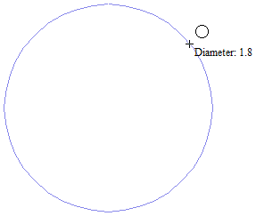
The default mode and the procedure for drawing circle is:
Click and drag the Left mouse to indicate the center point followed by releasing the button at the required radius / diameter (depends on what is set on the form).
As the cursor is dragged across the screen the radius is dynamically updated. The increments will depend upon your snap radius and the job size.
Quick Keys
The radius or diameter can be specified while dragging out a circle:
Type the value while dragging followed, by D if it's a diameter, or R if it's a radius:
| Keys | Result |
|---|---|
| 12R | Radius 12 |
| 2R | Radius 2 |
| 1D | Diameter 1 |
Exact Size
Circles can also be drawn by entering the required XY origin, selecting either Radius or Diameter and entering the required size on the form.
Click to update the circle.
Edit
Open the Draw Circle form and select the circle to modify.
The selected circle is displayed as a dotted magenta line. Edit the Center Point and Radius or Diameter
Click to update the circle
To modify another circle without closing the form hold a Shift key down and select the next circle.
Close the form
To finish drawing with the tool, you can:
- Click on the form
- Press the Esc key
- Click the Right mouse button in the 2D View.
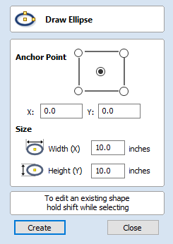
Draw Ellipse
Ellipse / ovals can be created interactively with the cursor and Quick Keys or by entering the exact coordinates for the center point, height and width with typed input.
Interactive - Cursor
The quickest and simplest way to draw an ellipse is:
- Click and drag the left mouse button in the 2D View to begin drawing the ellipse from its corner.
- While holding the left mouse button, drag to the required size.
- Releasing the left mouse button.
Holding Alt and dragging creates an ellipse from the middle point.
Holding Ctrl and dragging creates a circle.
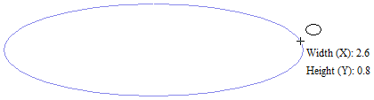
Quick Keys
Instead of releasing the left mouse button when you have dragged your shape to the required size, you can also type exact values during the dragging process and set properties precisely.
- Left-click and drag out your shape in the 2D View.
- With the left mouse button still pressed, enter a quick key sequence detailed below.
- Release the left mouse button.
Default
By default, two values separated by a comma, will be used to set width and height of your ellipse. One value will create a circle with the given diameter. While you are dragging out the ellipse, type Width Value,Height ValueEnter or Diameter,Enter to create an ellipse with the specified dimensions.
Example
| Keys | Result |
|---|---|
| 2.5,1Enter | Creates ellipse with a width of 2.5 and a height of 1. |
Specifying Further Properties
By using specific letter keys after your value, you can also indicate precisely which property it relates to.
| Quick Keys | Result |
|---|---|
| ValueX | Creates an ellipse at the current dragged height, but with the width set to the entered value. |
| ValueY | Creates an ellipse at the current dragged width, but with the height set to the entered value. |
| ValueWValueH | Creates an ellipse with a specified width (W) and height (H). |
Examples
| Keys | Result |
|---|---|
| 1X | Current dragged height with width (X) of 1. |
| 1Y | Current dragged width and height (Y) of 1. |
| 1W2H | A width (W) of 1 and height (H) of 2. |
Exact Size
Accurate ellipses can also be drawn by entering the required XY origin point with the Width and Height of the oval. Click to create the ellipse.
Edit
- Select the ellipse to modify and open the Draw Ellipse form.
- The selected shape is displayed as a dotted magenta line.
- Edit the Width and Height values.
- Click to update the ellipse.
To modify another ellipse without closing the form hold a Shift key down and select the next ellipse.
Close the form
To finish drawing with the tool, you can:
- Click on the form
- Press the Esc key
- Click with the Right-mouse button in the 2D View
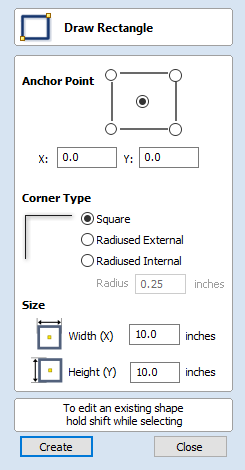
Draw Rectangle
Rectangles can be created by using the Draw Polyline tool or using the Draw Rectangle Tool. The latter tool allows rectangles to be created interactively with the cursor and Quick Keys or by entering the exact coordinates, type of corners (square, internal or external radius) and Width and Height using typed input.
Interactive - Cursor
The quickest and simplest way to draw a rectangle is:
- Click and drag the left mouse button in the 2D View to begin drawing the rectangle from its first corner.
- While holding the left mouse button, drag to the required size.
- Releasing the left mouse button.
Holding Alt and dragging creates a rectangle from the middle point.
Holding Ctrl and dragging creates a square.
As the cursor is dragged across the screen so the XY size is dynamically updated. The increments will depend upon your snap radius and the job size.
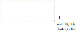
Quick Keys
Instead of releasing the left mouse button when you have dragged your shape to the required size, you can also type exact values during the dragging process and set properties precisely.
- Left-click and drag out your shape in the 2D View.
- With the left mouse button still pressed, enter a quick key sequence detailed below.
- Release the left mouse button.
Default
By default, two values separated by a comma, will be used to set width and height of your rectangle. One value will create a square with that side length. While you are dragging out the rectangle corner, type Width Value,Height ValueEnter or Side Length,Enter to create a rectangle with the specified width and height.
Example
| Keys | Result |
|---|---|
| 1,2.5Enter | Creates rectangle with a width of 1 and a height of 2.5. |
Specifying Further Properties
By using specific letter keys after your value, you can also indicate precisely which property it relates to.
| Quick Keys | Result |
|---|---|
| ValueX | Creates a rectangle at the current dragged height, but with the width set to the entered value. |
| ValueY | Creates a rectangle at the current dragged width, but with the height set to the entered value. |
| ValueRValueX | Creates a rectangle with a radius (R) and width (X) set by the two entered values, but using the currently dragged height. |
| ValueRValueY | Creates a rectangle with a radius (R) and height (Y) set by the two entered values, but using the currently dragged width. |
| ValueWValueH | Creates a rectangle with a specified width (W) and height (H). No radiused corners. |
| ValueRValueWValueH | Create a rectangle with radius (R), width (W) and height (H) all specified by the entered values. |
Examples
| Keys | Result |
|---|---|
| 1X | Current dragged height with width (X) of 1. |
| 1Y | Current dragged width and height (Y) of 1. |
| 0.1R1X | A corner radius (R) of 0.1, a width (X) of 1 and the current dragged height. |
| 0.1R1Y | A corner radius (R) of 0.1, a height (Y) of 1 and the current dragged width. |
| 1W2H | A width (W) of 1 and height (H) of 2, no corner radius. |
| 0.1R1W2H | A corner radius (R) of 0.1, width (W) of 1 and height (H) of 2 |
Exact Size
Rectangles can also be drawn by entering the required XY origin point with the Width and Height of the rectangle.
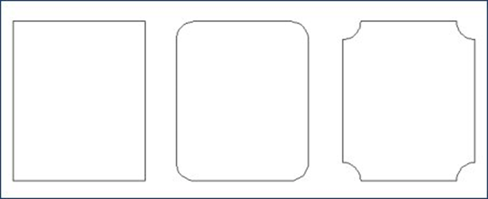
Corner Type
Corners of the rectangle can be Square, Radiused Externally or Radiused Internally.
Edit
- Select the rectangle to modify and open the Draw Rectangle form.
- The selected shape is displayed as a dotted magenta line.
- Edit the Width and Height values.
- Click to update the rectangle.
To modify another rectangle without closing the form hold a Shift key down and select the next rectangle.
Close the form
To finish drawing with the tool, you can:
- Click on the form
- Press the Esc key
- Click the Right mouse button in the 2D View.
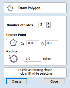
Draw Polygon
Polygons (e.g. Triangles, Pentagons, Hexagons etc.) can be created interactively with the cursor and Quick Keys or by entering the number of sides, exact coordinates and radius using typed input.
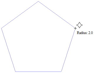
Interactive - Cursor
The quickest and easiest way to draw a polygon is by using the mouse in the 2D View.- Click and hold the left mouse button to indicate the center point.
- Drag the mouse while holding down the left mouse to required radius.
- Release the left mouse button to complete the shape.
As the cursor is dragged across the screen so the radius is dynamically updated. The increments will depend upon your snap radius and the job size.
Quick Keys
Instead of releasing the left mouse button when you have dragged your shape to the required size, you can also type exact values during the dragging process and set properties precisely.
- Left-click and drag out your shape in the 2D View.
- With the left mouse button still pressed, enter a quick key sequence detailed below.
- Release the left mouse button.
Default
By default, entering a single values will be used to set the radius of your polygon. While you are dragging out the polygon, type Radius ValueEnter to create a polygon with the precisely specified radius.
Example
| Keys | Result |
|---|---|
| 2.5Enter | Creates a polygon with a radius of 2.5, all other settings as per the form. |
Specifying Further Properties
By using specific letter keys after your value, you can also indicate precisely which property it relates to.
| Quick Keys | Result |
|---|---|
| ValueD | Creates a polygon with the diameter (D) specified, with all other properties as per the form. |
| ValueSValueR | Creates a polygon with the specified number of sides (S) and the outer radius (R). |
| ValueSValueD | Creates a polygon with the specified number of sides (S) and the outer diameter (D). |
Examples
| Keys | Result |
|---|---|
| 1R | Outer radius (R) 1, number of sides as per form. |
| 1D | Outer diameter (D) 1, number of sides as per form. |
| 8S1R | An 8 sided (S) polygon with an outer radius (R) of 1. |
| 6S2.5D | A 6 sided (S) polygon with an outer diameter (R) of 2.5. |
Exact Size
Polygons can also be drawn by entering the required XY origin , selecting either Radius or Diameter and entering the required size.
- Click to update the circle.
Edit
Open the Draw Polygon form and select the circle to modify.
The selected circle is displayed as a dotted magenta line.
- Edit the Number of Sides and Radius.
- Click to update the circle.
To modify another polygon without closing the form hold the Shift key down and select the next polygon.
Close the form
To finish drawing with the tool, you can:
- Click on the form
- Press the Esc key
- Click the Right mouse button in the 2D View.
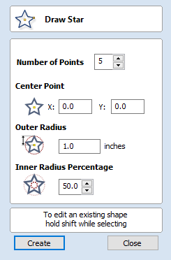
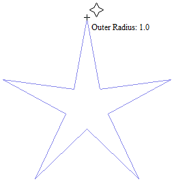
Draw Star
Stars can be created interactively with the cursor and Quick Keys, or by entering the number of points, exact coordinates and outer radius and inner radius percentage using typed input.
Interactive - cursor
The quickest and easiest way to create a star is by clicking and dragging the shape to size in the 2D View using the mouse.
- Click and hold the left mouse button to indicate the center point.
- Drag the mouse while holding down the left mouse to required radius.
- Release the left mouse button to complete the shape.
As the cursor is dragged across the screen so the outer radius is dynamically updated. The increments will depend upon your snap radius and the job size.
Quick Keys
Instead of releasing the left mouse button when you have dragged your shape to the required size, you can also type exact values during the dragging process and set properties precisely.
- Left-click and drag out your shape in the 2D View.
- With the left mouse button still pressed, enter a quick key sequence detailed below.
- Release the left mouse button.
Default
By default, entering a single value will be used to set the outer radius of your star. While you are dragging out the star, type Radius ValueEnter to create a star with the precisely specified outer radius.
Example
| Quick Keys | Result |
|---|---|
| 2.5Enter | Creates a star with an outer radius of 2.5, all other settings as per the form. |
Specifying Further Properties
By using specific letter keys after your value, you can also indicate precisely which property it relates to.
| Quick Keys | Result |
|---|---|
| ValueD | Creates a star with the outer diameter (D) specified, with all other properties as per the form. |
| ValueIValueR | Creates a start with the inner radius percentage (I) and the outer radius (R). The inner radius is defined in terms of a percentage of the outer radius or diameter. All other properties are as per the form. |
| ValuePValueR | Creates a star with the specified number of points (P) and the outer radius (R). |
| ValuePValueIValueR | Creates a star with the specified number of points (P), inner radius percentage (I) and the outer radius (R). |
Examples
| Quick Keys | Result |
|---|---|
| 1R | Outer radius (R) 1, other proporties as per form. |
| 1D | Outer diameter (D) 1, other properties as per form. |
| 6P1R | An 6 pointed (P) star with an outer radius (R) of 1. |
| 6P1D | An 6 pointed (P) star with an outer diameter (D) of 1. |
| 6P25I4D | A 6 pointer (P) star with an outer diameter (D) of 4 and an inner diameter that is 25% of the outer (i.e. 1). |
Exact Size
Stars can also be drawn by entering the Number of Points, Center Point, Outer Radius and Inner Radius Percentage.
- Click to update the star.
Edit
- Select the star to modify and open the Draw Star form.
The selected shape is displayed as a dotted magenta line.
- Edit the required parameters.
- Click to update the star.
To modify another star without closing the form hold a Shift key down and select the next star.
Close the form
To finish drawing with the tool, you can:
- Click on the form
- Press the Esc key
- Click the Right mouse button in the 2D View.
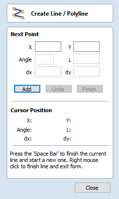
Draw Polyline
This tool creates continuous straight lines through points clicked, entered coordinates, tangent between a point and an arc or tangent to two arcs.
Interactive - cursor
The quickest and easiest way to draw a line is by clicking within the 2D View using the mouse.
- Click the left mouse button to indicate the start point of your line.
- Move the mouse pointer and click again to set the next point in your line.
- Repeat this process to add as many line segments as you require.
- Right-click or press Esc to finish your polyline and exit the form.
- Alternatively press the Spacebar to complete this polyline but keep the form open and begin drawing another polyline.
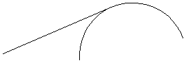
Creating Tangent Lines
The polyline tool can also be used create lines that are tangent to arcs in your existing drawing.
From A Point To An Arc
To create a line tangent from a point to an arc simply enter the initial point and then hover the cursor over the arc and press T.
From An Arc To A Point
To create a line tangent from an arc to a point click on the arc to insert a point and then hover the cursor over the next point position and press T.
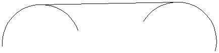
From An Arc To Another Arc
To create a line tangent from one arc to another click on the arc to insert a point and then hover the cursor over the second arc and press T.
Quick Keys
Instead of releasing the left mouse button when you have dragged your shape to the required size, you can also type exact values during the dragging process and set properties precisely.
- Left-click and drag out your shape in the 2D View.
- With the left mouse button still pressed, enter a quick key sequence detailed below.
- Release the left mouse button.
Default
By default, entering a single value will be used to add a point at the specified distance along the line direction currently indicated by the mouse pointer position, relative to the preceding point. With polyline drawing underway, move the mouse pointer in the direction you wish to create a new line segment and type Length ValueEnter to extend the line by the specified distance in that direction.
By default two values, separated by a comma, will create the next line point at the absolute X Y coordinate indicated by the two values, respectively. While drawing, type X Value,Y ValueEnter to place the next point precisely at specified X and Y position.
Example
| Keys | Result |
|---|---|
| 3.5Enter | Adds the next point at a distance of 3.5 along the line direction indicated by the current mouse pointer position. |
| 1,2.5Enter | Adds the next point at the absolute position 1 in X and 2.5 in Y |
Specifying Further Properties
By using specific letter keys after your values, you can also specify the line segment in terms of angle and length.
| Quick Keys | Result |
|---|---|
| ValueAValueL | Creates the next line segment at an angle (A) degrees from the last point and with a length (L). |
Examples
| Keys | Result |
|---|---|
| 45A3L | A line segment at 45 degrees (A) and a length (L) of 3. |
| 15A2.5L | A line segment at a 15 degree angle (A) and a length (L) of 2.5. |
Next Point
You can also use the form to enter values for each line segment as you go along. The segments can be defined using:
- The absolute X Y position of the next point
- The Angle and Length to the next point
- The relative offset in X (dx) and Y (dy) to the next point.
Once you have entered the values you wish to use:
- Click the button to enter a new point.
- The button deletes the last point entered and allows a new point to be added.
- The button completes drawing the current line and leaves the form open to allow additional lines to be drawn.
The Angle, Length and dx/dy positions are incremental from the current position.
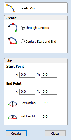
Create Arc
The Create Arc tool allows a single arc span to be created using precise values, or dynamically within the 2D View.
Through 3 Points
- Left click the mouse in the 2D View to set the start point of an arc.
- Click again to set the end point position.
- Move the mouse and click a third point to set the arc's radius.
Center, Start and End
- Left click the mouse in the 2D View to set the center point of the arc.
- Click again to set the start point of the arc.
- Move the mouse and click a third point to set the end point of the arc.
Exact Size
Precise values for the start and end point positions (in absolute X Y coordinates) and either the radius or the height of the arc can be entered in the form directly. Click to draw and arc using these values.
Editing An Existing Arc
The properties of an arc can be edited at any time by selecting the arc before choosing the Create Arc tool.
This opens the form with the current properties and position of the selected arc and these values can then be edited.
Click to update the selected arc with the new values.
Draw Curve
This tool creates a smooth, flowing, continuous curve through clicked points.
- Click in the 2D View to begin drawing at the clicked point.
- Move the mouse pointer within the 2D View and click the left button to insert as many points as you require. A curve will be created that smoothly joins your points.
- Click the right mouse button or press Esc to finish drawing your curve and close the tool.
- Alternatively, press Space Bar to finish drawing one curve, but keep the tool active so that you can immediately begin drawing another curve.
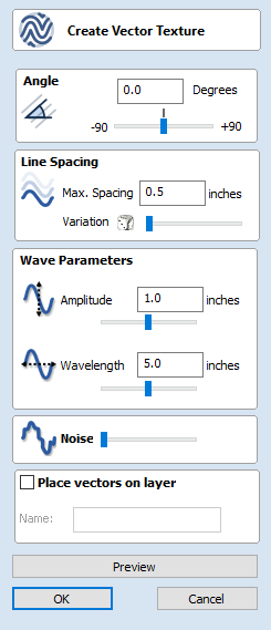
Create Vector Texture
Repeating texture patterns can be created using the Create Vector Texture tool. These vectors can be machined in a variety of ways to create attractive textures.
To use the tool click the icon on the drawing tab. If required, select any contours that you wish the pattern to be created within. By using the sliders and edit boxes on the form the style of the created pattern can be varied. Click to see a preview your created texture as you adjust the form's parameters. When you are happy with the preview, click to create the pattern.
Angle
The lines in the texture are created at an angle. This value can be set to any value between -90 degrees and 90 degree.

Angle of 30°
Line Spacing
The line spacing controls the distance between the contours created by the tool. Use the edit box labeled Max. Spacing to enter a maximum value of line spacing. The slider underneath the edit box controls the degree of variation in the line spacing. If the slider is to the far left then this mean variation is at a minimum and so the lines are evenly spaced. If the slider is to the far right the variation is highest and so the distance between created contours varies between zero and the maximum spacing specified.
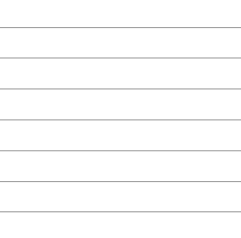
Minimum variation

Maximum Variation
Wave Parameters
Within this section of the form the created pattern can be made to behave in a wave-like fashion. This wave is controlled by two parameters: the amplitude and wavelength.
Wavelength
The wavelength describes the length over which the contours shape repeats itself. A bigger wavelength gives a long wave while a small wavelength gives a short wave.
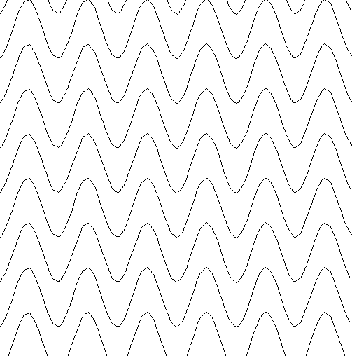
Short wavelength
Long wavelength
Amplitude
The amplitude describes the height of the wave. Larger amplitude means a taller wave and smaller amplitude means a shallow wave.
Small amplitude
Large Amplitude
Noise
The noise slider controls the degree of randomness applied to the above values and can be used to create less regular patterns.
No noise
Medium noise
High noise
Vector Layer
To create the vectors on a new layer make sure the check box labeled Place Vectors on Layer is checked ✓ and enter the layer name into the edit box labeled Name.
Applications
The vectors created by this function have many applications but a key one is to combine them with either a Profile Toolpath or where available the Texture Toolpath to create decorative panels and background textures, a small selection of the possible results you can derive from this combination are shown in the images below.
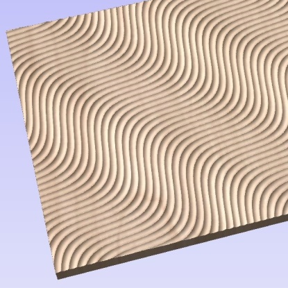
Ball Nose Tool - Wave Pattern

V-Bit Tool - Swirl Pattern
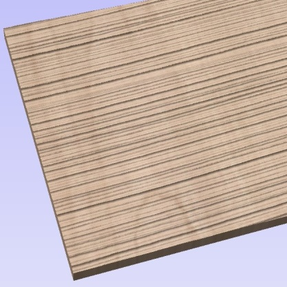
Ball Nose Tool - Grain Pattern
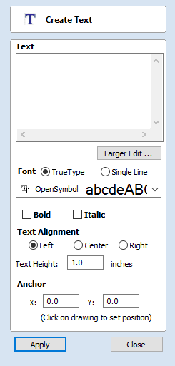
Create Text
This form allows text to be created at any height using the units the model is being designed in (Inch or MM).
Vertical Fonts
Fonts that start with the @ character are drawn vertically downwards and are always left justified.

Vertical Text
Engraving Fonts
The Single Line Radio Button changes the Fonts list to show a selection of fonts that are very quick to engrave.
Options
The button opens a larger text entry window that makes it easier to enter text that needs to run on longer line lengths. Clicking accepts any text entered into the window and will throw away any changes.
Text Alignment
Positions text relative to the full body of text, this only has a noticeable effect when writing multiple lines of text.
Anchor
Sets the position of your text block. Either enter values directly and click , or click in the 2D View with the mouse cursor to set the position values interactively. Clicking in the 2D View will begin a new block of text, set to the new Anchor point.
Edit Text
To edit text properties or content of previously created text:
If the Create Text form is open, hold the Shift key down and click the text you wish to edit or
If the Create Text form is closed, click the left mouse button on the text in the 2D View to select it before opening this form.
The form will now allow you to edit the properties of the selected text.
Click the button to update the changes in the 2D View. Click the button to finish or cancel the editing and close the form.
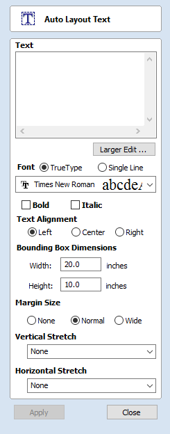
Draw Text Within A Box
This option automatically sizes a block of text to fit inside the boundary box (width and height limits) of a selected vector or vectors. If no vectors are selected the text is scaled to fit the size of the material.
When the Text form is open, the Dimensions for the Width and Height of the selected vectors or job dimensions are shown, and these are used to constrain the font size of the text.
Entering Text
The procedure for Drawing Text in the 2D Window is:
- Select the vector inside which the text is to be fitted
- Click the Draw Text icon
- Enter the required text content
- Select the font either True Type or Single Line as required and alignment options
- Click
Vertical Fonts
Fonts that start with the @ character are drawn vertically downwards and are always left justified.
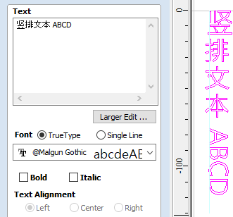
Vertical Text
Engraving Fonts
The Single Line Radio Button changes the Fonts list to show a selection of fonts that are very quick to engrave.
This example shows text (in an Engraving Font) drawn in an ellipse. The bounding box of the ellipse is used for the layout:
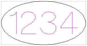
Options
The button opens a larger text entry window that makes it easier to enter text that needs to run on longer line lengths.
Clicking accepts any text entered into the window and will throw away any changes.
Text Alignment
Positions text relative to the selected bounding box or material size with options for left, center and right aligned.
Bounding Box Dimensions
These are the actual size of the box into which the text will be fitted. If the text is scaled interactively (by left clicking twice on the text) or precisely using the scale tool, the new bounding box is updated and displayed as a light gray rectangle.
Margin Size
The distance between the text and the bounding box where:
- None - Scales text to fit the rectangle width or height of the bounding box
- Normal - Scales text to fit within 80% of the bounding leaving a 10% border to the left and right.
- Wide - Reduces the size to 60% of the rectangle width leaving a 20% border to the left and right.
None
Normal
Wide
Vertical Stretch
When the text fits the width of the box and there is space above and below it, the text can be made to fill that vertical space using one these methods:
No Vertical Stretch
Stretch Line Space to fit
Stretch Characters to fit
Horizontal Stretch
When the text fits the height of the box and there is space at the sides, the text can be made to fill that horizontal space using one these methods:
No Horizontal Stretch
 Stretch Spaces between words
 Stretch Kerning (space between letters)
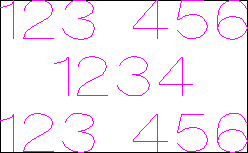 Stretch Character size
Edit Text
To edit text properties or content of previously created text:
If the Create Text form is open, hold the Shift key down and click the text you wish to edit or
If the Create Text form is closed, click the left mouse button on the text in the 2D View to select it before opening this form.
The form will now allow you to edit the properties of the selected text.
Click the button to update the changes in the 2D View. Click the button to finish or cancel the editing and close the form.
Text Selection
Interactive Letter kerning and Line Spacing
Select the cursor and click to select the Text to be edited. The text will be displayed as lines with 2 Green handles in the middle:

Letter Kerning
The interactive kerning and line spacing cursor is shown when placed between letters or lines:

The interactive letter kerning allows default text to be modified so that adjacent pairs of letters sit more naturally together. A typical example is shown above where the capital letters W A V are placed next to each other and the default space is excessive.
Place the cursor between 2 letters and click the Left mouse button to close the gap.
Holding a Shift key and clicking the Left mouse button moves the characters apart.
Holding a Ctrl key when kerning doubles the distance each letter moves on each click.
Holding Shift and Ctrl keys together and clicking the Left mouse button moves the letters closer together in larger increments.
Line Spacing
Line spacing can be modified by placing the Edit Text cursor between lines. It will change to the line spacing cursor:

Clicking Left mouse button will move the adjacent lines of text closer together.
Holding the Shift key and clicking the Left mouse button will move the lines apart.
Holding the Ctrl key doubles the distance each line moves on each mouse click.
Holding the Shift and Ctrl keys together and clicking the Left mouse button moves the lines apart in larger increments.
Text Arcing
The interactive rotation and movement cursor is displayed when the cursor is placed over either of the Green Handle to indicate that the text can be arced either Upwards or Downwards:

Bend Text Upwards

Bend Text Downwards
Click and Drag the Bottom Green box to arc the text Downwards.
Click and Drag the Top Green box to arc the text Upwards.
The text can easily be dragged back into the horizontal position using the green boxes.
After arcing text, additional Red and Blue handles are displayed for Rotating and Moving the text.
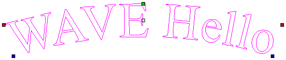
Clicking and dragging the Red boxes rotates the text around the center point of the arc.
Holding the Ctrl key forces the rotation to be in 15° increments. This allows the text to be positioned exactly on the horizontal or vertical quadrants, even after it may have been moved slightly.
Clicking and dragging the Blue boxes moves the text vertically and changes the radius onto which the text is mapped:
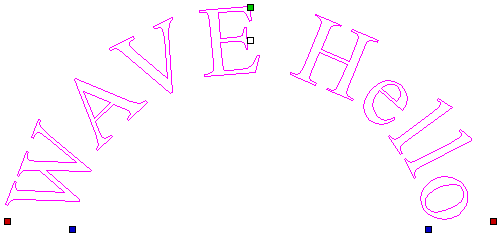
Convert text to Curves
In most cases all Text created in Cut2D Laser Desktop can be VCarved, Engraved, Pocketed and Profile machined or used with the 3D modeling functions. Some fonts do occasionally include loops and problems that need fixing using the Node Editing tools before it can be utilized for other functions. This text first has to be converted to Curves, creating lines, arcs and Bezier spans that can be interactively edited to fix the problem areas.
Script style fonts that are based on overlapping characters can be VCarved or Engraved without having to first convert the characters to curves.
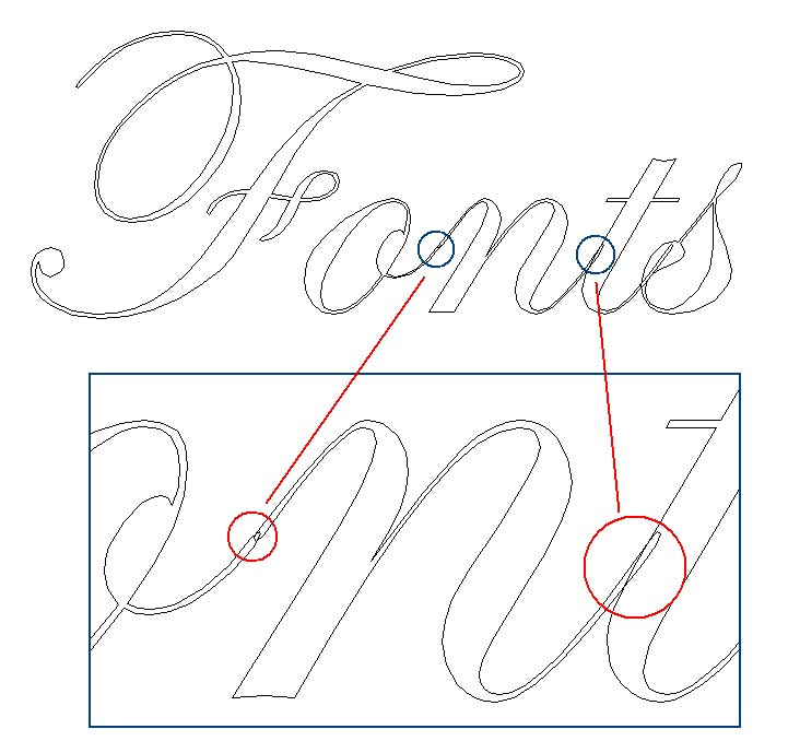
If the individual characters contain overlapping vectors or loops these will need fixing manually using the Node editing tools.
When Profile Machining with Tabs is required the text must first be converted to curves. Opening the Tab form on the Profile machining form will show a message stating that the text must first be converted to curves and clicking the button will automatically make the conversion.
Text can be converted to curves at any time by selecting the icon or clicking the Right mouse button and selecting Convert Text to Curves.
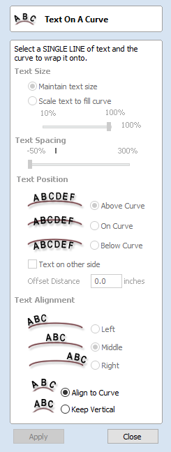
Text on Curve
This tool requires the user to select a single line of text with the Draw Text tool and a single vector curve/line. It will take the text and fit it onto the selected vector to follow the curvature. Options within the tool allow position, space and location against the line to be edited.
Text Size
Maintain text Size
Will not change the size of the text block

Scale text to fill curve
Will increase the character size in order to fit along the entire length of the selected curve.

Text Spacing
The slider can be used to increase or decrease the word and character spacing.
Text Position
The position of text relative to the curve is calculated using the height of the largest letter in the selected text string.
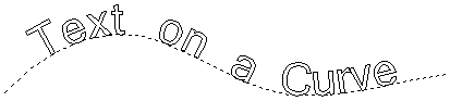
Above Curve
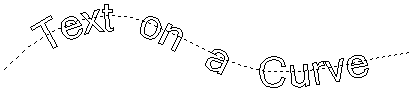
On Curve
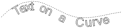
Below Curve
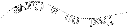
Text on other side
Offset Distance
Allows the text to be moved away from the curve by a specified distance.
Text Alignment
The 3 options allow the text fitted to the curve to be aligned to the left, middle or right hand side of the selected curve. Or, when using a closed vector curve, relative to the Start Node.
Characters in the text string can also be aligned 'normal' to the drive curve or left in the original vertical position.
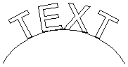
Align to Curve
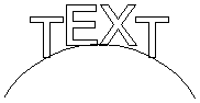
Keep Vertical
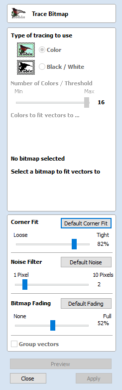
Trace Bitmap
This tool automatically traces or fits vectors to image files so they can be machined. Use the Import Bitmap tool and select the image in the 2D view, then open Fit Vectors to Bitmap.
After importing an image the Tracing option allows vector boundaries to be created automatically around colored or black and white regions in the image.
Tracing a Selected Area of the Bitmap
You can define an area within the bitmap, such that only that part of the bitmap will be traced. This can be done by selecting the bitmap (if this hasn't been done already), and then clicking and dragging the mouse over the area you want, to define a rectangular region on the bitmap. This will be highlighted with a dashed black rectangle.
Clicking on the Bitmap again will remove a selected area if one has been specified, in which case, the entire bitmap will have vectors fitted to it.
Images can be traced either in color or black and white mode and the basic process is described below:
If the image is black and white already, the process can be considerably simplified by selecting the Black/White option.
For color images you can also reduce the number of colors you need to work with by using the slider to further simplify the trace selection process.
Check ✓ the boxes next to each color swatch to link colors to the Trace Color. These are the colors that will be included in the area to trace.
Adjust the fitting parameters for the resulting vector and use the button to trace.
Click the button when you are happy with the preview.
After vector fitting you will often need to adjust the vectors so be sure to watch the video tutorials on vector editing available for the software.
Working with Color Images
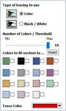
Color images are automatically reduced to 16 colors and the slider allows the visible number of colors to be set as required. Colors are merged with the closest match.
Colors can be temporarily linked together by clicking the check boxes next to each of the colors displayed. This changes the color displayed in the 2D view to the selected Trace Color. This is very useful for merging similar color's together to allow complete regions to be traced.
If a new Trace Color is selected the linked colors are displayed using this color in the 2D view.
The Reset button unlinks all the checked ✓ colors and the image displayed in the 2D view reverts back to the original 16 color image.
Working with Black and White Images
When working with Black and White images the slider can be used to change the Threshold and merge the levels of gray between all white (min), and all black (max).
When the image being displayed in the 2D view looks correct then clicking the button automatically creates vector boundaries either around the selected Trace Color or the grayscale.
Fitting-Options
The options available on this form control how closely the vectors fit / follow the selected color boundaries and these can be modified to obtain improved results.
Corner Fit
The Corner Fit control determines how accurately the vectors are fitted to the corner edges in an image.
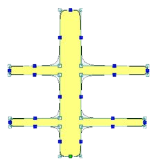
Loose
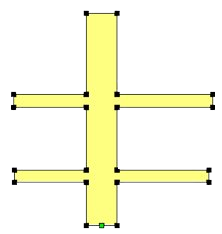
Tight
Loose
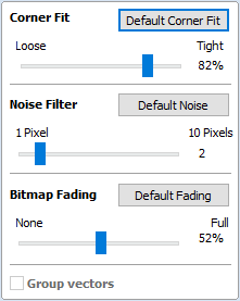
Loose will create smooth curves that may not follow corners very precisely, but will create smooth free-flowing vectorboundaries, with few nodes.
Tight
Tight inserts nodes to ensure the vector accurately follows the color boundary, to create sharp detail.
When using the Trace Color option it's sometimes useful to link a region of color's together, fit vectors and then link a new region or color's together, un-check the replace existing vectors option and fit another set of vector boundaries.
Noise Filter
The Noise Filter slider controls the minimum size of pixels that are traced / vectorized, preventing small unwanted vectors or noise being created.
For example, if an image contains single or very small clusters of pixels that aren't needed for machining a design. Then using the noise filter slider set at 4 pixels will ignore 2 x 2 or smaller pixel clusters.
Bitmap Fading
The Bitmap Fading slider controls the shading of the image in the 2D View. This is useful to see the trace vectors more clearly over high-contrast images.
Preview
This will preview the result of the tracing of the bitmap. If you are not happy with the result provided, you can alter the settings and click on the button again to get an updated result.
Apply
When you are happy with the result of the preview you can click on the button to keep it.
Close
Closes the Trace Bitmap form.
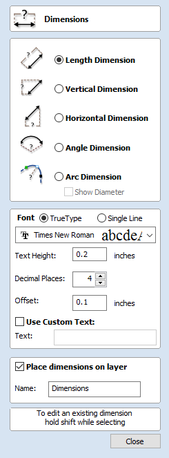
Dimensions
This tool allows you to add a variety of dimensioning annotations to your vector drawing.
Unless specified separately below, the dimensions are created using these steps:
- Select the dimension type you wish to need: length; height; width; angle or the radius or diameter of an arc.
-
In the 2D View, click with the left mouse button to set the points the dimension needs:
For an Angle Dimension, the first point is the centre-point. - Click where you need the arrow-tips to be.
- Click to set the location of the dimension-line.
- Click to set where the annotation text will appear.
- While dragging out a new dimension, a preview rectangle indicating the text size and position will be drawn.
- If you select a dimension before opening the Dimensions Form, the font properties can now be edited. Changing dimension-type or clicking a point on the screen while the form is open will start the creation of a new dimension.
- To edit an existing dimension while the form is open, hold down a Shift key while selecting it - there is a note on the form to remind you of this.
-
When creating Dimensions, the mouse snaps onto vectors, guide lines and the four corners / mid-points around the edge of the job setup area unless a Shift key is held down while dragging.
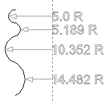
Arc Dimensions snapped to a guide line
Length Dimension
Use this to dimension a straight-line length in any orientation between two points.
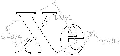
The text preview box will snap to to the middle of the dimension line, unless a Shift key is held down while dragging.
Vertical / Horizontal Dimension
These two options also allow any two points to be selected, but the resulting dimension will be locked to indicate a vertical or horizontal distance (respectively) between the two points.
The text preview box will snap to to the middle of the dimension line, unless a Shift key is held down while dragging.
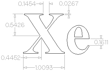
Angle Dimension
This option allows any arbitrary angle to be measured. The process is similar to creating a 3 point arc. First you must pick the center of an angle you wish to measure - typically a corner point. The next 2 points clicked will set the extents of the sweep you are measuring. The next Click will determine the dashed dimension line positioning and the final click will set the position of the text annotation.
- Angle Dimensions' arrow-heads will pop outside small angles if there is not room to draw them inside.
- Angles are extended with a dashed extension-line where required, allowing the dimension to be placed anywhere. The text snaps to the angle center and the leader-line angle snaps to horizontal, vertical or diagonal (disable snapping by holding down a Shift key).
- Angle Dimensions use a separate Decimal Places value to the other dimensions (as you change dimension-type you may notice the Decimal Places value change).
- Angle dimensions can now have up to six decimal places.
Arc Dimension
With this option selected you will only be able to select arc spans with the first click of dimension tool (Bezier curve spans are not supported). The second click will set the position of the dimension annotation, which will show the radius (or diameter) of the selected arc span.
- To display the diameter of an arc dimension simply check ✓ the Show Diameter box.
- Arc Dimensions recognise when a circle has been selected and allow placement anywhere around the circle. Arcs will now be extended with a dashed extension-line where required, allowing the dimension to be placed anywhere. The text snaps to the arc/circle center and the leader-line angle snaps to horizontal, vertical or diagonal (disable snapping by holding down a Shift key).
Circles or arcs that are polygonized (from an imported file or from the Curve fit vectors command using Straight lines) are not recognized and cannot be dimensioned with this tool (which is in line with snapping which also won't work on polylines to see if they are circular). Circular Polylines can sometimes be dimensioned using the length dimensioning tools across their diameter.
The  Fit Curves to Vectors command may be useful to turn polylines or bezier curves into arcs.
The text in the following example was first converted to vectors using the
Convert Text to Curves
command, then those vectors were converted to arcs using the
Fit Curves to Vectors
command:
Further Angle Dimension Examples:
Font Selection and Settings
This section of the form allows the user to change the settings for the dimension annotation, such as the font to be used, the height of the text and how many decimal places are required. The Offset field determines the gap left between the dimension markers and the vectors that are being measured.
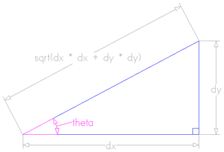
Use Custom Text
You can check ✓ Use Custom Text to insert your own custom text. The text is stored per dimension, so you change between calculated and custom text without losing a dimension's custom text. When the form is first opened it defaults to calculated text.
Place Dimensions on Layer
By default this option is checked ✓ and the dimensions will be placed on a mid-gray Dimensions Layer. You can edit the name of the layer in the Name edit field. If a layer of this name does not exist, it will be created automatically.
The base of extension lines and the tips of arrows are snap-points allowing you to keep neighbouring linear dimension lines, lined up, for example.
Transform Objects
Click on an icon to learn more about it:
| File Operations | |||||
 |
 |
 |
 |
 |
 |
The Transform Objects section contains all the icons which relate to commands for moving, sizing and manipulating objects.
Quick Keys
This reduces the time to create accurate geometry by allowing typed values while creating geometry. This is supported for creation of circles, ellipses, rectangles, polygons, stars, polylines and when in editing nodes or transforming vectors.
For example, while dragging to create a circle, typing 3R will create a circle with a radius of 3.
Inputting a Value
Input mechanism is as follows:
- Input the value first, and Enter to execute the default action (if applicable)
- Input the value first, and then a letter indicating the type of action required.
- Input 2 values separated by a comma, and Enter to execute a specified action (usually width and height or X and Y).
- Some actions require several input values.
- In that case, it will be valuelettervalueletter
- The action will be performed automatically once all letters required for that action have been entered.
You can enter a value and press Enter which will perform the default action.
The input times out after 5 seconds, if nothing was entered.
The value could be a simple expression, similar to that used from some of our text fields.
A full list of shortcuts can be found on the Shortcuts page
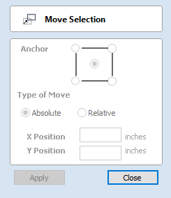
Move Selection
Selected items can be accurately moved and positioned using this option.
Anchor
The anchor position determines the point on your selected object's bounding box that will be moved to the absolute position entered.
Type of Move
Absolute
In this mode, the X Position and Y Position values will be used to position the object's anchor point directly.Relative
With this option selected, the values entered in the X Position and Y Position fields will incrementally offset the object from its current position, by the distances entered. The Anchor options are not relevant in this mode and so will be disabled.
The keyboard shortcut M opens the Move form in interactive mode.
Move Interactive
The default mode is to enable selected objects to be moved interactively by clicking and dragging with the cursor.
Holding down the Alt key when dragging objects around will constrain the movement to either the X or Y axes.
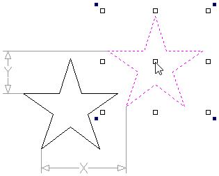
Pressing Esc or clicking will close the form.
A full list of Keyboard and Mouse shortcuts can be found on the Shortcuts page.
Quick Keys
For moving objects with a specific amount without having to go into the form, the Quick Keys can be used while dragging the object. Simply, activate interactive movement by clicking twice on the object, and then drag it and start typing the value as per the shortcut keys table. Then, either press Enter or the letter required to perform your action.
See Quick Keys shortcut table for a list of available actions.
Smart Snapping
To constrain the movement of the object in the X or Y axis, start dragging the object along that axis and a snap line will appear that represent that axis.
This can be used in combination with the Quick Keys, mentioned above, to move the object by a set amount in a specific direction.
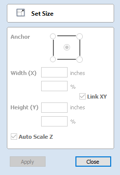
Set Size
Selected items in the 2D View can be accurately scaled or resized using this option.
Anchor
The anchor position determines the point on your selected object's bounding box that will be resized to the dimensions entered.
Link XY
Checking ✓ this option will always scale the height and width in proportion. Leaving the Link option unchecked allows non-proportional scaling
Auto Scale Z
This option sets a specific mode of scaling for 3D Components. When it's checked, ✓ scaling a model component in X or Y will result in it also scaling proportionately in Z, as such if you increase its size in X and/or Y then its Z Height will also increase and conversely when you reduce its X and/or Y size it will shrink in height. When it is unchecked then the Z Height of your Components will remain constant regardless of any X and/or Y scaling done either within this form or dynamically using the mouse in the 2D or 3D View.
Size Interactive
The default mode is to enable selected items to be scaled interactively by clicking twice with the mouse.
The process is:
- Select the vectors
- Click a second time to activate the interactive options - handles on the selection box
- Click and drag on the white handles
The keyboard shortcut T opens the Scale form in interactive mode.
Interactive Handles
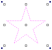
|
Handle |
Operation |
Additional options |
|---|---|---|
|
White Corner boxes |
Scaling proportionally |
Hold Shift for scale from middle |
|
White Center box |
Move the selected objects |
Hold Shift for linear X or Y moves |
|
White Middle Side boxes |
Scaling non-proportionally |
Hold Shift for symmetrical scale |
|
Blue Corner boxes |
Rotating dynamically |
Hold Shift 15° increments |
Quick Keys
For scaling objects with a specific amount without having to go into the form, the Quick Keys can be used while dragging one of the scaling handles around the object.
Dragging an edge handle, a single value is expected to determine the amount of change in that direction. This can be a relative value or an absolute value.
Draggina a corner handle, two values are expected with the new width and height of the object. Alternatively, a single value followed by S to scale relatively.
See Quick Keys shortcut table for a list of available actions.
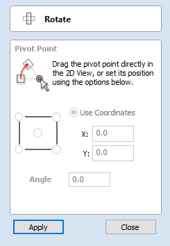
Rotate
For precise control of the rotation, or to use a point other than the selection's center as the rotation center, you can open the rotation form from the Drawing Tab.
Selected items in the 2D View can be rotated to a new orientation using this tool. The rotation options form can be activated from the tool icon on the Drawing Tab. Alternatively you can use the interactive transform mode (where the form is not required) directly from the 2D View.
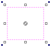
With this form open the additional Pivot Point handle is available (two concentric circles initially positioned at the center of your selection) for you to click and drag in the 2D View. The Pivot Point (around which the selection will be rotated) responds to the currently enabled snapping options to help you to position it precisely on significant locations within your artwork. Hold down the Shift key to temporarily disable snapping while you drag the Pivot Point.
Pivot Point
On the form there are also six radio button options for snapping the rotation Pivot Point to the selection itself or to a precise position. The first five options allow you to snap to the corners and center of your selection.Use Coordinates
This sixth option allows you to precisely specify the position of the Pivot Point using the X and Y edit boxes. This is also the option that will be selected by default if you drag the pivot point using your mouse directly in the 2D View.
Angle
The Angle edit box allows you to specify a precise rotation angle to apply to your selection. Click the button to rotate your selection by the value in this box.
A positive angle results in a counterclockwise rotation
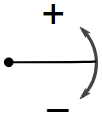
A negative angle results in a clockwise rotation
Rotate Interactive
Generally the most convenient way to rotate an object in the 2D View is to use interactive transform. This mode is initiated by clicking the selected object twice with the cursor. The process is:
- Select the object by clicking on it in the 2D View (or multiply select objects using box selection or by shift-clicking on them).
- Click the selection a second time to activate the interactive options rotation handles on the selection box.
- Click and drag on the blue handles (solid squares) at the far corners of the selection to rotate it.
Quick Keys
For rotating objects with a specific amount without having to go into the form, the Quick Keys can be used while dragging one of the rotation handles around the object.
See Quick Keys shortcut table for a list of available actions.
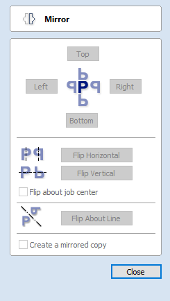
Mirror
Selected vectors/bitmaps/component grayscale previews can be mirrored to a new orientation.
Selected objects can also be mirrored about axes of symmetry relative to the bounding box of the selection, using the standard options on the Mirror Form.
- Select the object or objects to mirror.
- Click on the Mirror icon to open the Mirror Form.
- Select the Create a mirrored copy option to leave the selection and create a new set of objects.
- Click the button to accept the changes.
Shortcuts
The Shortcut Keys page describes these and other shortcuts that are used in Cut2D Laser Desktop.
| Shortcut key | Description |
|---|---|
| H | Mirror Horizontally |
| Ctrl + H | Create Mirror Copy Horizontally |
| Shift + H | Mirror Horizontally, around center of material |
| Ctrl + Shift + H | Create Mirror Copy Horizontally, around center of material |
| V | Mirror Vertically |
| Ctrl + V | Create Mirror Copy Vertically |
| Shift + V | Mirror Vertically, around center of material |
| Ctrl + Shift + V | Create Mirror Copy Vertically, around center of material |
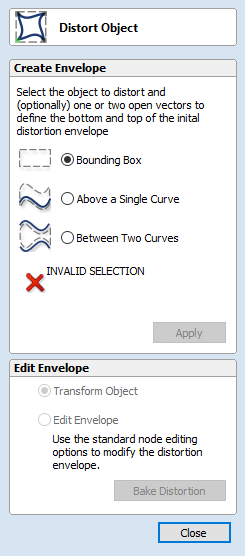
Distort Tool
This tool allows you to bend and flex a vector by manipulating a distortion envelope using Cut2D Laser Desktop's standard node editing tools. You can select one or more vectors and then use one of the three different tool modes to create your initial distortion envelope.
Once the distortion envelope has been created, you can use Cut2D Laser Desktop's node editing tools to add or edit its nodes and spans. As you alter the shape of the envelope the associated object will be distorted to reflect the changes.
Baking Distortion into an Object
Once an object has been distorted, node editing will always relate to the object's distortion envelope. If you wish to edit a distorted vector directly again, you will first need to permanently apply the distortion to the shape.
If you select an object that already has a distortion envelope while in the Distort Object tool, the button will be available. Clicking this button will permanently apply your current distortion and you will then be able to either distort the object again (with new settings), or node edit the shape directly.
Bounding Box
This option is available if you have a selection of vectors . It creates a distortion envelope based on the closest bounding box that can be drawn around your selection. Thus the resulting envelope is always initially a rectangle, comprising four line spans and a node at each corner. Using the normal node editing tools, however, you can modify this envelope as much as you like and the shape within it will be distorted accordingly.
Along a Single Curve
This option is only available if the last item in your selection is an open vector that Cut2D Laser Desktop can use to define a curve, above which the other selected objects will be distorted. The distorted object can comprise one or more vectors .
Using this option, you will usually end up with your objects bent to match the curve in your original selection. The distortion curve itself is left unchanged by this operation.
Between Two Curves
This option will become available if the last two objects in the current selection are open vectors, between which the other objects can be distorted.
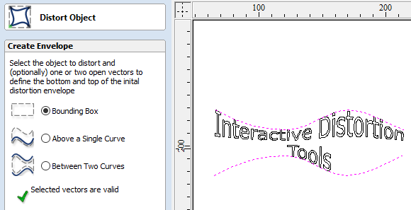
The other objects in the selection can comprise one or more vectors .
Therefore two examples of valid selections for this operation would be:
- 3 vector shapes and 2 open curves
but not:
- 1 vector shape, 1 component and 2 open curves.
The selected objects will be stretched and squeezed between the two curves that were last in the selection. Neither of the contributing distortion curves in the selection will be altered by the operation.
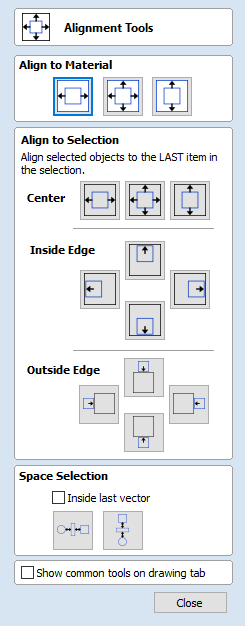
Alignment Tools

The Align Objects tool provides a number of options for accurately aligning the selected object to other objects in the selection, or to the available material.
| Align Objects | ||||||
|
 |
 |
 |
 |
 |
 |
 |
 |
 |
 |
 |
 |
 |
The different alignment options are grouped into three sections:
- The first section of icons all work in relation to the material (job size).
- The second section of icons all work with regard to the selected items.
- The last section provides options to evenly space the selected objects, or to align them inside the boundary of the last object in the selection.
Align to Material
The options in this section will align one or more selected objects within the material workspace defined when you setup your job (the white area in your 2D View).
Center in Material

This option moves the selected items to be positioned in the middle of the material. The short-cut key for this is F9.
Center in Material X only

Align items centrally in the material only moving them along the X axis so the vertical position will not be changed.
Center in Material Y only

Align items centrally in the material only moving them along the Y axis so the horizontal position will not be changed.
Align to Selection
The different items comprising your design in the 2D View can be aligned relative to one another using the following selection sequence:
- Select the item/s you wish to align / move (use single or multiple selection options).
- Hold the Shift key down.
- Select the final item - this is the object that the rest of the selected items will be aligned to Click the required alignment option.
There are 7 alignment options for aligning the selection to the inside edge:
Align Center

Center selected items in the middle (both horizontally and vertically) of the last selected item.
Align horizontal center

Align the selected items horizontally centered to the last selected item.
Align vertical center

Align the selected items vertically centered to the last selected item.
Align Left/Right


Align the selected items to the left or right edge of the last selected item.
Align Top/Bottom


Align the selected items to the top or bottom edge of the last selected item.
There are then 4 alignment options for aligning the selection to the outside edge of the last item in the selection:
Align Outside Left/Right


Align the selected items on the outside left or right edge of the last selected item.
Align Outside Top/Bottom


Align the selected items on the outside top or bottom edge of the last selected item.
Space Selection


The final section is different from the preceding two. The tools here evenly space the selected objects either between the first and last item in the selection, or, if Inside last vector is checked, within the boundary of the last item in the selection.
Show common tools on drawing tab
If this option is checked, ✓ the most common alignment tools will be displayed on the drawing tab in their own section called Align Objects. The Alignment form can still be accessed from the original icon in the 'Transform Objects' section (or by pressing F10).
The Edit Objects Tool Group
Click on an icon to learn more about it:
| Edit Objects | |||||
 |
 |
 |
 |
 |
 |
 |
 |
 |
 |
 |
 |
 |
 |
|
 |
||
 |
 |
 |
 |
||
The tools relate to the design elements and objects that you can create and manipulate within Cut2D Laser Desktop, for example vector shapes. This is where you will find the tools used to organize, edit or modify these objects.
The tool group is organized in the following way:
Object Selection Tools
Once vectors have been created within Cut2D Laser Desktop or have been imported from other design software packages you may want to make changes to them. These changes may be to prepare for machining or for use as construction vectors for making 3D shapes using the Modeling Tools. There are a number of functions for editing vectors which will be covered in this section of the manual. All the icons under the Edit Vectors section of the Drawing Tab will be referenced along with the icons under the Align Objects section of the menu.
Editing Modes
From the 2D view a vector can be selected and then three different editing modes allow different dynamic edits to be made to the vector(s) depending on which option is selected from the Edit Vectors section.
The three editing modes are:
By default the software is normally in the Vector Selection mode.Vector Selection Mode
Selected from Edit Vectors section.
When the Vector Selection Tool is chosen, the selected vectors are shown as dotted magenta lines. Vectors need to be selected before any of the editing tools such as scaling and moving etc. can be used.
Vector selection methods
Multiple vectors can be selected in the following ways:
-
Manual multiple selection:
Hold down the Shift key while clicking the Left mouse button on each vector required. Objects can be deselected by simply clicking on the object again with a Shift key pressed.
-
Moving the cursor from Left to Right selects only fully enclosed objects:
Click and drag the left mouse button moving from Left to Right selects all objects completely inside the selection rectangle.
-
Moving the cursor from Right to Left selects all objects inside or touching the selection rectangle:
Click and drag the left mouse button moving from Right to Left selects all objects inside the selection rectangle + any that the selection touches.
-
Pressing the keyboard keys Ctrl+A will select all vector objects in the design:
Selected vectors are displayed as dotted magenta lines.
Deselecting Vectors
Selections can be cancelled by:
- Left clicking on an area outside the selection
- Pressing the Esc key
-
Pressing the Right mouse button and clicking Selection ► Unselect All from the pop-up menu.
You must click on the white drawing background to get this option in the pop-up menu.
Node Editing Mode
- See Also:
- Node Editing Shortcut Keys
The Node Editing tool can be selected from the Editing window or by pressing the Keyboard shortcut N to toggle between Selection and Node Editing modes.
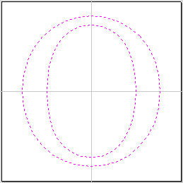
Vectors selected
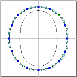
Bezier node editing
When the Node Editing tool is active the cursor changes to a Black Arrow indicating that individual points (nodes) can be edited. Nodes can be interactively moved by clicking and dragging the left mouse button on a node to select and move the node to a new position.
The shape of lines, arcs and Bezier (curve) spans can be edited by clicking and dragging on the nodes or control points to move them. Multiple nodes and control points can be selected and moved by using the multiple selection options such as the Shift key and dragging to make a selection.
If you right click on nodes or spans a context sensitive popup menu will be displayed which allows you to insert or delete points and nodes, cut the vector, move the start point etc.
Node editing vectors is a very powerful way to be able to make changes to the vectors in your part.
Smart Snapping combined with Distance Snapping or Quick Keys can give more accuracy when dragging nodes.
Interactive Selection Mode
The Interactive Move, Rotate, Scale Selection tools can be used to quickly and easily modify vectors and components.
Clicking twice on one of the selected objects and the interactive scaling, movement and rotation handles are displayed in the same way as selecting this icon. Lines, Arcs and Bezier spans will be displayed as dotted magenta lines and text and grouped objects will be displayed as solid magenta lines:
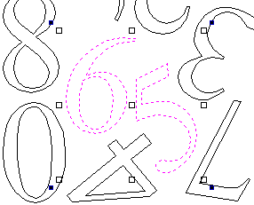
When in this mode the mouse is used to click on one of the handles which has appeared on the selected Vector/s. Each handle is used for a specific editing operation as detailed here:
| Grip point | Default Action | Keyboard Overrides |
|---|---|---|
| Middle | Move the vectors | Alt Move the selected objects in one axis |
| Corner (White) | Scale the vectors proportionally. |
Alt Scaling non-proportionally Shift Scale around the center |
| Edges (White) | Scale the vector in one axis. | Shift Scaling proportionally |
| Corner (Black) | Rotate the vectors | Alt Rotate in 15° increments |
To deselect objects,
- Click the white background unless Shift is pressed.
- Press Esc
- Right click menu ► Unselect All
Grouping and Ungrouping
Grouping objects allows you to select, move and manipulate them as if they were one entity. The process is entirely reversible by Ungrouping.
Group selected Objects
Vectors can be Grouped allowing any number of vectors to be included as a single object that can easily be selected, moved and scaled etc. The Shortcut key for this operation is G.
Grouping vectors is particularly useful for machining purposes, where different vectors will be used for a single toolpath operation. Clicking any member of the group will select the entire group.
Ungroup Selection
Ungroup a set of Grouped vectors back to its individual vectors before it was grouped.
The Shortcut key for this operation is U.
Ungroup to the group's layer
By default, when grouped objects are ungrouped they revert to the layers on which they had previously been located before the grouping operation. However this is sometimes inconvenient. For example, when you have copied a group of vectors to a new layer, it is easier for subsequent editing if the copied vectors to remain on the new layer, even after ungrouping. An alternative right-click pop-up menu command has been added to make this process easier.
A shortcut key combination is also available to provide support for both of the ungroup operations. In summary, therefore, the group and ungroup shortcut options are as follows:
| Shortcut | Action |
|---|---|
| G | Group the selected objects |
| U | Ungroup the selected objects to their original layers, sub-groups remain grouped. |
| Ctrl + U | Ungroup the selected objects to the group's layer, sub-groups remain grouped. |
| Shift + U | 'Deep' ungroup the selected objects to their original layers. Sub-groups are also ungrouped. |
| Ctrl + Shift + U | 'Deep' ungroup the selected objects to the group's layer. Sub-groups are also ungrouped. |
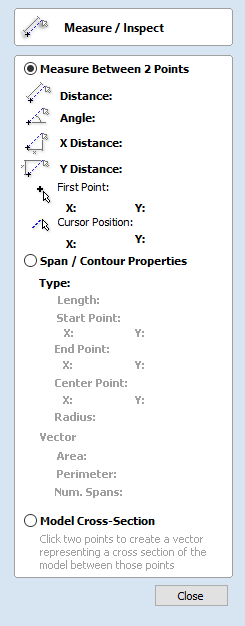
Measure Tool
The Measure tool allows you to find important information about your model or drawings.
It has two modes (please note that the options available in both modes are shown in the image here for convenience of documentation, but they are not normally available at the same time).
Measure Between 2 Points
With this option selected, you can click on two points in the 2D View and the form will report the measurements between the clicked locations
Distance
Straight line distance between the two points.
Angle
The angle (in degrees) of the line joining the two points, where horizontal is zero degrees and vertical is ninety degrees.
X Distance
The separation between the two clicked points in X only.
Y Distance
The separation between the two clicked points in Y only.
First Point
The precise X and Y coordinates of the position first clicked.
Cursor Position
The dynamically updated coordinates of the mouse cursor position.
Span / Contour Properties
This mode allows you to find precise information about the individual spans of a vector shape in 2D View. Use your mouse pointer to click on any part of the shape and the information relating to the entity you have clicked will be displayed on the form.
Type
The type of span you have clicked.
Possibilities include:
- Line
- Arc
- Bezier Curve
Length
The length of the clicked span.
Start Point and End Point
The precise coordinates of the node forming the start and end of the selected span.
Vector
Information relating to the whole vector, of which the selected span is part, is shown in this section.
Area
The total area of the selected vector
Perimeter
The total length of all the spans forming the perimeter of the shape
Num. Spans
The total number of spans in the shape.
Object Merge tools
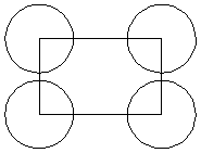
Selected closed vectors that overlap can be merged together to create a new shape. These tools consider the closed vectors to be solid areas.
The following examples begin with these five vector shapes where the rectangle was selected last.
Weld Vectors
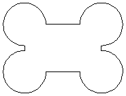
Welds overlapping vectors together to create a new shape which follows the outermost edge of all the selected shapes.
Subtract Vectors
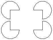
Areas in the first shapes that overlap the last selected shape are removed. In this case, the last selected shape was the rectangle, so the rectangle is cut away from the circles anywhere that overlaps.
Keep Overlap of Vectors
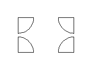
Only areas of the first selected parts (the circles) that are covered by the last selected vector (the rectangle) remain after this operation.
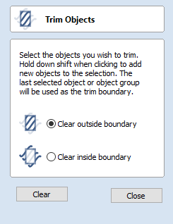
Trim Objects
The trim tool allows you to trim all the objects inside a given boundary. It is much more efficient than manually trimming all the contours with the trimming scissors, and allows the trimming of closed contours, open contours and components.
To use the trim tool first select the tool by clicking the icon on the drawing tab. You then must select the objects you wish to be trimmed first and then the object you wish to trim against last. Finally, choose whether you want to clear the area inside the boundary or outside of the boundary.
If the Clear outside boundary option is selected then all the objects that intersect this boundary are clipped, and the area outside is removed. If the Clear inside boundary option is selected, then the parts of the selected objects which lie inside the boundary are removed.
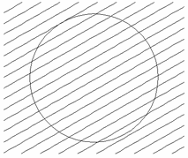
Geometry before trimming.
Select the lines first
and then the circle
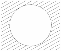
Trimmed vectors using
Clear inside boundary
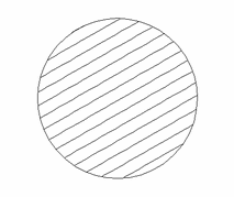
Trimmed vectors using
clear outside boundary
If you want to use multiple vectors for the trimming boundary, they must be grouped for trimming. To group a collection of vectors select the vectors, right click and choose Group Objects from the drop down menu, alternatively select all the vectors and press the G key.
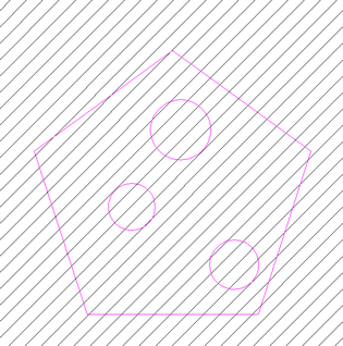
Group the vectors you want to
use as the clipping boundary

Select the vectors you wish to clip
followed by the grouped boundary,
finally trim use the trimming tool.
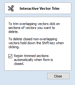
Interactive Vector Trim
The interactive trimming tool allows the user to just click on sections of vectors they want to delete.
The program finds the closest intersections either side of the clicked portion of the vector and removes the piece of the vector between the intersections. Optionally, when the form for this command is closed, the program can rejoin all the remaining trimmed pieces automatically.
Without using this tool, to remove an overlapping section of a vector, the user would need to insert extra nodes into both vectors, manually delete the intermediate sections and then manually join the resulting pieces. These operations can be performed with a single click using this tool.
When the tool is selected the cursor changes into a 'closed' scissor shape. When the cursor is moved over a vector suitable for trimming the scissors 'open' to show you can click and trim.
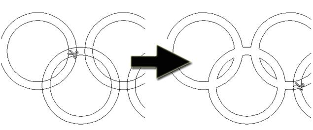
The only option on the form allows the user to select whether the program will automatically try to rejoin trimmed vectors when the form is closed. For most simple cases like that shown above with the overlapping rings, this option can be left checked ✓. If you have an example where for instance many trimmed lines meet at the same point, you may want to uncheck this option and rejoin the vectors manually.
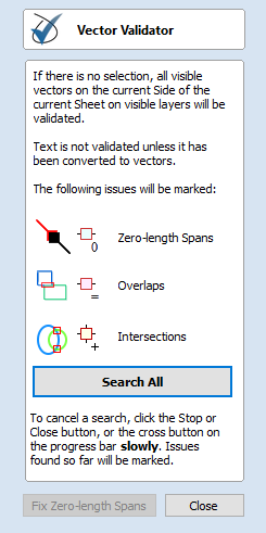
Vector Validator
The Vector Validator is intended to help find issues with contours after file imports that are stopping tool-path creation such as overlapping contours or intersections. It also indicates zero-length spans.
The Vector Validator dialog can be opened with a selection to work on. If there is no selection, all visible vectors on the current Side of the current Sheet on visible layers will be validated. The selection can be changed while the form is open.
The text on the Search button changes to show whether all vectors or just the selection are going to be searched. While searching, the button becomes a button.
To cancel a search, click the or button, or the cross button on the progress bar slowly:

that the mouse button is down when it is very busy.
Issues found so far will be marked.
The button will close the form after stopping the search.
Marks
Examples of the marks described on the form are shown below:
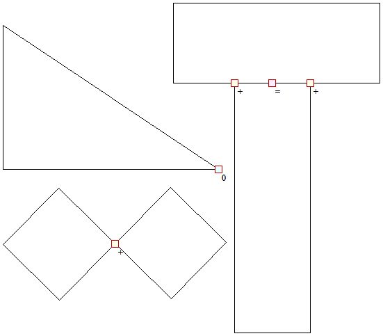
The markers do not move if you move or delete any vectors while the form is open. Markers are automatically cleared when the button is clicked or the form is closed.
Vectors can be edited (and Node-edited) while the form is open as long as a search is not in progress.
Text is not validated unless it has been converted to vectors. There is a note on the form to remind you of this.
The search will stop if 1000 issues are found.
If no issues are found a dialog will pop up saying so to confirm that the search was carried out.
If zero-length spans are found, the button is enabled. Clicking this will remove the zero-length spans and clear their markers.
Each time you run the Vector Validator it may appear to find different results first.
The order that the vectors are validated is random because the process is multithreaded; like lots of workers moving a pile of objects onto a conveyor belt that only holds one object at a time...
Several workers may want to put an object on the conveyor belt at the same time...
The final order depends on which worker got there first, as one worker will wait a little to let another place their object on the conveyor.
Which worker waits, and how fast each worker works, varies randomly because the computer may decide that you moving your mouse around is more important than validating vectors and reassign a worker to draw the mouse for a moment, for example.
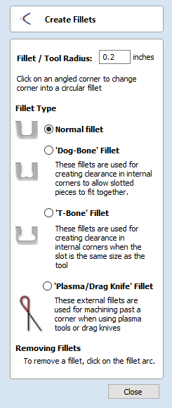
Create Fillets
Fillets or radiuses can be added interactively at points where any two spans on a contour meet. To use the filleting tool we select the icon from the drawing tab. Choose a radius for the fillet and the type of fillet you would like to use.
When the mouse cursor is near a node that can be filletted, the mouse cursor changes to show a check-mark ✓:


Not ready to fillet

Ready to fillet
When the check-mark ✓ is visible, click the left mouse button to fillet the corner.
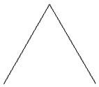
Angle Before Filletting
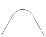
Angle After Filletting
As well as conventional radius filleting of corners, this tool includes 2 special types of filleting for corners formed by two straight lines. They will create an overcut shaped area in corners to allow clearance for another piece of material to be slotted into the part without being obstructed by material left by the radius of the tool. Below left you can see a blue piece of material fitted into a normally cut slot, this would fit no further in than the radius of the tool would allow. Below right you can see the same situation with a slot which has the Dog-Bone style corners applied to it which allows the part to fit full depth into the slot.

No Filleting

Accurate fit with Filleting
This is a very useful tool for slot-together furniture designs, model aircraft, dinosaurs etc. Below you can see a part from a slot together dinosaur assembly, on the left is the standard part and on the right is the same part with the T-Bone style fillets added to these slots. This type of fillet needs to be used when the slot is close in size to the tool diameter.
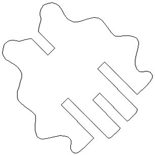
No Filleting
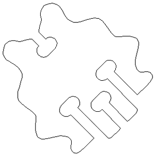
Slots Filleted
Fillet / Tool Radius
This size of this value is used to create the fillet as described for each individual type of fillet below. To create any of these Fillets you need to select the type required, then move the mouse cursor so it is over a corner between two vector spans. If it is a legitimate place to create the fillet then a check mark ✓ will show and the user can click the mouse button to create it. It should be noted that sometimes unexpected fillets will be created if the fillet size is too big for the vector shape. In that case, simply undo the change and repeat the process with a suitable fillet size.
Fillet Type
Normal fillet
This creates a standard corner fillet based on the Radius defined, typically this would be used for design purposes and not for editing a slot for fitting purposes. Below left the image shows the vector before filleting the two inside radii, on the right is the filleted version.
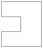
Straight Line Span Vectors before Filleting
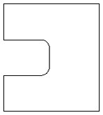
Straight Line Span Vectors After Filleting
Normal filleting can also be used on Bezier and Arc Spans, or a combination of all three span types (Straight lines, Arcs, Beziers) if there is enough space to create a fillet based on the specified Radius.
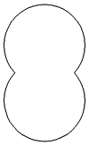
Arc Span Vectors before Filleting
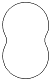
Arc Span Vectors after Filleting
Dog-Bone Fillet
This creates a circular cut-out style of fillet, the circles will be placed so the upper right part of the circle touches the original sharp corner and are created with the Radius specified. This option should not be used if the slot width and the tool are similar in size. Below left is the vector showing the slot before filleting, on the right is the filleted version using the 'Dog-Bone' option.
Vectors before Dog-Bone Filleting
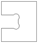
Vectors after Dog-Bone Filleting
T-Bone Fillet
This creates a circular cut-out style of fillet, the circles will be created with the Radius specified. This option should be used if the slot width and the tool are similar in size so the slot can grow out to the side to ensure there is space for them to fit. Below left is the vector showing the slot before filleting, on the right is the filleted version using the 'T-Bone' option.
Vectors before T-Bone Filleting
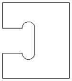
Vectors after T-Bone Filleting
The placement of the fillet is an interactive process; you can choose which side of the 'corner' the T-bone filet is placed. If you click on a 'corner' the fillet will be placed automatically on the longest side. By clicking to the side of the corner you want the fillet placed you can choose which side the fillet is placed on.
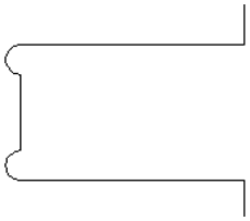
vertical edge clicked
near the corner
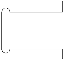
Horizontal edges clicked
near the corner
In addition, fillet arcs can be removed by simply clicking on an existing fillet arc. This works even for vectors that have been imported with filleted corners. This feature allows the user to easily change the size of fillets by clicking once to remove the existing arc and then clicking the corner to insert the new fillet. In many cases, by allowing the user to control which side of the corner the 'T-Bone' fillet is placed on means that the fillet can be hidden when the pieces are assembled.
You cannot remove fillet arcs from .eps files as they do not contain arcs and only contain straight lines and Bezier Spans.
Removing Fillets
Fillets can be removed in the same way that we add fillets: move the cursor over the fillet that you wish to remove.
If this fillet can be removed then the cursor shows a cross to indicate that it is possible to remove a fillet:

Clicking removes the fillet:
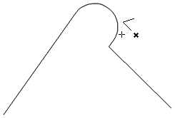
Before removing fillet
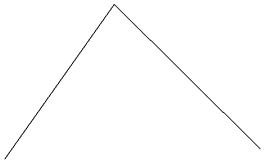
After removing fillet
When removing fillets the software does not store what kind of geometry the fillet was created from. It always defaults to using straight lines to return the fillet to a sharp corner. As such if the fillet is across multiple spans or is derived from arcs or Bezier curves then it will not go back to its original state and instead it will remove the radius and extend two straight lines to create the new corner. Below are images that show this effect, the first set show the whole vector and the second show a section of the vector in node edit mode to help show the difference. If the fillet was created recently then it may be possible to use the Undo command to return it back to its original geometry.
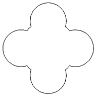
Original Vector
Vector with Fillets
New Vector after Removing Fillet
Original Vector in Node Edit Mode
Vector with Fillets in Node Edit Mode
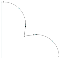
New Vector after Removing Fillet
in Node Edit Mode
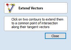
Extend Vectors
This tool allows you to extend two vector lines to their common point of intersection. The tool form is rather sparse, but that is because all the action occurs directly in the 2D View.
With the Extend Vectors tool active, moving the mouse pointer over the ends of open vector shapes (without clicking) will highlight a dashed preview extension line from that shape. The line will change dynamically as you move the mouse over the end spans of different open shapes. Clicking with the left mouse button at this point will set it as the target line to extend and the magenta line will remain visible.
The mouse can now be moved over existing spans along the length of the preview extension line, or over the end of another shape to create a second, intersecting, preview extension line.
Clicking on any of the intersection points indicated by the mouse cursor will extend the initial shape to that point and complete the operation.
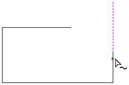
First click creates a preview extension line
from the selected vector span.
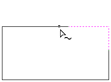
Moving the mouse over another span
will display a second preview extension line
to the point of intersection.
Click the line to apply this change.
The tool can be closed at any time using the button on the form. Right-clicking in the 2D View will reset the tool so that it is ready to select another target line to extend.
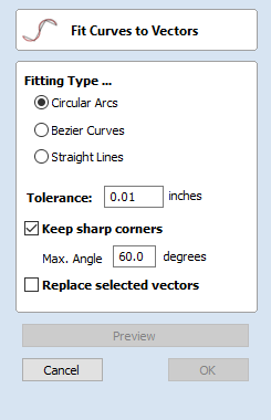
Fit Curves to Vectors
This function allows the user to fit arc, Bezier curves or straight lines to selected vectors. The newly created vectors will be approximated based on a user defined tolerance. Using this function can aid with smoothness for some toolpath options and also help to simplify data for modeling purposes.
The Curve Fitting function can be accessed from the Edit Objects area of the Drawing Tab, the Edit Menu ► Curve Fit Vectors in the Main Menu or by using the short-cut-key combination Ctrl+F.
Fitting Type...
Circular Arcs
Checking ✓ this option means the selected vectors will be approximated using arcs:
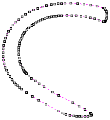
The vector before fitting
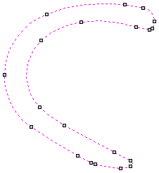
The same vector fitted with arcs
Bezier Curves
Checking ✓ this option means the selected vectors will be approximated using Bezier curves.
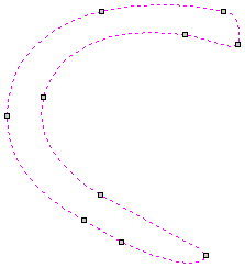
The same vector
fitted with bezier spans
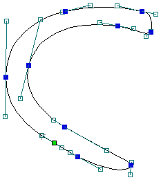
The same bezier spans in Node-edit mode
Straight Lines
Checking ✓ this option means the selected vectors will be approximated using straight lines.
The vector before fitting
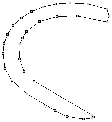
The same vector fitted with straight lines
Tolerance:
The value which is set in the Tolerance area determines how closely the original vectors will be approximated. The newly created, Arcs, Beziers or Lines will be generated within a distance of the original vector which is plus or minus the specified Tolerance value. The smaller the value the closer to the original the new data will be but it will also mean more data points will be used. A larger Tolerance will not be as accurate to the original but will have less data points. The diagram below shows the curve fitted to two straight lines with the max possible distance between them defined by the Tolerance set. The tolerance is the distance indicated with the red arrow:
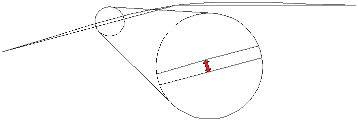
The same vector fitted with straight lines
Keep Sharp Corners
Checking ✓ this option will make the Curve Fitting routine keep sharp corners which have a difference greater than the Max Angle value specified. Any corners where the difference in angle is less than this value will be modified within the specified tolerance. The images shown below demonstrate how this works. The first image shows a set of straight lines before curve fitting with the angles shown between the spans. The second image shows this after curve fitting with the Keep sharp corners set with a value of 20°. You can see the two lines which were under the 20° difference have had a curve fitted between them but the other corner which has been retained as the original angle is greater than 20°.
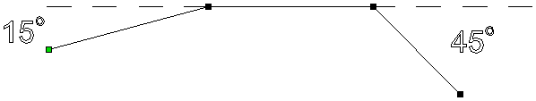
Initial Vectors
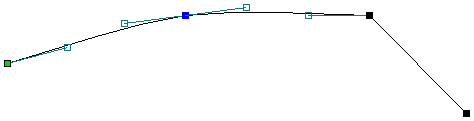
Result after Keep Sharp Corners
Replace selected vectors
Checking ✓ this option will delete the current vectors and replace them with the new curve fitted vectors. Un-checking it will keep the original vectors as is and in addition create new curve fitted vectors. The new vectors will always be created on the currently selected Layer.
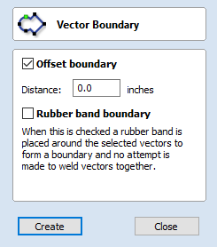
Vector Boundary
The Vector Boundary form allows you to create boundaries around selected vectors.
You can offset the boundary outwards and optionally create convex or 'Rubber band' boundaries.
Offset Boundary
When this is checked ✓ the created boundary is offset outwards by the distance specified.
Rubber Band Boundary
When this is checked ✓ the created boundary is the result of stretching a rubber band around the currently selected vectors.
The images below demonstrate the difference between the two types of boundary that the form creates. The picture on the left illustrates the standard offset output and the one on the right shows the result when Rubber band boundary option is checked ✓.
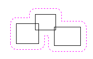
Offset Boundary only
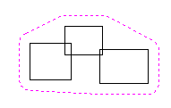
Offset Boundary and Rubber Band together
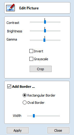
Edit Picture

The Edit Picture form allows you edit the properties and border around the selected bitmap.
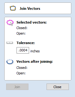
Joining and Closing Tools
| |
|
|
|
The icons to join and close vectors are located under the Edit Vectors section of the Drawing Tab.
Join Open Vectors
This icon opens the Join Vectors Form
Open vectors are automatically identified and closed or joined to other vectors where the end points lie within the user definable tolerance.
Join/Close vectors with a straight line
Join with a Line finds the closest end points on 2 selected, open vectors and joins with a straight line. Close with a Line closes a single open vector with a straight line between its two end points.
Join/Close vectors with a smooth curve
Join with a Curve finds the closest end points on 2 selected, open vectors and joins them together with a smooth curve.
Join/Close by Moving End Points
Join Moving End Points finds the closest end points on 2 selected, open vectors, calculates the mid-point between them and moves the end points to this position.
The Offset and Layout Tool Group
Click on an icon to learn more about it:
| Offset and Layout | |||||
 |
 |
 |
 |
||
This tool group includes tools to create offset versions of existing objects or to layout objects automatically.
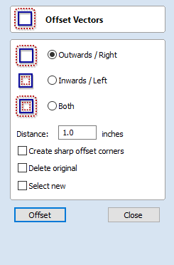
Offset Vectors
Selected vectors (open or closed) can be offset either inwards or outwards to create new vector shapes that might be useful for edge patterns or borders etc. To offset a vector shape, use the following steps:
- Select the vectors to offset
- Select the required direction - Outwards / Right or Inwards / Left
- Enter the Distance
- Click the button
Options
The offsetting options are slightly different in their behavior depending on whether the vector to be offset is open or closed. See below for more information.
Create sharp offset corners
Will retain any sharp corners in a design.
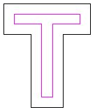
Offset with Sharp Corners on
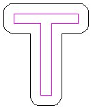
Offset with Sharp Corners off
Offsetting Open Vectors
When offsetting open shapes, the options are either to the Right or Left side of the selection. The direction of open vector(s) is very important as this is used to decide the right and left side of the selection. Selecting Node Edit mode (pressing N on the keyboard) will display a Green node at the start of the vector. Looking along the vector(s) from the green node indicates the direction and the image below shows offsets to the left and right of an open vector.
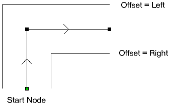
Notes
Square Offsetting a very acute (included) angled sharp corner will result in the corner point being positioned a long way from the original geometry, often off the material or cutting through other shapes in the design. To stop this happening Cut2D Laser Desktop checks that the distance for the new calculated offset point is less than 5 x the offset distance away from the original corner point.
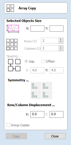
Array Copy
This tool will automatically create copies of the selected object and lay them out in a grid pattern. The grid size is determined from the number of row and columns requested and the spacing of the object copies can be set directly as a gap distance, or in terms of an offset distance between each copy's position.
Selected Objects Size
Reports the current size of the selection that you are intending to block copy. This is for information only, but the values can be selected, copied and pasted to use in other calculations.
Rows and Columns
These options specify how many rows and columns of the selected object to create. The total number of copies made will be X multiplied by Y.
Spacing...
There are two ways to specify the spacing between elements in array:- Gap
- The X and Y fields will be used to specify the gap between edges of each object copy.
- Offset
- The X and Y fields are used to define the offset of the position of each object copy, relative to the preceding one.
This example shows a sign blank copied to create a 3 x 3 array.
3 Rows x 3 Columns with a Gap of 0.3 inches between each object:
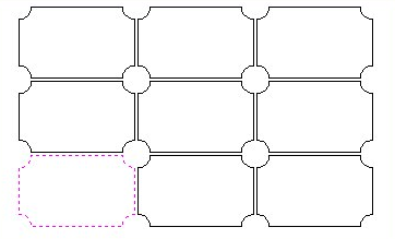
Symmetry...
The symmetry area of the form gives you the ability to mirror and rotate objects. This allows for more advanced pattern making, by default the block symmetry form is set so there is no symmetry or rotation. To alter the pattern you can simply press the block symmetry buttons to create your desired pattern.
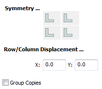
Default Block Symmetry Options
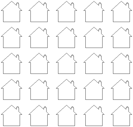
Resulting Pattern

Horizontal Symmetry Applied to Row Above
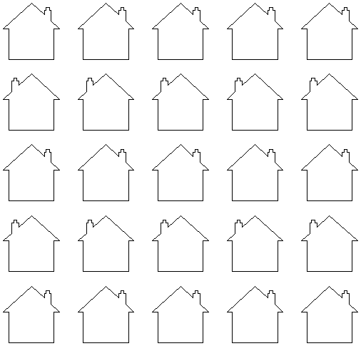
Resulting Pattern
Row/Column displacement...
Entering values in the Row/Column displacement allows you to move a row or column by the value specified.
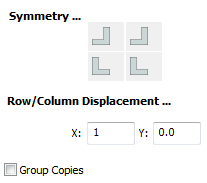
Row Displacement of 1
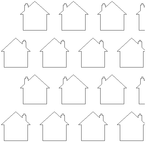
Resulting Pattern
Group Copies
Having this option checked ✓ will group the objects that you have created in the form when you hit the button.
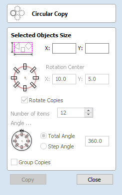
Circular Copy
This tool will automatically create a repeating pattern by making copies of the selected object and positioning them around a full or partial circle. The number of copies to be made can be entered directly.
Rotation Center
This is the absolute XY coordinate around which the objects will be rotated when copied and pasted. The default Rotation point is the middle of the selection. You can set the rotation center coordinates explicitly using the X and Y edit boxes on this form or by clicking the selected geometry to show the transform grips, then double-clicking the center one to show the pivot-point and dragging the Pivot Point handle associated with the selection in the 2D View:
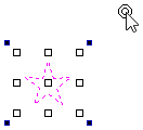
Rotate Copies
This option controls whether the copied objects are each rotated as they are placed around the circle, as shown in the diagrams below. If this option is selected, each copy is rotated according to its position on the circle. If the option is not selected then each copy maintains the orientation of the originally selected object.

Rotate Copies selected

Rotate Copies not selected
Angle
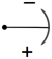
A Positive Step Angle pastes the copies in a clockwise direction.
Total Angle
With this option selected the number of items is divided into the Total Angle to give the incremental angle between each object.
Step Angle
With this option selected this angle is used to copy the selected vector(s) by this angle x the number of Items.
Copying Multiple Vectors
The result of one array copy can be used for another to create more complex patterns, this one being used for an engraving. The rotation point has been set by double-clicking the centre grip, then dragging to the desired location:
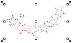
Copying multiple vectors
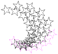
Result of Copying Multiple Vectors
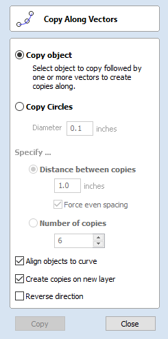
Copy Along Vectors
This tool automatically creates repeating patterns of objects by placing copies of them along the length of one or more selected vectors. The tool allows any existing object to be used but it also has an option specifically for the creation of circles, which is a common design element for patterns of this sort.
To make copies of an existing object, select the item to copy, then holding a Shift key down to facilitate multiple selection, select the vector curve or curves you wish to paste the item along. Make sure the Copy Object option is highlighted and click .
If you wish to create circles, then you simply need to select one or more vectors along which the circles will be created. Ensure the Copy Circles option is highlighted and click .
Copy Object
Any shape vector or group of vectors can be copied along a curve or curves. The first vector or group of vectors selected is the object that gets copied multiple times along the curves.
Copy Circles
Enter the diameter of the required circles
Selected Vectors
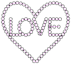
Circles Copied along curves
Distance between copies
This is the distance along the selected curve between each pasted vector. The Force even spacing option ensures that objects are pasted at the end points on the curve(s). If this option is not selected the pasted objects will be placed at the specified distance and may not match the exact length of the curve.
Number of copies
Selecting a specific number of copies automatically sets the specified number of copies along the entire length with an even spacing between them.
Align Objects to curve
With this option selected the pasted objects are automatically aligned 'normal' or perpendicular to the curve they are being copied onto. If this is not selected, the copied objects stay in the orientation of the original.
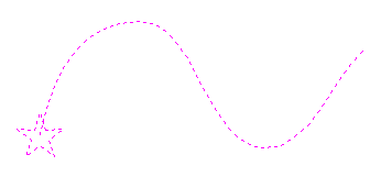
Selected Vectors
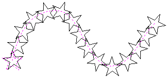
Stars Copied along the curve
Create Copies on new layer
This option creates the multiple copies on a new layer making it much easier to select and organize the resulting vectors for machining purposes etc.
Reverse Direction
If your copies appear upside down, this option will perform the copy operation in the opposite direction along the selected vectors and the resulting copied shapes will be created the other way up.
Layers
Vectors, Bitmaps can be assigned to different layers. All the objects assigned to a layer can then be simultaneously selected, labeled, colored, temporarily hidden or even locked (to prevent accidental editing) using the Layer Management tools. Even for relatively simple designs, organizing the elements of your artwork onto layers can make managing your project much easier.
There are no specific 'rules' on how to use the layers -there are many ways to organize your design and these are likely to vary between individuals and even between different jobs. The 'meaning', therefore, of the layer organization in any particular project is entirely flexible. Some common examples of layers include:
- Organizing artwork according to the toolpath strategies to be created.
- One layer for shapes to be profiled, one for those to be pocketed, one for drilling etc.
- Coloring different parts of the design to reflect different parts of the finished piece.
- Hiding or locking geometry used as guides or temporary stages in the construction of the final design.
Managing Layers
You can access the tools needed to manage layers from two locations: the Layer Control on the View Tool Bar, and the Layer List on the Layers tab.
The Layer Control on the View Toolbar
A Quick Access Layer Control is conveniently located above the Views in the View Toolbar. This tool provides a pop-up Layer List, from which you can quickly change the selection of the active layer, add a new layer, or modify the properties of any existing layer. When you have finished, click anywhere outside of the Layer List window and it will cause it to close.
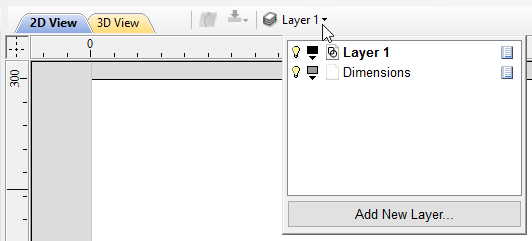
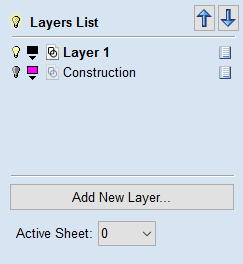
The Layers Tab
To get a complete overview of the current layer structure of your artwork while you are working, or to carry out more extensive organization of the layers, you can also use the Layers tab. The Layer List is identical in both the Layer Control and the Layers tab, but the latter can control layer ordering and be left visible, pinned or even undocked, while you continue to work on the artwork itself.
The Layers Tab makes it very easy to work with complex designs giving quick access to all of the layer control options.
From this tab you view all the layers in your current job and modify their properties (such as visibility and color). You can also create, delete, re-order or rename them.
Most of the commands associated with layers can be accessed by right-clicking a layer in the list, or by clicking on the Pop-Up Menu icon  to the right of the layer name.
List Item Command and Icons
Each layer in the list has five elements:

Status Icon
The leftmost icon indicates whether the layer is currently  visible or
  hidden.
Click on this icon to toggle the visibility of the layer.
hidden.
Click on this icon to toggle the visibility of the layer.
The presence of a padlock  shows that the layer is locked and cannot be accidentally edited.
Right-click the layer in the list and select the Unlock command to alter this.
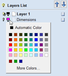
Layer Color
The color swatch can be used to color all the vectors on a layer.
Click on the swatch icon  and select a pre-set color from the color selector dialog, or choose to create an entirely custom color.
Layer Content
The layer content icon will be grayed-out as an additional indicator that the layer is not currently visible.
 a blank white sheet indicates that the layer does not currently contain any objects or vector geometry.
If you import files from 3rd party CAD drawing packages via DXF or DWG format it is common for the file to include empty layers.
This icon allows you to identify these empty layers and delete them.
a blank white sheet indicates that the layer does not currently contain any objects or vector geometry.
If you import files from 3rd party CAD drawing packages via DXF or DWG format it is common for the file to include empty layers.
This icon allows you to identify these empty layers and delete them.
then use any layer's Pop-Up Menu icon
to select the Merge Visible command.All the visible layers will now be merged into a single layer, which can be deleted with a single operation.
Layer Name
To change the name of a layer, you can double click on this part of the layer item in the list to trigger in-situ editing. This works in the same way as file renaming in Windows Explorer. Alternatively you can right-click or use the layer's Pop-Up Menu icon to select the Rename command.

Pop-up Menu
Click the pop-up menu icon for access to Activate, Lock, Insert, Delete and Merge layers as well as further ways to choose which layers to show and hide.
Additional Buttons and Icons
Show All / Hide All
The visibility icon to the left of the Layers List heading at the top of the Layers Tab will toggle the visibility of all the layers in the list.
If there are both hidden and shown layers, this icon is shown as a dim lamp: 
Clicking the dim lamp will show all layers and change to icon to a lit lamp: 
Clicking the lit lamp will hide all layers and change to icon to an off lamp: 
More options for setting the visibility of multiple items are available from the Pop-Up Menu for each layer under the Show and Hide menu headings.
Select All on a Layer
Double-clicking on a layer in the Layers List will select all the objects on that layer. Alternatively you can choose the Select Layer Vectors command from the layer's pop-up menu.
Layer Ordering Arrows
Adjacent to the Layers List heading label are two arrow buttons. These move the selected layer up or down in the Layers List. This can be important to set the drawing order of objects that might otherwise obscure one another (specifically Bitmap Previews). Objects on the top layers in the list are always drawn before objects in the lower layers and will, therefore, be 'underneath' them in the 2D View. You can use the Layer Ordering Arrows to resolve this issue.
Add New Layer
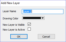
New Layers can be added using the button.
Alternatively a new layer can be created directly from the 2D View by right-clicking an object and selecting either the Copy to Layer ► New Layer... or Move to Layer ► New Layer...
The dialog for adding the new layer is displayed with options to specify the name and color of the vectors on the new layer and an option to indicate if the new layer should be visible.
Layer Name
It is always preferable to take the opportunity at this stage to give your new layer a meaningful name relating to its content or purpose. Later on this name will make it easier for you to manage your layers as your design becomes more complicated.
Drawing Color
All the vectors on this layer will be colored according to this setting. This can be a very useful way of distinguishing between the vectors that are on different layers, directly in the 2D View.
New Layer is Visible
With this option checked, ✓ the new layer will automatically be visible as soon as it is created.
New Layer is Active
With this option checked, ✓ the new layer will automatically become the active layer and any subsequent vector creation or manipulation will occur on this new layer.
Insert New Layer
An even quicker way to add new layers is via the Insert Layer command from a layer's right-click Pop-Up Menu. This command will create a new layer above the selected layer which will be visible, unlocked and colored black. After creation the new layer item's name is ready to be immediately edited by typing a new name in.
Moving Layers
Objects on any layer can be moved onto another layer by right-clicking the object in the 2D View and selecting Move to Layer ► ... from the pop-up menu.
Toolpath Operations
- See Also:
- Toolpaths Overview
- The Toolpath List
Click on an icon to learn more about it:
| Toolpath Operations | |||||
 |
 |
||||
 |
 |
 |
 |
 |
Toolpath Editing Tools |
 |
 |
Estimation, and Saving | |||
Toolpaths
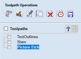
The ultimate purpose (in almost all applications) of Cut2D Laser Desktop is to allow you to generate toolpaths which can be run on a CNC machine to machine the finished part in the material of choice. This requires, at a minimum, some vectors to describe the area to which a toolpath will be limited to. The process for creating toolpath is as follows:
Prepare vectors for machining
Optionally organize the vectors you will be using for machining onto appropriate layers.
Set up the Material
Check the overall material size (Job Setup) to ensure it matches or exceeds the size of the finished product.
Use the Material setup form from the Toolpaths Tab to set the reference Z datum for the part relevant to the CNC machine.
Create the Toolpaths
Work through the toolpath strategy icons you wish to use to machine the job to calculate all the required toolpaths.
Save the Toolpaths for the CNC machine
After choosing the appropriate Postprocessor from the list, the toolpaths can be saved in a format which is ready for the CNC to cut. Depending on the toolpaths calculated and the options the Postprocessor/CNC you are using supports, you may be able to save a single file or it may need multiple files to be saved - one for each tool type.
All the stages will be covered in the supplied Tutorial videos that include Machining. These will be covered in the next section.
Additional Toolpath Tab Features
Switch to Drawing Tab

Closes the Toolpath Tab (right hand screen form) and opens the Drawing Tab (left hand drawing form)
The pin icon is described in the section: Accessing Auto-hidden tabs
Toolpath Summary Area
When a toolpath is selected from the Toolpath list with no other function being used in the Toolpath Tab a text summary of the toolpaths settings is shown in the body of the Toolpath Tab below the icons. This is a very useful way to recall settings for a toolpath without opening it.
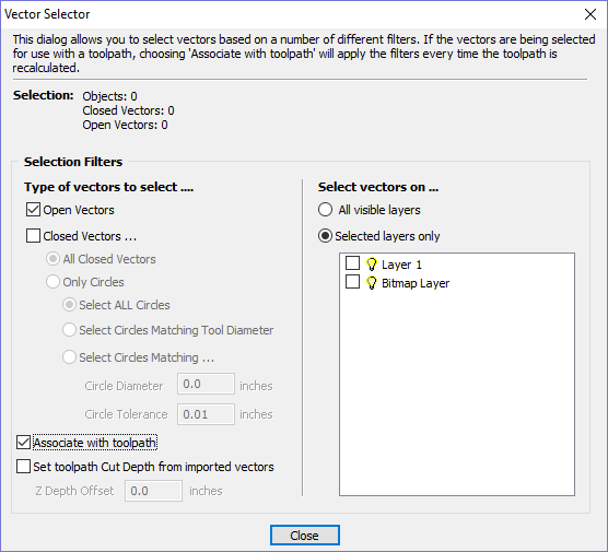
Vector Selector
This tool allows you to easily select vectors which meet a set of criteria, such as open, closed, circular and also matching constraints based on layers. The dialog can be accessed from the Edit ► Vector Selector menu item, or from the button on each toolpath form. When the command is executed the dialog shown is displayed.
The dialog is used to configure a set of 'filters' that determine which vectors will be selected. A filter is enabled by clicking on its check box, or selecting a 'radio button' option, the current selection will be updated with all the objects in the file which match the current filter options.
Generally you will start at the top of the dialog and work downwards, specifying more and more explicit filters to determine the required selection exactly.
The simplest option is just to use the form to Select Closed Vectors in the job or Select Open vectors (you can specify both, in which case all vectors will be selected as long as they are on a visible layer).
The most common way to use the Vector Selector is to select all the vectors on a given layer as shown in the screenshot of the dialog below.
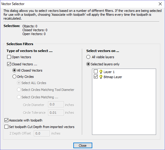
In this example, the dialog has been used to select All Closed Vectors on the layer with the name Pocket.
Selection
The Selection: section at the top of the dialog is continuously updated to show the results of the current filter and the 2D view is also updated to show what is currently selected. The Objects: entry shows the total number of objects selected, if these objects include Text or Groups, this number may be less than the total of Closed and Open vectors displayed on the following line. For instance, a block of text is one object but will usually consist of many closed vectors. If a group contains both open and closed vectors, it will be selected as matching both Open and Closed filters.
Geometry Filters
The Geometry Filters section is used to specify constraints on the type of vectors to select. You can choose to select open vectors and/or closed vectors. Instead of selecting All Closed Vectors, the dialog can be used to select Only Circles and can even be used to specify an exact diameter and tolerance for the circles to be selected. This can be very useful for selecting vectors for drilling toolpaths, particularly if the vectors have not already been sorted into layers.
Layer Filter
The Layer Filter section allows you to pick one or more visible layers on which to select vectors which match the geometry filter. Alternatively, the All visible layers option disables the filtering by layer and selects all vectors which match the geometry filter regardless of the layer they are on, as long as that layer is visible.
The Associate with toolpath option will be explained in the next section.
Advanced Toolpath Templates
By associating a template with the result of a Vector Selector filter, we can make a template to automatically select the vectors it is intended to machine. A simple case would be to create a template which consisted of a Pocketing toolpath set up to machine all closed vectors on a layer called Pocket. After loading this template into a new job and choosing Toolpaths ► Recalculate All Toolpaths , the toolpath would be recalculated automatically selecting all closed vectors on the layer called Pocket.
The advanced templates are created by selecting the vectors for a toolpath using the button on the toolpath form. When a toolpath form is first opened, the Vector Selection: section on the form will show that vectors are being selected manually as shown below...
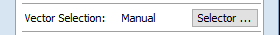
Pressing the button will display the Vector Selector form as shown previously. After making your geometry selection and before you close the form, select the Associate with toolpath option on the form as shown below.
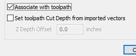
After the Vector Selector form closes, the Toolpath form will indicate that Vector Selection is now 'Automatic' as shown below...
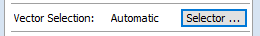
When you re-calculate or edit a toolpath that has the Vector Selection mode set to automatic, the vectors which match the filter when the toolpath is re-calculated or edited will be selected. To cancel the Automatic vector selection mode, you can just select the vectors to machine normally with the mouse, or use the button to bring up the Vector Selector dialog again (the settings are remembered) and uncheck the Associate with toolpath option.
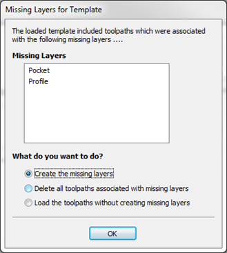
If toolpaths with the Vector Selection mode set to Automatic are saved as templates, these setting are saved with the template. When the template is re-opened and the toolpaths recalculated, they will automatically select all vectors which match the filters specified with the Vector Selector for that toolpath.
If you load a toolpath template which has toolpaths associated with layers which don't exist in the current file, the Missing Layers for Template dialog will be displayed. It lists all the missing layers and offers you the choice of having them created automatically, deleting toolpaths associated with missing layers or just loading the toolpaths as is.
Choosing to allow the dialog to automatically create the missing layers allows a toolpath template to be used to create 'standard' layers for machining operations and load the toolpaths ready to be calculated. All you then need to do is move vectors to the appropriate layers and recalculate all the toolpaths.
Choosing the Delete all toolpaths associated with missing layers option allows you to create a single template with many toolpaths and have the ones which aren't appropriate to the current job automatically deleted.
Toolpath Editing Tools
Edit Toolpath
This option is used to modify an existing toolpath. Click to select a toolpath in the list then click the edit option to open the form.
The vectors associated with each toolpath are automatically remembered, so editing a toolpath will automatically select the vectors in the 2D window.
Make the required changes to the toolpath parameters Click the Calculate button to update the toolpath
A toolpath can also be edited by double-clicking on its name in the toolpath list.
Duplicate Toolpath
The Duplicate Toolpath option creates and adds a copy of the selected toolpath to the Toolpath List. An index number is automatically added to the name of the new toolpath. For example:
Cut out - 1/4 inch End Mill will create a copy with the name Cut out - 1/4 inch End Mill (1)
Copying externally generated 3D toolpaths (as, for example, from PhotoVCarve) will also create a duplicate grayscale thumbnail image in the 2D View, which can then be used to position the toolpath within your job.
Delete Toolpath
This tool is used to delete calculated toolpaths from the Toolpath List. Simply select the toolpath to be deleted and click the Delete Toolpath button to remove it.
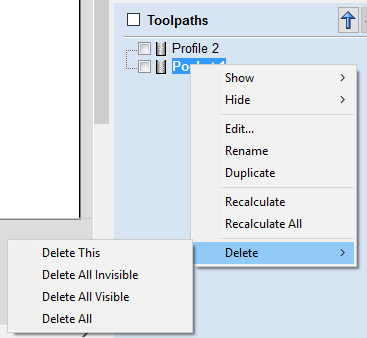
Alternatively you can delete one or multiple toolpaths in the Toolpath List by right mouse clicking on a toolpath. Then from the drop-down menu click on the option. This will present the options as shown in the image: Delete This, Delete All Invisible, Delete All Visible, Delete All.
Delete This will delete just the toolpath whose name you right mouse clicked on.
Delete All Invisible will delete any toolpaths in your Toolpath List that do not have a check-mark ✓ next to their name and are therefore currently not visible in the 2D or 3D Views.
Delete All Visible will delete any toolpaths in your Toolpath List that have a check-mark ✓ next to their name and are therefore currently visible in the 2D or 3D Views.
Delete All will delete all the toolpaths in your Toolpath List.
If you have incorrectly deleted a toolpath (or multiple toolpaths) then you have the option to Undo the toolpath(s) deletion via the command on the drop-down menu, the Undo icon on the Drawing Tab or the Undo shortcut key combination Ctrl + Z.
Recalculate All Toolpaths
This command forces a recalculation of all the toolpaths in the Toolpath list. It is useful when the artwork used by the toolpaths has been modified, or the material block settings have changed.
The Tool Database
The Tool Database is used to make cutter management and selection very quick and easy, and reduces the possibility of programming jobs with incorrect cut depths and speeds and feeds. The Tool Database is accessed from the button every time you create a new toolpath and allows pre-defined tools and settings (speeds, feeds, stepover etc.) to be selected from a list.
New tools can be added, copied from existing tools, deleted and organized. All of the cutting parameters are stored in the database.
Opening the tool database
To access the Tool Database you can click on the Database icon on the Toolpaths Tab:
Alternatively, select Toolpaths ► Tool Database from the main menu bar.
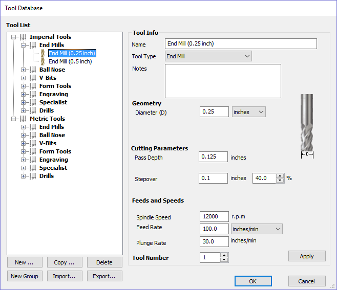
A window similar to that shown will appear displaying a list of the tools that are currently defined on the left and the parameters for the currently selected tool from the list over on the right. Below this image is a list of all the actions that can be executed from this dialog:
Tool List
The Tool List is located on the left-hand side of the Tool Database. Click on items in the list to see or edit their properties using the Tool Info section of the database window. The Toolpath list is arranged hierarchically to allow you to organize your tools according to common properties or use.
You can click and hold down the left mouse button to drag items up or down in the list. If you drag them into a tool group, they will be placed inside the group.
Tooltip of group hierarchy
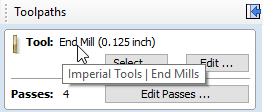
When a tool is selected within a toolpath strategy page, the tool name does not always provide enough information for you to know whether the tool's settings are appropriate. It is always possible to click Edit and see the full set of the tool's properties and settings. However, if you hover your mouse over the tool's name, a tooltip will pop-up telling you what the location of this tool was in the tool group hierarchy when it was added to the toolpath strategy. This can be extremely useful for quickly distinguishing between tools in your database that have similar names, but have been grouped according to their properties.
Adding a New Tool
Selecting creates an empty tool in the list that can have any user definable name.
Copying a New Tool
Copy adds a duplicate of the selected tool to the list and prefixes the original name with (1). Edit the Name and properties for the new tool and click the Apply button to save the changes to the list.
Deleting a Tool
Deletes the selected tool from the database.
Creating a new tool group
Click on the add button then give your new group a name and press to add it to the database. Click and drag tools from the database over the top of the newly created group icon in the tool database tree to add them to the group. Alternatively, select the group and then click the button to create a new tool directly within the selected group.
Importing and Exporting tools
Individual tools or complete tool group hierarchies can be saved to disk using the button. Similarly, you can import previously saved tools, groups or even entire tool databases using the button.
Tool Info
When a tool or group is selected in the Tool List, its properties are displayed in the Tool Info section on the right-hand side of the Tool Database.
Here you can modify any of the properties of the currently selected Tool or Group. Click the button to save the changes to the Tool List.
Name
Use this field to enter a suitable name to describe your cutters.
Tool Type
Various cutters can be specified in the database.
V-Bit
Engraving
Tapered Ball Nose
When specifying the geometry for a tool, the angle specified is different for V-Bit and Engraving Tools.
V-Bit Tools are defined using an Included Angle (A)
Engraving Tools are defined using the Half Angle (A) and the Flat Diameter (F)
Ball Nose

End Mill
Radiused End Mill
Form Cutters
Diamond Drag
Drills
Notes
The tool notes section simply allows you to save any additional text descriptions, special instructions or relevant information you may require, within your tool definition.
Geometry
Diameter
The diameter of the tool in either inches or mm. The tool image will indicate where this dimension is taken from. If you change the tool diameter but do not change the tool name then you will be warned.
Cutting Parameters
Pass Depth
The maximum depth of cut the tool can cut. The Pass Depth controls the number of z level passes that are calculated for a toolpath. For example, creating a pocket 1 inch (25.4 mm) deep using a tool that has a Pass Depth of 0.25 inches (6.35 mm) will result in the toolpath making 4 passes.
Stepover
The distance the cutter moves over when doing area clearance cutting. For example, when raster machining the cutter will machine along the X axis, stepover in the Y direction and return parallel to the first line of cut. The greater the stepover the faster the job will be machined, but this must be balanced with the material being cut and the tooling being used, to ensure that the tool does not break.
When stepover's greater than 50% of the cutter / tip diameter are used the software automatically adds 'Tail' moves in the corner regions of toolpaths to ensure material is not left on the job for offset based strategies. When using V-Bit Tools, the Stepover fields automatically change to use the following options.
Final Pass Stepover
The distance the cutter moves over when finish machining and is usually set to be a relatively small distance to produce a smooth surface finish on the job.
Clearance Pass Stepover
Only used when a V-Bit tool is being used to rough machine at multiple Z levels down to a specified flat depth. This stepover can be much larger than the Final Pass Stepover because the tool is only rough machining material away. Increasing the Clearance Pass Stepover will reduce the machining time, but you must be careful to ensure it is not too great for the material being cut.
Feeds and Speed
Spindle Speed
Speed of tool rotation, specified in revolutions per minute
Feed Rate
The surface cutting rate at which the cutter is moved in the material. The units can be specified in distance per second or minute.
Plunge Rate
The cutting rate at which the cutter is moved vertically into the material or during ramping moves. The units can be specified in distance per second or per minute.
Tool Number
This is the number of the tool needed to machine the job. When using a CNC machine with an Automatic Tool Changer (ATC), it is critical that the correct tool required to cut the job is located in the corresponding carousel location.
Using Form Cutters
Form Cutters can be added to the Tool Database so that industry standard Ogee and Round-over type cutters, plus user definable custom shapes can be used for edge profiling and decorative carving. Examples of these types of cutters and the kind of cuts they can be used for are shown in the images below:
Round-over
Ogee
Profile Cutting Strategy with Form cutter
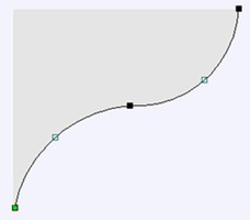
Adding your own custom form cutters
Adding a Form cutter to the Tool Database is straightforward and the procedure is,
Before opening the tool database, draw to exact scale the Right side of the cutter geometry in the 2D Window Use the Node Editing tools to create the arcs and curves etc.Only draw the Right-hand side of the cutter geometry to the correct size and scale as shown in the image above.
The shape can be a combination of Lines, Arcs and Bezier spans. With the vector Selected open the Tool Database (using the command icon on Toolpaths tab or from the main menu, Toolpaths ► Tool Database In the Tool Database window, click Select Form Tool
The selected geometry will be imported and a profile displayed in the window.Give the Cutter a meaningful name and enter the cutting parameters - speeds and feeds etc. Click the button to save the new cutter into the database list so it can be used at any time.
Estimating Machining Times
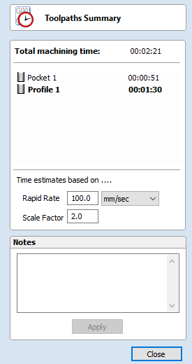
This option estimates the machining times for all calculated toolpaths based on the feed rates specified for each tool. The estimates for individual toolpaths plus the overall machining time of all visible toolpaths are calculated using the user defined Rapid Rate moves and Scale Factor.
Times
The estimated machining times are displayed in Hours: Minutes: Seconds
Rapid Rate
The maximum feed rate at which the machine runs for rapid moves, typically specified using a G0 or G00 move
Scale Factor
The nature of different styles of toolpaths means that they may be simple 2D cuts or require simultaneous 3-axis moves, the more complex the toolpath then the more chance the CNC machine may not actually achieve the programmed feed rates. This can be compensated for by multiplying the times by the Scale Factor.
The inaccuracies generally come from the acceleration / deceleration of the machine. If the program tells a machine to move at 200 inches / min along a 200 inch straight line the machine will probably take pretty close to a minute.
If instead of a straight line we ask the machine to cut say a gear wheel with a total circumference of 200 inches, the machine is likely to take considerably longer. This is because the machine will have to slow down to go around the tight curves of gear tooth profiles and will probably never reach its programmed speed before having to slow down again for the next change in direction.
The scale factor in the program lets you approximate this slowdown for your machine, but it will vary depending on the type of work you are doing. Many people will use one scale factor for simple 2d work and another for 3d or VCarving. The best way to calculate it is just to take a note of estimated and actual machining times of a period of time.
If a job actually takes 6 minutes to cut and the estimate was 3 minutes, the scale factor would be set to 2 (actual time / estimated time = 6/3).
For machines where the controller provides an estimated machining time, these should be more accurate as the controller can determine where the machine is accelerating / decelerating and take account of this.
Saving Toolpaths
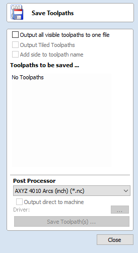
This option allows toolpaths to be saved in the appropriate file format needed to drive the CNC machine. Toolpaths can be saved as individual files for each tool used or as a single file containing multiple toolpaths for CNC machines that have automatic tool changers.
Individual Toolpaths
CNC machines that require the tooling to be changed manually will typically need a separate toolpath for each cutter used. The procedure for saving this type of toolpath from Cut2D Laser Desktop is to:
- Select the toolpath to save from the Toolpath List
- Click on the Save option and the Save Toolpaths form is displayed.
- Select the correct Postprocessor for the CNC machine from the pull-down list
- Click the Save Toolpath(s) button
- Enter a suitable Name and click the Save button
Automatic Tool Changing Support
CNC Machines that have Automatic Tool Changing (ATC) capabilities can work with a single file that contains multiple toolpaths, each having a different tool number.
The postprocessor must be configured to support ATC commands for your CNC machine. Contact your software or machine supplier for more details.
The procedure for saving these toolpaths is,
Use the Up and Down arrows to order the toolpath list in the cutting sequence required.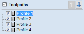
Tick each toolpath to ensure it is drawn / visible in the 3D window as shown:
Click on the Save option and the Save Toolpaths form is displayed. Select the option Output all visible toolpaths to one file
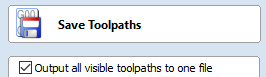
The names of the toolpaths that will be written into the file are displayed along with the tool number in square brackets [1]. If a calculated toolpath is not required, simply tick to undraw it.
Click the button Enter a suitable Name and click the button
Error Messages
The postprocessor automatically checks to ensure:
- It has been configured for saving files that include ATC commands
- A different tool number has been defined for each different cutter being used.
An error message will be displayed to indicate the problem if either of these items is not correct.
The Toolpath List
The Toolpath List is located at the bottom of the Toolpath Tab (toggle tab visibility using Shortcut key F12).
This area displays in a list, the name of each calculated toolpath with a check-box to turn the visibility of the toolpath in the 3D View on and off. The icon next to the check-box shows the type of tool selected for that particular toolpath.
Double clicking the name of any of the toolpaths will open up the toolpath strategy window for that toolpath and allow edits to be made to it.
The up and down arrow icons to the right of the window allow the user to move a toolpath up and down in the list. This will affect the order the Toolpaths are previewed in and if multiple toolpaths are saved as a single file, then this will be the order that the machine cuts them in.
You can adjust the space available for the Toolpath list by clicking and dragging the divider that separates the Toolpath List from the Toolpath Operations section, up or down.
Resizing the Toolpath List
The toolpath list can be resized by clicking on the divider between the toolpath list and toolpath commands area and dragging.
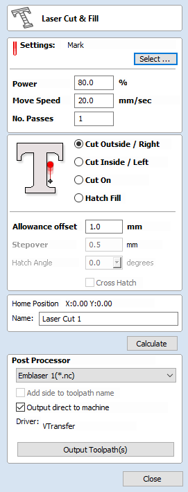
Laser Cut - Fill
Laser Cut - Fill is used for cutting out shapes or marking areas.
Cut-outs can take into account the kerf, or width, of the laser beam to maintain the precise internal or external size the selected vector shapes. Shapes can also be filled with stripes or hatching to create simple shading effects.
The fields on the form are as follows.
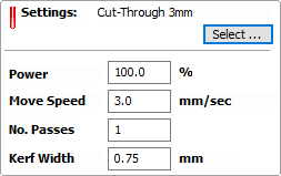
Settings
Select
This button opens your database of previously stored laser settings for different jobs and materials. When a setting is selected fromt the database it will be used to populate the key fields in this section. You can subsequenlty modify these values when calculating the laser toolpath. Modifying the settings on this form will not alter the original stored settings within your database.
Power
This value sets what proportion of your machines maximum laser power will be used for this toolpath.
Move Speed
This specifies the maximum speed that your machine will move during cutting or engraving moves. The units are determined by the database setting that was originally selected.
No. Passes
The machine can repeat a toolpath a number of times to cut through thicker material. This value sets the number of repeats.
Strategy
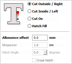
Based on the selected vector shapes in your drawing, this toolpath offers four distinct strategies
- Cut Outside / Right - Selecting this option will run the laser around the outside of your selected vector shapes (or along their right-hand edge, if they are open vectors). The actual path of the laser is automatically offset from the orginal shape according to the kerf width of the laser. As a result, the external dimensions of the resulting physical part precisely match the size of the original vector drawing. This strategy should be used for cutting out shapes to precisely the correct dimensions.
- Cut Inside / Left - This option will run the laser around the inside (or left-hand edge) of your selected vector shapes, allowing for the kerf of the laser. This strategy is typically used for cutting holes, slots or sockets where the remaining recess has precisely the same dimensions as the original selected vector drawing.
- Cut On - This option will runs the center of the laser beam along the selected vector. No offsetting or kerf compensation is required.
- Hatch Fill - This is a marking or 'shading' strategy which profiles along the selected vectors and then fills-in the shapes with stripes. When this option is selected the additional Stepover, Hatch Angle and Cross Hatch options will also become enabled - see below for more information on these.
Allowance
This setting allows you to add an additional offset for the Cut Outside, Cut Inside strategies without adjusting the laser kerf settings and can be useful for easing or tightening the fit of shapes resulting from these cuts.
Stepover
When creating hatch fills, this option determines the spacing between the hatch lines. It is only available when the Hatch Fill strategy is selected.
Hatch Angle
When the Hatch Fill strategy is selected, this option determines the angle of the hatching lines used.
Cross Hatch
Checking this option will create a cross hatch fill instead of a single set of lines.
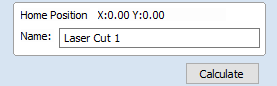
Toolpath Calculate
Home Position
These coordinates indicate the home coordinate position from which this toolpath will start and finish.
Name
Enter a meaningful name for the toolpath here. It will be stored in the toolpath list using this name.
Calculate
Clicking this button will initiate the process of calculating the toolpath using the form settings and adding the resulting toolpath to the toolpath list.
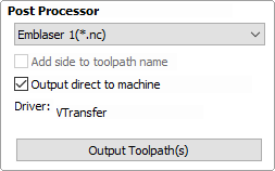
Immediate Output
Once calculated, your toolpath is stored in the central Toolpath List and can be saved, edited or output to your laser machine at anytime using the Save Toolpaths command. In addition though, this form also includes a convenient Immediate Output section that allows you to save or send the most recently calculated toolpath directly from this form without having to close it (see VTransfer for more information).
Post Processor
Use this drop-down list to select the post-processor for your machine.
Add side to toolpath name
If you are creating aligned toolpaths for a two-sided part, this option automatically adds the side name to the toolpath name as it is saved or exported to help keep your toolpaths organised.
Output direct to machine
If your post-processor supports direct access to your cnc machine (including machines supported by VTransfer), this option will be available. Selecting this option will bypass saving the toolpath to disk and instead send it straight to the direct output driver.
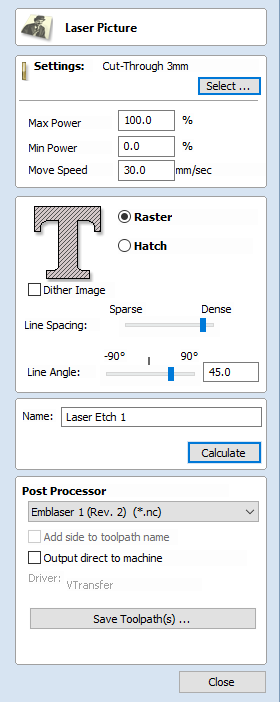
Laser Picture
The Laser Picture toolpath uses the laser to etch a copy of the selected bitmap picture into the surface of your material.
Preparing the bitmap
This strategy requires a source bitmap image or photograph to be selected in the 2D View. It will be converted into a laser toolpath by creating a dense stripe, or hatch, pattern over the image and then adjusting the power of the laser as it moves across the image to reproduce it using lighter and darker marks. The precise tonal range and contrast of the final part will be the result of an interaction between the original colors or shades in the bitmap, the way in which the material burns as well as the power and speed of the laser. For these reasons some experimentation may be required to find the best settings for a particular job.
Your source bitmap can be edited in a number of ways before using this form to create your laser toolpath. You can use the Crop Bitmap command to trim a bitmap to a vector outline. This will allow you to remove any parts of a bitmap that you do not require.
The Picture Edit tool can also be used prior to creating the toolpath in order to adjust many important aspects of your image - such as brightness and contrast. In addition it can be used to add a feathered border the image. For the best results you should use this tool to highlight and eccentuate out the important details of your image before creating your toolpath.
The fields on the form are as follows.
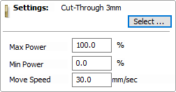
Settings
This section details the laser settings for this toolpath. The button will open the laser tool database where you can retrieve previously stored settings for a particular job or material. For convenience, these settings can also be modified in-situ on this toolpath form. Any edits you make directly on the form will only effect the current toolpath - they will not effect the stored settings in the database.
Max Power
This specifies the maximum power (as a percentage of the laser's maximum full power) that will be used for the darkest areas of the image.
Min Power
This specifies the minimum power (as a percentage of the laser's maximum full power) that will be used for the lightest areas of the image.
Move Speed
This setting allows you to locally override the move speed (or feed rate) of the cutting moves of your laser. For a fixed power the slower the laser moves, the darker the mark it will make. If you are already using maximum power but the image to still too light you may wish to slow the movement of the machine and burn for longer.
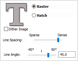
Strategy Settings
Raster
Selecting this option will generate a single set of parallel lines, or stripes, across your selected image.
Hatch
This option will create two sets of parallel lines at 90 degrees from one another. This strategy will generally produce a denser image reproduction, but will typcially take twice as long to etch.
Dither Image
With this option un-checked, laser power will be changed evenly in response to the lighter and darker areas of your image. Thus your image is reproduced by a range of burnt tones onto the surface of your material using continuously varying laser power. For some materials, however, the burning process tends to produce only two tones - burnt or unburnt - rendering this graduated approach ineffective. For materials with this property an alternative strategy can be used to generate the tonal range using only black dot patterns of differing densities instead - much like old newspaper picture print. This process is called dithering and it can be enabled using this option. In general you should only use this option if the material properties prevent you from using the higher quality true grayscale method.
Line Spacing
This slider adjusts the gap between the raster stripes - tight striping produces a denser image reproduction, but will take a lot longer to etch. The maximum density is set by the Kerf of your laser beam and the most sparse setting is 30 times this value.
Line Angle
Adjust this slider to change the angle of the stripes or hatching used to etch the image. Zero degrees will produce horizontal stripes and ninety degrees, vertical.
Toolpath Name
Name
Enter a meaningful name here before calculating the toolpath - this is the name under which your toolpath will appear in the toolpath list.
Calculate
Clicking this button will initiate the process of calculating the toolpath using the form settings and adding the resulting toolpath to the toolpath list.
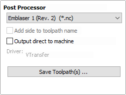
Immediate Output
Once calculated, your toolpath is stored in the central Toolpath List and can be saved, edited or output to your laser machine at anytime using the Save Toolpaths command. In addition though, this form also includes a convenient Immediate Output section that allows you to save or send the most recently calculated toolpath directly from this form without having to close it (see VTransfer for more information).
Post Processor
Use this drop-down list to select the post-processor for your machine.
Add side to toolpath name
If you are creating aligned toolpaths for a two-sided part, this option automatically adds the side name to the toolpath name as it is saved or exported to help keep your toolpaths organised.
Output direct to machine
If your post-processor supports direct access to your cnc machine (including machines supported by VTransfer), this option will be available. Selecting this option will bypass saving the toolpath to disk and instead send it straight to the direct output driver.
VTransfer
VTransfer is a small helper application provided by Vectric to simplify the process of sending toolpaths to some grbl-based controllers. You should run VTransfer on the PC to which your CNC machine is connected via a USB serial connection. If your Vectric CADCAM software is also running on the same PC, you can use Direct Output mode to send toolpaths to VTransfer directly, without the need for file saving or loading.
As well as streaming toolpaths, also VTransfer provides the commands you need to initiate basic homing, jogging and setting of origins on your CNC machine before a toolpath is run.
Getting Started
Before starting VTransfer, you need to ensure that your machine is powered on, any required drivers are already installed and the machine is accessible via a serial port (COM port on Windows). For most machines connected by USB, you will need to have installed the appropriate device driver for your machine controller. These drivers will be provided by your machine tool supplier and you should verify that your CNC machine connects correctly to your PC before attempting to use VTransfer.
When the machine and drivers have been installed correctly, refreshing and checking the drop-down Connect On: list will show your machine tool controller. VTransfer will still need to know the specific communication protocol required though and the first time you use VTransfer you will need to complete some one-time set-up and configuration.
Once set-up for a machine that remains connected to the same USB port of your PC, VTransfer should automatically detect and connect each time it starts-up. However you will need toInitial Set-up
Once this initial set-up has been completed VTransfer should automatically detect and connect to your machine on start-up, provided the machine remains connected to the same USB port of your PC. Before connecting to your machine for the first time, however, you should complete the following steps to set the right controller type and maching configuration.
- Select File->Settings from the main menu to open the Settings dialog
- Make sure that your controller is selected in the Controller Name: drop down list (for a grbl version 1.x controller this will be Grbl, for example)
- Select the correct configuration file for you machine, or create your own.
Controller Connection
- Make sure that your machine is connected to the PC via USB and it is powered on
- Click the button regenerate the Connect On: drop down list with all of the detected devices connected to your PC
- Select your controller device from the list - note that this may be the name of the microcontroller on which your controller is running, rather than the controller name itself (grbl may appear as Arduino UNO, for example)
- Check that the Machine Status reported by VTransfer reads Looking for... followed by the expected controller name
- Machine Status will change to Connecting while VTransfer attempts to verify the controller is communicating as expected
- Once correct communication has been established the Machine Status will change to Initialising, Alarm or Ready depending on how your machine is configured
Running a toolpath
Once connected to your CNC machine, the typical steps for running your first toolpath using VTransfer are:
- Open the Jog Tab
- If your Machine Status or unlock your machine (if supported and configured)
- Load your toolpath file or send one to VTransfer via Direct Output
- If required, jog the machine to the location of the material on your CNC machine (to match the relative origin point of your toolpath) and set the
- Fit the required tool
- Either run the Z Touch Plate cycle (if supported) to set Z Zero to match your toolpath
- Or manually jog the tip of the tool to the material surface or machine bed (again to match the Z Zero setting of your toolpath) and set the
- Ensure the spindle is on (if it is not controlled automatically)
- Open the Cut Tab - Click
Sending a toolpath directly to VTransfer from your Vectric software
At the point of saving your toolpath some post-processors support the option of Direct Output to VTransfer (such as the Emblaser or X-Carve). If you have one of these post-processors selected, the Output direct to machine checkbox will be enabled below the post-processor selection box. With this box checked, will change to and clicking this button will automatically send the toolpath to VTransfer. If VTransfer is not already running, it will launch automatically.
Whenever a new toolpath is loaded or received by VTransfer it will prompt you with a message box.
Homing, Jogging and Origins
Before running your toolpath it is essential to set your machine's origins appropriately. The specific process you need to use will, to a large extent, will be determined by your machine and its configuration. Generally you will need to home your machine (if supported) and set the X Y origin to match the intendended toolpath and location of the material on your machine's bed. You will also need to fit the correct tool and typically set the tip of this tool to be at Z Zero, either at the top or bottom of your material - again this choice will already have been determined when your toolpath was created. The commands relating to these actions are all available from the Jog tab.
Whenever VTransfer changes its origin settings you will be prompted with a message box.
Start Homing Sequence
Click this button to initiate the homing sequence. The homing sequence will culminate in setting the origins of your machine using its homing switch locations and the machine's machineable area - both of which are set in the configuration. For some controllers (such as grbl) you will typically be required to run this command before you can do anything else because the machine will start-up in a disabled Alarm status.
Z Touch Plate
This button will be visible if your machine is configured with a touch plate, touch plate support is enabled and its thickness is set in the configuration settings. Click it to initiate the Z touch plate probing cycle. Make sure that the touch plate is in position and correctly functioning before clicking this option as it will immediate begin a plunge move.
Jogging
The , , , , and buttons will each jog the machine along the Y, X or Z axes, respectively.
The distance moved by each button click is determined by the current value (in mms) shown in the drown-down control at the center of the jogging buttons. Ensure that you adjust this value appropriately before using the jog buttons to move the machine.
Setting and Resetting Origins
By default a machine with homing support will have its X Y origin (the postion of the coordinate X:0 and Y:0) set to the bottom left corner of machine's machinable area following a homing cycle - i.e. the machine will operate in a positive coordinate work space within its machinable area. For machines without homing support, the initial X Y origin must always be set manually before running a toolpath. In additon, when a toolpath is created it is very common that the X Y origin will actually be chosen to be relative to the material (not the machine bed) - for example, the center of a design may be used. For most toolpaths, therefore, you will need to jog the machine to the matching origin location for the toolpath (relative to your material), and manually before cutting.
For machines with homing support, you can restore the bottom left corner origin after setting it for a specific toolpath by clicking at any time. When this button is clicked the location of coordinate position X:0, Y:0 will once again be set to the bottom left corner of the machine's machinable area.
Running the Toolpath
The Cut tab contains the controls need to begin cutting your toolpath and monitoring its progress.
Cut Now
When your machine is correctly set-up (with the X,Y and Z origins set), click this button to begin streaming the toolpath to your machine and begin cutting.
Estimated Time Remaining
Once your toolpath has started, VTransfer will provide a dynamic estimate of the remaining time until the toolpath is finished.
Dynamic Feedrate Override
If your machine supports feedrate override control and the option is enabled in your configuration, then the and buttons will be available. Click these buttons to increase or decrease the current toolpath feedrate by 10%. The current state of the feedrate override setting is indicated by the percentage value between the two control buttons.
Abort
This button will stop the toolpath as quickly as possible, usually resetting the controller in the process. Once a toolpath has been aborted you should re-home and re-origin before running a subsequent toolpath.
Settings
Main Menu
Clicking on any of the options on the title bar (File, Edit etc.) will result in a drop-down menu appearing with choices related to that topic.
Many of these are just an alternative way to access functions also accessed through the icons. However, there are a few commands that are unique to the Drop Down menu. Each menu and its contents are discussed later in this section of the manual.
Only unique items which do not have an equivalent icon that has already been discussed in the manual will be dealt with in detail.
| File | Edit | Toolpaths | View | Help |
File
|
New | Creates a New Cut2D Laser Desktop job. |
|
Open... | Opens an existing Cut2D Laser Desktop job |
| Close | Closes the current file but leaves the software running | |
|
Save |
Saves the current Cut2D Laser Desktop file over the last saved version of the file.
Note: This command will overwrite the old file with any changes made
since the last save. If you are not sure of your changes then use the File ⇒ Save As... command instead
option and give the file a new name.
|
| Save As... | Opens the standard File Save dialog so you can save the current file with a new name. | |
| Increment and Save |
The Increment and save operation allows you to automatically number iterations of files you are working on. If you select this operation when editing a file which ends with an underscore, or a hyphen followed by a number, then the number will be increased by 1 and the file will be saved using this number. For example, MyFile_1.crv3d becomes MyFIle_2.crv3d MyFile-1.crv3d becomes MyFile-2.crv3d
Note: The increment and save option will keep incrementing until
it finds a file that does not currently exist. It will not overwrite an existing file.
|
|
| Opens the Print Setup box to Print your design | ||
| Print Preview | Displays a Preview of the design to print | |
| Print Setup | Opens the Print Setup box to Print your design | |
| Import... ► | Import various entities into the job | |
| Export... ► | Export vectors from the job | |
| Open Application Data Folder... |
Opens the Windows folder where files used by the software are stored. This is useful for adding to the default files installed initially. Application files include: Bitmap textures for creating custom materials. Gadget scripts for customized automation of the software. Postprocessors The Tool Database Default toolpath strategy settings Vector texture files. |
|
| Exit | Closes the job and exits the software. |
Import
|
Import Vectors... | Import Vector data. |
|
Import Bitmaps... | Import Bitmap data |
 |
Import Component / 3D Model... | Import 3D Model or Component |
| Import PhotoVCarve or Cut3D Toolpaths... | Import a toolpath file created in another Vectric application, such as, Cut3D or PhotoVCarve. |
Export
|
EPS DXF AI SVG |
Allows you to export selected Vectors as either an eps, dxf, ai, svg or pdf format vector file. If no vectors are selected, the all visible vectors will be exported.
Note: When exporting in DXF format, the layer information relating to the exported vectors is preserved.
|
Printing and Print Preview
The contents of either the 2D or 3D view can be printed using the Print... command on the File menu. Simply select the view you wish to print (2D or 3D) and then click the Print... command. The standard Windows printer dialog allows you to select the printer and adjust its properties. When the OK button in this dialog is clicked, the view will be printed. To adjust the printer settings without printing, you can open the same dialog using the Print Setup... command on the File menu. When used in this way, the button on the dialog will store the settings without printing immediately.
The Print Preview... command on the File menu allows you to check the layout of your page before you print. If you are happy with the preview, use the button to begin printing the document directly from the Print Preview page.
Edit
|
Undo | Steps backwards through the last 5 changes made by the user. |
|
Redo | Steps forward through design steps that have been Undone using the Undo command (see above) to get back to stage that the user started using the Undo function. |
|
Cut | Removes the selected objects from the job and places them onto the clipboard. |
|
Copy | Copies selected objects to the clipboard, leaving the original in place |
|
Paste | Pastes the contents of the Clipboard into the model (see cut and copy above). |
| Delete | Deletes the selected object - same as hitting the delete key on your keyboard | |
| Selection ► | Select various types of vectors | |
| Align Selected Objects ► |
Give the user all the options covered under the Align Objects section of the menu. Opens the Alignment Tools form. |
|
| Join Vectors |
Joins open vectors. Opens the Join Vectors form. |
|
| Curve Fit Vectors |
Allows arcs, Bezier curves or lines to be fitted to existing vectors to 'smooth' them. Opens the Fit Curves to Vectors form. |
|
|
Job Size and Position | Opens the Job Setup form. |
| Notes |
Opens a text box where you can record notes regarding this job, such as customer name, material required, special setup instructions or any other relevant text information you would like to keep when you save the job. If the text starts with a period/full stop/dot '.' , the Notes dialog will be displayed automatically each time the file is opened. The text from the Notes dialog can also be optionally output into the toolpath as a comment field. See the Help Menu ► Post-Processor Editing Guide. |
|
| Document Variables | Opens the Document Variables dialog. | |
| Snap Options | Opens the Snap Options dialog. See Rulers, Guidelines and Snapping for more details. | |
| Options | Opens the Program Options dialog to allow the customization of certain aspects of the program. |
Selection
| Select All Vectors | Selects all the currently visible vectors in the part (vectors on invisible layers are not selected). | |
| Select All Open Vectors | Selects all the currently visible Open vectors in the part | |
| Select All Duplicate Vectors | Selects all the currently visible Duplicate vectors in the part - these are vectors which are exact copies of each other in terms of shape and location so that visually they appear to be only one vector. These can cause problems for some toolpath and modeling functions so it can be useful to delete them or move them to a new layer. | |
| Select All Vectors On Current Layer | Selects all the vectors on the selected layer. | |
| Unselect All | Deselects all the currently selected vectors in the part | |
| Vector Selector... | Opens the Vector Selector dialog. |
Toolpaths Menu
 Show Toolpaths Tab
Can be checked ✓ on or off to pin the Toolpath Tab open or unpin
Show Toolpaths Tab
Can be checked ✓ on or off to pin the Toolpath Tab open or unpin  and hide it.
Tool Database
Opens the Tool Database Dialog.
Recalculate All Toolpaths
Recalculates all the Toolpaths in the part.
Toolpath Drawing ► Opens the Toolpath Drawing Pop-up Menu.
Install Post Processor Opens a File Open dialogue box where you can install a post processor.
Toolpath Drawing sub-menu
View
Zoom to Drawing
Use when you need to see the whole drawing and material as large as will fit in the 2D View window.
F5 Refresh 2D View Shortcut key for this is F5. In situations where the complete vector geometry represents a very large job and the user zooms into a small region, the shape of arcs and curves may look faceted. This is only a display issue and will not impact on the quality of toolpaths. This command will rebuilds the display information to correct the graphics being drawn on the screen so curves are drawn smoothly again.
Guide Lines ► For more details see the section on Rulers, Guidelines and Snapping at the end of the 2D Design part of this manual. Opens the Guide Lines Pop-up Menu:
Delete All Guides: Deletes all the Guide Lines in the 2D view.
Lock All Existing Guides: Locks the position of all the Guide Lines in the 2D view.
Unlock All Existing Guides: Allows all the locked Guide Lines in the 2D view to be moved again.
Draw Material Block: Toggles the drawing of a wireframe representation of the limits of the material block. This is useful for seeing how the 3D model will be positioned in the block of material it is being cut from.
= Multi Sided View: Allows you to view both sides in the 2D and 3D view when working in a multi sided environment.
Help
Help Contents: Displays an online version of the full reference manual that documents every feature and option available in the software.
Keyboard Shorcuts: Displays the Shortcut Keys available in the software.
Video Tutorial Browser...: Access the tutorials
What's New: See a summary of the new features added in major updates.
Release Notes: See the list of issues fixed and enhancements in patch updates.
Enter License Code The license details provided when you purchase Cut2D Laser Desktop
View the Vectric User Forum...: Opens the Vectric User Forum in your Web Browser if you have an Internet Connection. Everyone should join the Forum to engage with other users and benefit from each others tricks and tips!
Visit Vectric Support online...: Opens the Vectric Support Website in your Web Browser if you have an Internet Connection.
Visit Vectric User Portal...: Opens theVectric User Portal in your Web Browser if you have an Internet Connection. Download software installation files, activation codes and Clip Art included with the software.
Post Processor Editing Guide: Opens a PDF manual explaining how to create and edit your own post processors.
Migrate From Older Version
Opens a dialog to enable the settings in the last version of Cut2D Laser Desktop to be copied to the latest version:
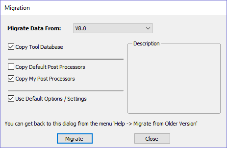
Check for Updates Try this periodically to check (through the Internet) if an update is available for your software.
About Cut2D Laser Desktop... This window displays the version of the software being used, to whom the software is license and the type of license.
Right Mouse Click menus
Clicking the ►RIGHT hand mouse button in different places in Cut2D Laser Desktop will display a menu with choices which depend on the area of the software being clicked on and/or the object or selection that the mouse cursor is positioned over. This document details some of these areas and the menus that you will see when RIGHT mouse clicking.
2D View Right Mouse Menu
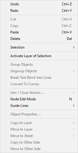
This menu is displayed when you Right mouse click in 2D View either in the white background of the part or over a selected vector. Most of these options repeat functions and icons described elsewhere in this manual, you should refer to the appropriate section to view how these work.
The Copy to Layer, Move to Layer and Move to Sheet options are unique to this Right click menu. Copy to Layer allows you to copy an object onto an existing Layer or to create a New one to copy it onto. Move to Layer gives you the same choices but moves the original object rather than making a copy. Move to Sheet can only be used if you have generated additional Sheets through the Nesting process, in that case it allows you to move objects from one Sheet to a different one from the list available.
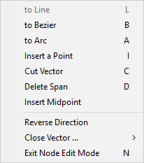
Span Editing Menu
If the currently selection mode is set to Node Editing, one of 2 different menus will appear when the user clicks the RIGHT mouse button depending on whether the cursor is currently over a vector Node or a Span in the selected vector in the 2D View. These menus have functions in them that correspond specifically to this selection and position. The menu below will appear when the cursor is over the Span of a vector in Node editing mode. You can see a variety of choices: to convert the span to a Line, Bezier (curve) or Arc, Insert a Point, Cut the Vector at that point, Delete the Span, or Insert a Midpoint. All these have corresponding Short Cut keys (shown to the right of the command in the menu) which can be selected from the key-board when the mouse is in position (over a node-edit vector span) instead of Right Clicking the mouse button to access the menu.
Node Editing Menu
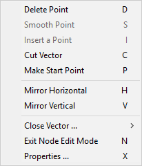
This menu will appear when the cursor is over the Node of a vector in Node editing mode. You can see a variety of choices to convert the span to Delete the Point, Smooth it, Cut the vector at that point or change the point to be the Start Point on the vector. From this menu you can also close the vector, Exit the node editing mode and lastly see and edit the exact XY co-ordinate position of the node by selecting Properties. All these have corresponding Shortcut keys (shown to the right of the command in the menu) which can be selected from the key-board when the mouse is in position (over a node-edit vector node) instead of Right Clicking the mouse button to access the menu.
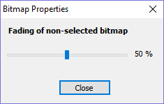
Bitmap Properties Dialog
When a Bitmap or Component Grayscale is the selected item in the 2D View and the RIGHT Mouse menu is activated then there will be an additional option in the pop-up menu called Object Properties. This will open the dialog shown below which can be used to fade the Bitmap or Grayscale object strengthen or fade the detail in it when it is not selected. This can be helpful to make it easier to see features perhaps to help you manually trace vectors over it or to fade them so its easier to see vectors that overlap the object.
Toolpath List Menu
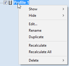
When you RIGHT click on a toolpath name within the Toolpath List there are various options you are presented with to alter this toolpath. You can show a toolpath where you have the option to Show This, Show Only This, Show All But This and Show All. This toggles the visibility of the Toolpaths according to your choice. The next option allows you to Hide This or Hide All your toolpaths. You can Edit, Rename or Duplicate the selected toolpath. Selecting Recalculate All will work through the toolpath list recalculating each toolpath with any updated geometry selections. The last option allows you to delete one or more toolpaths, where you can Delete This, Delete All Invisible, Delete All Visible and Delete All.
Glossary
2D View
Shows the workspace defined when you create a new file. This is used to control the XY layout of vectors and bitmaps. Typically you select an item from this view by clicking on it or dragging a box around it with the mouse. To move it you can click a selected item a second time to go into Transform mode. Some items when double clicked will open a form relating to the object and many have functions related to them displayed when you right mouse click over them.
Group
When you want to manipulate a number of objects together you can Group them. This is a temporary operation to ease the selection, movement, scaling, and rotation etc. of several objects at once. It is reversed by Ungrouping.
Ungroup
Separates a set of Grouped Objects so that they can be manipulated independently again.
File
Generic name most often used to describe a complete Cut2D Laser Desktop project (CRV file) which contains all the 2D and Toolpath information in a single saved file - also sometimes referred to as a Part.
Short Cut Keys
Keys on the keyboard which will activate certain commands when pushed. Example F4 to activate the Snapping Options Dialog. You can find a full list of all the Shortcut Keys in the online reference manual in the Frequently Asked Questions section.
Vector
A 2D object represented by lines, arcs or curves.
Shortcut Keys
| On this page: | Quick Keys: |
General Shortcut Keys
| Shortcut key | Description |
|---|---|
| Ctrl + A | Select All vectors |
| Esc | Deselect All vectors |
| Select ⇐ Right to Left |
Selects all vectors inside and touching selection rectangle |
| ► Select Left to Right |
Only selects vectors fully inside selection rectangle |
| N | Toggles between Selection and Node Editing modes |
| Esc | Switches to Selection Mode (exits Node editing or Transform mode) |
| T | Opens the Scale form for Transforming the vectors |
| M | Opens the Move form |
| R | Opens the Rotate form |
| J | Opens the Join Vectors form |
| Ctrl + M | Opens Measure tool form |
| 9 | Rotates selected object 45° counterclockwise |
| 0 | Rotates selected object 45° clockwise |
| Esc | Exits vector drawing and editing tools and closes the data entry form |
| Right mouse click |
Exits vector drawing and editing tools and closes the data entry form |
| Space-bar | Re-opens the last vector creation form you used. This is very useful when using other forms in between each shape / text / dimension you create. |
| Z | Zoom - click top left and bottom right corners to zoom |
| Esc | Exits zoom mode returning to Selection mode |
| CRTL + F | Zoom to fit Job |
| F | Zoom to fit Material |
| F6 | Zoom to fit Material |
| F1 | Opens the Help File |
| F2 | Opens the 2D Drawing window |
| F3 | Opens the 3D Preview window |
| F4 | Opens the Snap Settings form |
| F5 | Refreshes the 2D window |
| F6 | Scales 2D view to fit material |
| F9 | Center selected object in view |
| F10 | Opens the Alignment Tools form |
| F11 | Toggle Drawing Tab on |
Tab Navigation
| Shortcut key | Description |
|---|---|
| F11 | Toggle Drawing Tab on |
| Ctrl + L | Opens the Layers Tab |
| Ctrl + D | Opens the Drawing Tab |
Double Sided Job Setup
| Shortcut key | Description |
|---|---|
| 1 | Toggle Top Side on |
| 2 | Toggle Bottom Side on |
| = | Toggle Multi-Sided View on |
Mirror
| Shortcut key | Description |
|---|---|
| H | Mirror Horizontally |
| Ctrl + H | Create Mirror Copy Horizontally |
| Shift + H | Mirror Horizontally, around center of material |
| Ctrl + Shift + H | Create Mirror Copy Horizontally, around center of material |
| V | Mirror Vertically |
| Ctrl + V | Create Mirror Copy Vertically |
| Shift + V | Mirror Vertically, around center of material |
| Ctrl + Shift + V | Create Mirror Copy Vertically, around center of material |
Alignment
| Shortcut key | Description |
|---|---|
| F9 | Moves selected object to the center of the material |
| F10 | Opens the Alignment Tools form |
Groups
| Shortcut key | Description |
|---|---|
| G | Group: Creates a single group containing selected vectors / components |
| U | Ungroup: Converts a Group to individual vectors or components |
| Ctrl + U | 'Deep' ungroup the selected objects to their original layers.Sub-groups are also ungrouped |
| Ctrl + Shift + U | 'Deep' ungroup the selected objects to their groups layers. Sub-groups are also ungrouped |
Arrow keys
Nudge selected vectors using the Arrow keys
- Holding Ctrl reduces the nudge distance
- Holding Shift increases the nudge distance
- Holding Ctrl + Shift nudges the selected object by the Fixed Nudge Distance which is specified in the Snap Settings (F4)
Node Editing
| Shortcut key | Description |
|---|---|
| I | Insert a Point |
| D | Delete Point / Span |
| S | Smooth / Unsmooth Point |
| C | Cut Vector opens the vector |
| B | Convert span to Bezier |
| A | Convert span to Arc |
| L | Convert span to Line |
| P | Makes the selected node the Start Point for machining |
| X | Displays a single node's X and Y location properties |
| X | Changes the X co-ordinate position of selected nodes to match the position of the first one (when more than one selected) |
| Y | Changes the Y co-ordinate position of selected nodes to match the position of the first one (when more than one selected) |
| H | Enter horizontal mirror mode (press again to exit) |
| V | Enter vertical mirror mode (press again to exit) |
| Right mouse click |
Opens context sensitive menus |
| Ctrl + Z | Edit Undo |
| Ctrl + Y | Edit Redo |
| Ctrl + C | Copy the selected vectors |
| Ctrl + V | Paste the selected vectors |
| Ctrl and Drag | Pastes a copy of the selected vectors each time the left mouse button is released. |
| Ctrl + X | Cut the selected vectors |
| Alt and Drag | Moves the object either horizontally or vertically aligned with its original position |
| Ctrl + Alt and Drag | Creates a copy of the original object horizontally or vertically aligned to its original position |
| Ctrl + N | Create New file |
| Ctrl + O | Open an Existing file |
| Ctrl + S | Save file |
| Ctrl + I | Import file |
| Page Up |
Vertically tiles the 2D View and the 3D View window so you can see them both simultaneously. Currently Selected window is on the left - typically best to select the 2D View first when doing this. |
| Page Down |
Horizontally tiles the 2D View and the 3D View window so you can see them both simultaneously. Currently Selected window is at the top - typically best to select the 2D View first when doing this. |
Quick Keys
Pressing the Space-bar re-opens the last vector creation form you used. This is very useful when using other forms in between each shape / text / dimension you create.
Various values can be typed in while dragging out shapes as follows:
Note: In most cases, the left mouse button must be pressed in order to input a value (i.e.dragging to create a circle, dragging a vector to move it, or dragging one of the rotating/scaling points around a vector to rotate/scale it).
The exception to this is the polyline tool: once the first point is entered the Quick Keys can be used without having to depress the left mouse key. Entering values defines the next end-point.
Moving Objects M
| Drag Object | Description |
|---|---|
| ValueEnter |
Moves object the L Value from original position in direction of cursor. Equivalent to:ValueL. |
| Value,ValueEnter |
Moves object relative to its position by X and Y. Equivalent to:ValueDValueW. |
| ValueXValueY | Moves object to the absolute position X and Y |
Rotating Objects R
| Drag Rotation Handles | Description |
|---|---|
| ValueEnter |
Rotate the selection by R degrees counterclockwise. Equivalent to:ValueL. |
Scaling Objects T
| Drag Scaling Handles | Description |
|---|---|
| ValueEnter |
Default when dragging edge scale nodes only. Set the width or height of the object to 'L' (depending on which handle is being dragged). Equivalent to:ValueL. |
| Value,ValueEnter |
Default when dragging corner scale nodes only. Set the width and height of the object to the given values. Equivalent to:ValueDValueW. |
| ValueS | Scale the object by a factor. |
Node Editing N
| Drag Node | Description |
|---|---|
| ValueEnter |
Moves node from original position by that amount in direction of cursor. Equivalent to:ValueL. |
| Value,ValueEnter |
Move the node by that amount relative to its current position. Equivalent to:ValueDValueW. |
| ValueXValueY | Moves node to the absolute position X and Y |
Polyline Tool
| Value after adding first point | Description |
|---|---|
| ValueEnter |
Places next point L away from the last point in the direction of cursor. Equivalent to:ValueL. |
| Value,ValueEnter |
Place the next point offset by that amount relative to the last point's position. Equivalent to:ValueDValueW. |
| ValueXValueY | Places the next point at position X and Y |
| ValueAValueL | Creates a line with an angle of A° and a length L |
Draw Circle
| Value(s) while Dragging Mouse | Description |
|---|---|
| ValueEnter |
Create a circle with the given radius. Equivalent to:ValueR. |
| ValueD | Create a circle of Diameter D |
Draw Ellipse
| Value(s) while Dragging Mouse | Description |
|---|---|
| ValueEnter |
Create a circle with the given diameter. Equivalent to:ValueL. |
| Value,ValueEnter |
Create an ellipse with width and height. Equivalent to:ValueWValueH. |
| ValueX | Create an ellipse with width X and use the current height |
| ValueY | Create an ellipse with height Y and use the current height |
Draw Rectangle
| Value(s) while Dragging Mouse | Description |
|---|---|
| ValueEnter |
Create a sqaure with the given side length. Equivalent to:ValueL. |
| Value,ValueEnter |
Create a rectangle with given width and height. Equivalent to:ValueWValueH. |
| ValueX | Create a rectangle with width X and use the current height |
| ValueY | Create a rectangle with height Y and use the current height |
| ValueRValueX | Create a rectangle with a radius R and width X, using current height |
| ValueRValueY | Create a rectangle with a radius R and height Y, using current width |
| ValueWValueH | Create a rectangle with width W and height H |
| Value,ValueEnter | Create a rectangle with width and height |
Draw Polygon
| Value(s) while Creating Mouse | Description |
|---|---|
| ValueEnter |
Create a circle with the given radius. Equivalent to:ValueR. |
| ValueD | Creates a Polygon with diameter D |
| ValueSValueR | Create a polygon with number of sides S and radius R |
| ValueSValueD | Create a polygon with number of sides S and diameter D |
Draw Star
| Value(s) while Dragging Mouse | Description |
|---|---|
| ValueEnter |
Create a star with the given radius. Equivalent to:ValueR. |
| ValueD | Create a star with diameter D |
| ValuePValueR | Create a star with number of points P and radius R |
| ValuePValueD | Create a star with number of points P and diameter D |
| ValuePValueIValueR | Create a star with number of points P , Internal Radius % I and radius R |
| ValuePValueIValueD | Create a star with number of points P , Internal Radius % I and diameter D |
What's New in Cut2D Laser Desktop V9.0
Welcome to Cut2D Laser Desktop V9.0!
This documentation provides a convenient guide for previous Cut2D Laser Desktop customers to highlight new and enhanced features specific to this release of the software. It is intended as a way for existing Cut2D Laser Desktop users to locate just the new or changed aspects of the software.
If you are new to Cut2D Laser Desktop, don't forget that full documentation of all the features of the software can be found here, or by selecting Help ► Help Contents from the Main Menu on Cut2D Laser Desktop's main window.
New Drawing Tools
This latest version of Cut2D Laser Desktop introduces several entirely new drawing tools and features,
Smart Snapping
The way you draw in the software has seen some huge improvements making it quicker and easier to create and align geometry in the software with the introduction of Smart Snapping. Smart Snapping can dramatically reduce the time taken to create vector geometry. It enables geometry to be snapped to lines, extensions and intersections which don't exist as geometry thereby reducing the need for most construction vectors.
Quick Keys
In addition to the Smart Snapping feature we have introduced the ability to transform and create shapes using Quick Keys. This allows you to add more precision to your shape creation and editing process more easily by allowing typed values while creating geometry. This is supported for creation of circles, ellipses, rectangles, polygons, stars, polylines and in editing nodes or transforming vectors.
Pressing the Space-bar re-opens the last vector creation form you used. This is very useful when using other forms in between each shape / text / dimension you create.
Vector Validator
The Vector Validator is intended to help locate issues with contours after importing vector files to look for problematic issues that could potentially affect toolpath creation such as overlapping contours or intersections. It also indicates zero-length spans that are in the file, where the software can fix them at the click of a button.
Enhanced & Extended Drawing Tools
This section details the improvements that have been made to features you will already be familiar with from earlier versions of Cut2D Laser Desktop and includes the following:
- Dimensioning
- All Closed Shape creation tools are now fully consistent
- Create tangents lines to circles & arcs using the Polyline Tool
Dimensioning
Further improvements have been made to the way you can create dimensions in the software. It has been enhanced to allow faster placement and more freedom. You now have the option to edit existing dimensions while the form is open. Dimensions can now have custom text. This text is stored per dimension, so you change between calculated and custom text without losing a dimension's custom text.
Shape Creation
Improvements have been made to the way we create shapes. If a shape is selected when a shape's form is opened, the form will load its values from the selected shape, otherwise it holds the same values it had when it was last closed.
When drawing a shape, the size of the shape you are drawing will be displayed, changing appropriately for the snap radius and job size. You can now edit a shape whilst in the shape form.
Creating Tangent Lines
Using the keyboard shortcut T in the Polyline Tool, you can create a tangent to and from existing arc spans or circles.
General Improvements
Two-Sided Job Support
Major changes have been made throughout the software to support jobs which require you to machine both sides of your material. Cut2D Laser Desktop now helps you to manage and organize your drawings, models and toolpaths for each side of your part using simple controls. The software helps with correct alignment of your vectors and toolpaths and even provides a full 3D preview of your part as it will look when cut from both sides. For lots more information please see the new Two-Sided Machining section of the full documentation.
View Toolbar
A new View Toolbar is displayed above the view window, which allows easier access to common tools. With the ability to create a double sided project you have easy access to switch between the Top and Bottom Sides of your project. The Layers Drop down bar has now moved from the drawing tab to the View Toolbar, making it accessible at all times. The other icons displayed in order of left to right are as follows:
Snapping Toggle Options
View Controls
- Toggle Pan / Twiddle View
- Zoom to box
- Zoom to drawing
- Zoom to selection
Toolpath Drawing Toggle
- Toggle 2D Toolpath Drawing
- Toggle solid 2D Toolpath Drawing
There are also additional tools available when you are working on a two-sided job. For more information, please see the Toolbar section of the documentation.
Export to PDF
You can now export your drawings to PDF. This is a useful and standard format but it also enables you to print your drawings to scale on a suitable printer using Adobe or other 3rd party PDF software.
Release Notes
Version 9.016
Features
- Added Laser Picture toolpath strategy
- Added image editing tool
- A new version of VTransfer.
Bug Fixes
- Fix preview artifacts in some cases on slower simulation speed.
- Fix toolpath-related crash when changing from single-sided to double-sided.
- Remove unintended 'customize' menu.
- Restore profile parameters when switching to create tabs.
Version 9.015
Bug Fixes
- Fix gouge in some join moves where the offset contours were extremely small.
- Display file names correctly in the title if they have a full stop in their name.
- Fix vector colours when exporting to DXF.
Version 9.014
Bug Fixes
- Fix intermittent random crash on startup when in non-english languages.
- Fix rare crash when exporting PDF.
Version 9.013
Bug Fixes
General & Drawing
- Fix filleting tolerancing issue in inch jobs.
- Fix a PDF export scaling issue where the size was off by a very tiny amount.
- Fix some document variables pasting the content of the copy/paste buffer.
- Fix linking X and Y sizes on the scaling form in some cases.
- Update the 2D view when importing a Machinist project.
- Ensure the 2D view is up-to-date when popping up the notes dialog on startup.
- Fix Job Setup form resetting the Z origin
Modeling
- Fix a case where the model was not placed within the material block correctly.
Toolpaths & Simulation
- Fix number of passing resetting on recalculating a profile toolpath when the cut depth is set to a variable.
- Fix applying a pocketing offset to some circles.
- Fix Moulding Toolpath corner rounding.
- Fix Array Copy Toolpath not optimising for tool changes correctly in some cases.
- Fix Array Copy Toolpath recalculate
Version 9.012
Bug Fixes
- Fix an issue with negative allowances on pocketing toolpaths.
Version 9.011
Bug Fixes
General & Drawing
- Fix issue with offsetting tool on heart-beat polylines.
- Fix number of pixels not matching resolution on the dropdown on the job creation form.
- Switching sides toolbar button works even when the toolbar is not displaying all the buttons.
- Fix filleting showing invalid cases as valid.
- Don't allow filleting in cases where the fillet ends are not tangent with the vectors.
- Don't move undone deleted vectors on the active sheet.
- Fix offsetting issue with heart-beat shape.
- Maintain the window layout (if the option is selected) even when openning directly through explorer.
Toolpaths & Simulation
- Ensure selected toolpath is scrolled to and visible in the list.
- Fix various issues in simulation colouring of machined area.
- Fix toolpath tooltip spindle speed units text.
- Make toolpath tooltip in the Summary form consistent with the toolpath list.
- Fix Profile Toolpath 'Start At' radio button behaviour when going into the Tabs form.
- Fix job offset controls in the Material Setup form to be more in line with the Job Setup form.
Enhancements
General & Drawing
- Allow creation of squares and circles from the rectangle and ellipse tools using a single Quick Key value.
- Support snapping to the job when measuring between two points.
- Improve speed of SketchUp file importing when we are not importing all layers.
Toolpaths
- Add option to allow appending duplicated toolpaths to the list (as opposed to adding under the original).
- Trigger project saving when exiting on toolpath renaming.
Version 9.010
Bug Fixes
General & Drawing
- Fix SVG importing of some horizontal and vertical lines.
- Fix vectors' visibility when reaching the maximum zoom level
- Ensure vectors and components move with the job when changing its center offset values
- Fix filleting when there are vectors on multiple sheets or opposite sides.
Toolpaths & Previews
- Fix pocket toolpath's slot machining ignoring other normal pockets
- Fix crash when changing the material thickness from the 'Material Setup' form
- Fix moulding toolpath crash when offsetting by tool radius
- Ensure fluting toolpaths reach the full depth specified on extremely shallow depths
- Fix merge toolpath ordering issue when 'Merge by Part' option is used
- Fix crash when merging toolpaths with the 'Dragknife' gadget
- Fix simulation global fill colouring of toolpath machined areas.
Enhancements
Drawing
- Allow snapping the mouse position as usual when moving vectors.
- Add option to PDF exporting to allow excluding the job material boundary.
Version 9.009
Bug Fixes
General & Drawing
- Clicking off the layer list (from the View Toolbar) doesn't lose the focus to other applications (Windows 10 issue).
- Fix potential rare crash in Job Setup form.
- Hide splash screen if a note is to be displayed on startup of a project.
Toolpaths & Previews
- Ensure the toolpath preview colour changes immediately when chaging through the preview form.
- Respect various toolpath drawing options when drawing tiled toolpaths.
- Re-instate stand-alone toolpath list, previously available in 8.5. This is accessible by double clicking the toolpath list title ('Toolpaths' or 'Toolpaths (Top)')
- Fix toolpath 'Show' & 'Hide' option on the right-click mouse menu.
- Fix reduced resolution for some Finishing toolpaths
- Fix moulding toolpath incorrect variable geometry with certain profiles.
Enhancements
General
- Prompt users that an update was successful, and option to view its release notes.
Version 9.008
Bug Fixes
Drawing
- Don't delete existing Guides when importing a crv file.
- Measure tool now maintains its last state correctly.
Toolpaths & Preview
- Fixed 2D Solid preview for VCarve toolpaths.
- Read Pocketing and Quick Engraving last pass option from older projects.
- Maintain simulation options to animate view and draw tool.