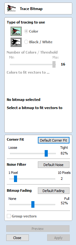
Trace Bitmap

This tool automatically traces or fits vectors to image files so they can be machined. Use the Import Bitmap tool and select the image in the 2D view, then open Fit Vectors to Bitmap.
After importing an image the Tracing option allows vector boundaries to be created automatically around colored or black and white regions in the image.
Tracing a Selected Area of the Bitmap
You can define an area within the bitmap, such that only that part of the bitmap will be traced. This can be done by selecting the bitmap (if this hasn't been done already), and then clicking and dragging the mouse over the area you want, to define a rectangular region on the bitmap. This will be highlighted with a dashed black rectangle.
Clicking on the Bitmap again will remove a selected area if one has been specified, in which case, the entire bitmap will have vectors fitted to it.
Images can be traced either in color or black and white mode and the basic process is described below:
If the image is black and white already, the process can be considerably simplified by selecting the Black/White option.
For color images you can also reduce the number of colors you need to work with by using the slider to further simplify the trace selection process.
Check ✓ the boxes next to each color swatch to link colors to the Trace Color. These are the colors that will be included in the area to trace.
Adjust the fitting parameters for the resulting vector and use the button to trace.
Click the button when you are happy with the preview.
After vector fitting you will often need to adjust the vectors so be sure to watch the video tutorials on vector editing available for the software.
Working with Color Images
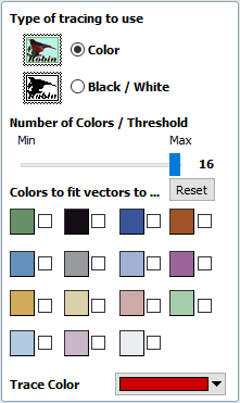
Color images are automatically reduced to 16 colors and the slider allows the visible number of colors to be set as required. Colors are merged with the closest match.
Colors can be temporarily linked together by clicking the check boxes next to each of the colors displayed. This changes the color displayed in the 2D view to the selected Trace Color. This is very useful for merging similar color's together to allow complete regions to be traced.
If a new Trace Color is selected the linked colors are displayed using this color in the 2D view.
The Reset button unlinks all the checked ✓ colors and the image displayed in the 2D view reverts back to the original 16 color image.
Working with Black and White Images
When working with Black and White images the slider can be used to change the Threshold and merge the levels of gray between all white (min), and all black (max).
When the image being displayed in the 2D view looks correct then clicking the button automatically creates vector boundaries either around the selected Trace Color or the grayscale.
Fitting-Options
The options available on this form control how closely the vectors fit / follow the selected color boundaries and these can be modified to obtain improved results.
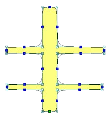
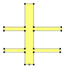
Corner Fit
The Corner Fit control determines how accurately the vectors are fitted to the corner edges in an image.
Loose
Tight
Loose
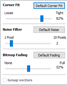
Loose will create smooth curves that may not follow corners very precisely, but will create smooth free-flowing vectorboundaries, with few nodes.
Tight
Tight inserts nodes to ensure the vector accurately follows the color boundary, to create sharp detail.
When using the Trace Color option it's sometimes useful to link a region of color's together, fit vectors and then link a new region or color's together, un-check the replace existing vectors option and fit another set of vector boundaries.
Noise Filter
The Noise Filter slider controls the minimum size of pixels that are traced / vectorized, preventing small unwanted vectors or noise being created.
For example, if an image contains single or very small clusters of pixels that aren't needed for machining a design. Then using the noise filter slider set at 4 pixels will ignore 2 x 2 or smaller pixel clusters.
Bitmap Fading
The Bitmap Fading slider controls the shading of the image in the 2D View. This is useful to see the trace vectors more clearly over high-contrast images.
Preview
This will preview the result of the tracing of the bitmap. If you are not happy with the result provided, you can alter the settings and click on the button again to get an updated result.
Apply
When you are happy with the result of the preview you can click on the button to keep it.
Close
Closes the Trace Bitmap form.