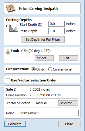
Prism Carving Toolpath

Prism carving gives a raised 'bevel' effect to shapes and letters similar to a 'hand carved' look.
Prism Carving uses an angled tool to create a raised prism shape on the top of the selected vectors. The tool will profile at a given depth creating a nice sharp finished shape such as the lettering shown in the image below. This is often paired with a Profile or Pocket toolpath to carve the vertical edge around the shapes or clear out the material between them. This type of toolpath is often, though not exclusively, used on lettering.

Cutting Depths
Start Depth (D)
Start Depth (D) specifies the depth at which the Prism Carving toolpath is calculated from. When cutting directly into the surface of a job the Start Depth will often be Z0. If machining into the bottom of an existing pocket or stepped region, the depth of the pocket/step that you are starting from must be entered here.
Prism Depth
This sets the depth of the Prism Carving toolpath relative to the Start Depth, the total depth of the base of the prism shape (within the material) will be the combination of the Start and Flute Depth. This depth is particularly important to set correctly as if it is too shallow then the prism shape may be truncated so it will have a flat top (shown in the image below right). The minimum depth needed to avoid this is determined by the widest point on the vector/s selected (W) and the angle of the tool (A). This can be calculated automatically by using the Set Depth for Full Prism function (see below for more details).
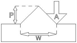
Full Prism
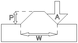
Truncated Prism
Set Depth for Full Prism
For this button to work you both need to select the vectors you plan to toolpath and also have selected the tool you are going to use, then when you click it, the Prism Depth will be set to the minimum required to ensure a full point on the prism for the current selection/tool.
Tool
Clicking the button opens the Tool Database from which the required tool can be selected. See the section on the Tool Database for more information on this. Clicking the Edit button opens the Edit Tool form which allows the cutting parameters for the selected tool to be modified, without changing the master information in the database.
Prism Carving is predominantly cut using a V-shaped cutter, having sharp tooling which is accurately sized is very important to getting good results. You should measure your cutters to make sure the size and angle of the v-bit are as per the manufacturers specifications as a variation of even 1 or 2° on the angle can make a big difference to the quality and precision of Prism carved shapes.
Direction
The direction of cut can be set to either Conventional or Climb machining, the choice for this will largely be dictated by the material being machined and the type of tool being used. See the section on Profile Toolpaths in the Reference Manual for more information on the differences between these.
Use Vector Selection Order
If this option is checked, ✓ the vectors will be machined in the order you selected them. If the option is not checked the program will optimize the order to reduce machining time.
General Toolpath Settings
This section of the toolpath form is common to a number of toolpath strategies.
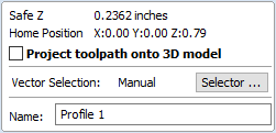
Safe Z
The height above the job at which it is safe to move the cutter at rapid / max feed rate. This dimension can be changed by opening the Material Setup form.
Home Position
Position from and to that the tool will travel before and after machining. This dimension can be changed by opening the Material Setup form.
Project toolpath onto 3D Model
This option is only available if a 3D model has been defined. If this option is checked, ✓ after the toolpath has been calculated, it will be projected (or 'dropped') down in Z onto the surface of the 3D model. The depth of the original toolpath below the surface of the material will be used as the projected depth below the surface of the model.
Vector Selection
This area of the toolpath page allows you to automatically select vectors to machine using the vector's properties or position. It is also the method by which you can create Toolpath Templates to re-use your toolpath settings on similar projects in the future. For more information, see the sections Vector Selector and Advanced Toolpath Templates.
Name
The name of the toolpath can be entered or the default name can be used.