Rotary Machining and Wrapping
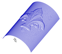
VCarve Pro can 'wrap' flat toolpaths around a cylinder to provide output to CNC machines which are configured with a rotary axis / indexer. The image below shows a flat toolpath wrapped around part of a cylinder.
The toolpaths can be visualized wrapped within the program:
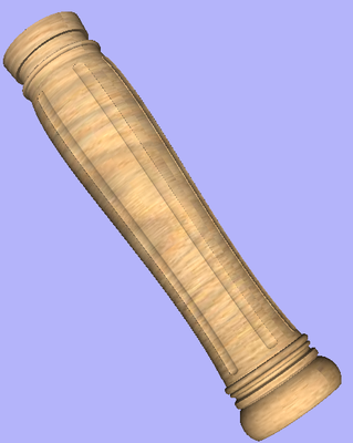
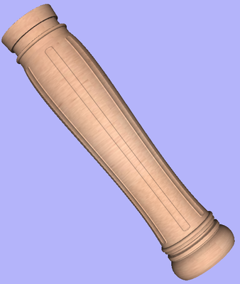
VCarve Pro can also visualize a wrapped model within the program by drawing the shaded composite model wrapped.
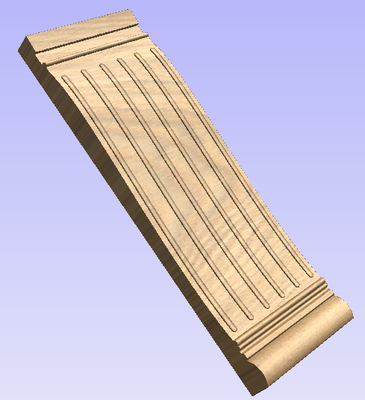
Cross section of a table leg modeled flat
Toolpath wrapping switched on
VCarve Pro also has the ability to draw the toolpath simulation wrapped. Although this is very useful for getting a feel for how the finished product will look, it is important to realize that the wrapped simulation may not be a 100% accurate representation of how the finished product will look. An example of potential difference would be if you drilled holes in your rotary job. In the actual work piece these will obviously just be round holes, in the wrapped simulation these may appear as distorted ovals due to the 'stretching' process which takes place when we wrap the flat simulation model for display.
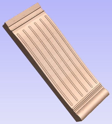
Simulated fluting toolpath flat
Toolpath wrapping switched on
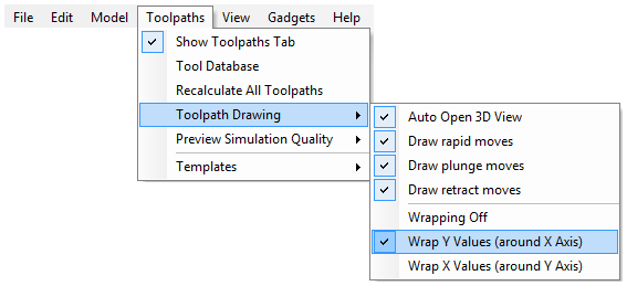
All the wrapped toolpath and model drawing is controlled using the 'Toolpath Drawing' options on the Toolpaths menu. To switch on wrapped toolpath and model drawing use Toolpaths Menu ► Toolpath Drawing ► Wrap Y Values (around X axis):
It is important to realize that there are a huge number of possible combinations of machine controller and axis orientations for rotary axis / indexers. This means it is impractical for Vectric to supply a pre-configured post-processor for every possible combination as standard. We include some wrapping post-processors in the default post-processor list as standard.
We also ship a copy of those post-processors in the Application Data Folder which can be accessed from the File Menu ► Open Application Data Folder.
Under this folder (shown as C:\ProgramData\Vectric\[ProductName]\V[ProductVersion] in the example shown below, this will be different on different operating systems) copies of the wrapped post-processors are stored in a sub-folder called 05-Wrapped:
C:\ProgramData\Vectric\VCarve Pro\V[ProductVersion]\PostP\05-Wrapped
Examining these posts may be helpful if you need to configure a post of your own. If Vectric have not supplied as standard a post for your machine configuration please refer to the Post Processor Editing Guide accessible from the Help menu of the program for information on how to configure a post-processor and also look at the standard rotary posts Vectric supply.
You should also look at the Vectric forum (www.vectric.com/forum) to see if anyone else has already configured a post for your configuration or one similar. If, after looking at these resources you are still unsure of what needs to be done for your machine, please feel free to contact support@vectric.com for help. However, please note that we cannot guarantee to write a custom rotary post-processor for every individual requirement.
Creating a file for rotary / wrapped machining
To simplify working with rotary / wrapped machining, VCarve Pro is supplied with a number of 'gadgets' to automate many of the common processes used in creating a job for rotary machining.
The first step for any rotary machining job is to run the 'Wrapped Job Setup' gadget before you open a new or existing file by selecting Gadgets ► Wrapped Job Setup from the main menu.
The Wrapped Job Setup dialog shown below will be displayed
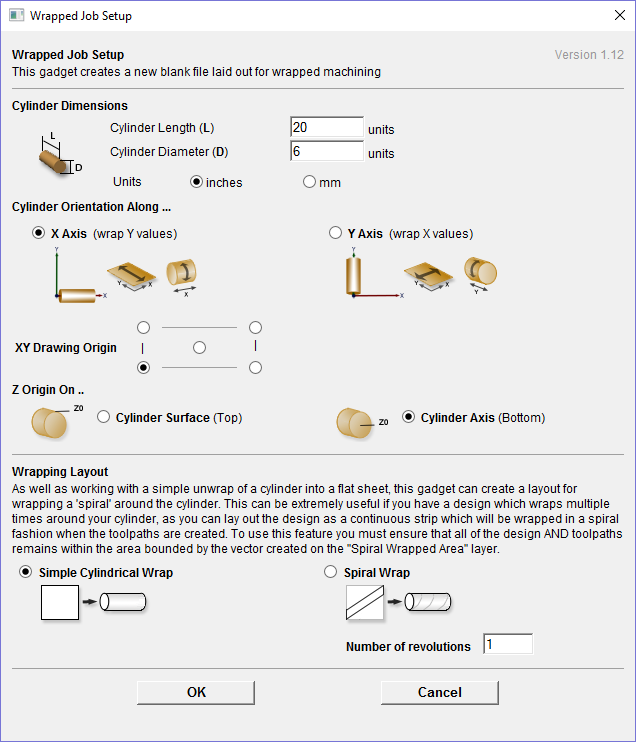
The form is divided into two main sections which we will discuss separately. The top part of the form allows you to enter details about the cylinder you will be machining on and your machine configuration. The bottom section of the form offers options on how the 2D view will be laid out.
Cylinder Dimensions - Here you specify the size of the finished cylinder you will be working on. From these dimensions the gadget will calculate the circumference of the cylinder surface which along with the length of the cylinder will control the width and height of the 2D job. The diameter will also be used to set the thickness of the job in the program to the radius of your cylinder.
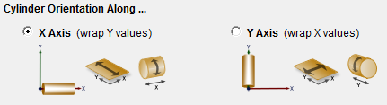
Cylinder Orientation Along - This section is used to tell the program how you have your rotary axis aligned on your machine. The images show the two supported options. If the centerline of your rotary axis is aligned along the X Axis of your machine pick the first option, otherwise the second. The gadget will remember your choice the next time it is run, so you should only have to make this choice once.
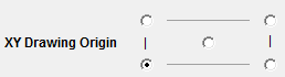
XY Drawing Origin - Here you can specify where the XY zero origin will be placed on your job. These options correspond to the same fields on the normal 'Job Setup' form within the program. Most people would use the default Bottom Left Corner, but for some jobs you may prefer to have the XY origin in the Center.
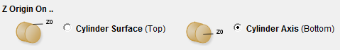
Z Origin On - This section determines whether the Z Origin is set to the surface of the material or the base (center of cylinder). These settings can be over-ridden when the toolpath is actually saved, but we would strongly recommend the 'Cylinder Axis' is selected for rotary machining. The reasons for this are detailed in the note below.
Note: Z Origin for Rotary Toolpaths
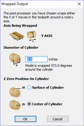
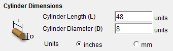
When you output a toolpath via a wrapping post-processor the form shown at the left will be displayed (this is for a post processor which wraps Y values around a cylinder aligned along the X axis) ...
You have the choice of specifying if the tool is being zeroed on the center of the cylinder or the surface. When you are rounding a blank, you cannot set the Z on the surface of the cylinder, as the surface it is referring to is the surface of the finished blank. We would strongly recommend for consistency and accuracy that you always choose 'Center of Cylinder' when outputting wrapped toolpaths as this should always remain constant irrespective of irregularities in the diameter of the piece you are machining or errors in getting your blank centered in your chuck.
A useful tip for doing this is to accurately measure the distance between the center of your chuck and a convenient point such as the top of the chuck or part of your rotary axis mounting bracket. Write down this z-offset somewhere, and zero future tools at this point and enter your z-offset to get the position of the rotary axis center
Another reason for choosing 'Center of Cylinder' is that some controls will be able to work out the correct rotation speed for the rotary axis based on the distance from the center of rotation. If the Z value is relative to the surface, the control would need to know the diameter or radius of the cylinder at Z zero.
The bottom section of the form offers two choices for how the job will be set out.
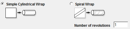
As well as working with a simple unwrap of a cylinder into a flat sheet; this gadget can create a layout for wrapping a 'spiral' around the cylinder.
This can be extremely useful if you have a design which wraps multiple times around your cylinder, as you can lay out the design as a continuous strip which will be wrapped in a spiral fashion when the toolpaths are created.
To use this feature you must ensure that all of the design AND toolpaths remains within the area bounded by the vector created on the
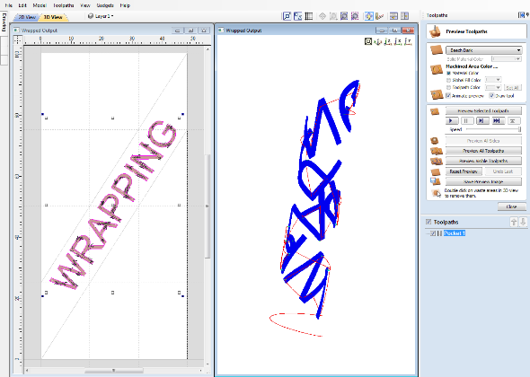
If you choose the 'Spiral Wrap' option, enter the number of times you want your design to wrap around the cylinder. The screenshot below shows a simple 3 turn wrap in the 2D view and the wrapped toolpath.
Vector Layout
As well as creating a job at a suitable size for wrapping toolpaths, if this gadget is run from VCarve Pro, it will create a number of vectors which can be very useful when creating your wrapped job.
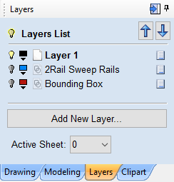
The vectors are created on their own individual layers and by default these layers are switched off to avoid cluttering up your work area. To switch on the layers, display the 'Layer Control' dialog (Ctrl+L is the shortcut to show / hide this). To show / hide the layer simply click on the check box next to the layer name.
2Rail Sweep Rails - This layer contains two straight line vectors which can be used to sweep a profile along if you are creating a shaped column.
Bounding Box - If you have chosen the 'Simple Cylindrical Wrap' option, this layer contains a rectangular vector covering the entire job area. This vector is useful if you are going to machine the complete surface of the cylinder.
Spiral Wrapped Area - If you selected the 'Spiral Wrap' option, this layer (which is visible by default) holds the vector bounding the area your design should be placed in to wrap correctly. This vector should also be used as a machining boundary if you are machining the complete surface of the cylinder.
In addition to the vectors created on layers, if you selected the 'Spiral Wrap' option, the gadget will create a series of horizontal and vertical guidelines to assist you in laying out your project.
Creating a Simple Wrapped Toolpath - Step by Step
1) Ensure you have a wrapping post processor for your controller and axis configuration installed in the PostP folder (see above).
2) Start a new job using the Wrapped Job Setup gadget - This must be run without a file open. When you start the program, before opening a new or existing file, select Gadgets ► Wrapped Job Setup from the main menu.
3) The Wrapped Job Setup dialog shown below will appear...
This dialog lets you specify the size and orientation of the cylinder you are machining on and also the axis the rotary axis is aligned with on your machine. After filling in the values and pressing OK the form will close and a new job will be created within the program. The size of the job will match the size of a sheet of paper wrapped around the surface of a cylinder of the size you specified. The thickness of the material will be set to the radius of your cylinder.
4) You can now create toolpaths within the job as normal. The example below demonstrates a piece of text machined with a pocketing toolpath 0.1 inch deep.
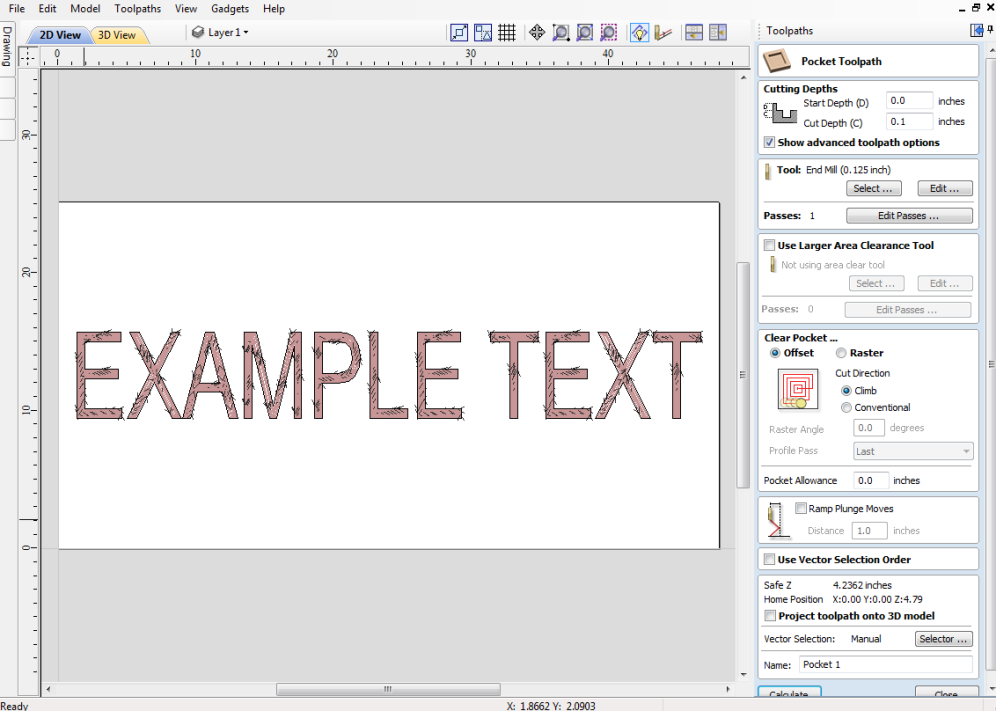
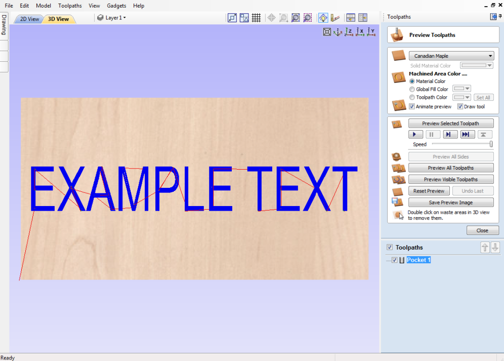
In the 3D view you will see the normal 2d toolpath ...
5) We can now see what this toolpath will look like when it is wrapped for output on a rotary axis.
Select Toolpath Menu ► Toolpath Drawing ► Wrap Y/X Values (Around X/Y Axis) from the Main Menu.
Note that for clarity we have un-checked View ► Color Shaded View. Depending on your machine setup, you should choose either 'Wrap Y Values (around X axis)' or 'Wrap X Values (around Y axis)' and this choice should match the choice you made for cylinder orientation in the 'Wrapped Job Setup' gadget in step 2.
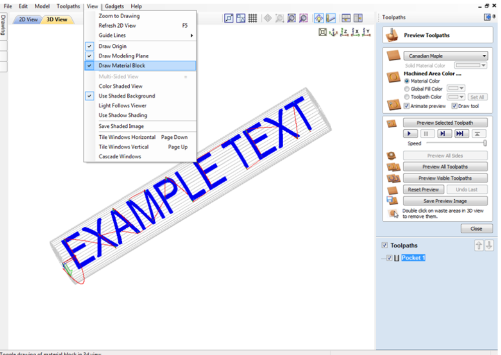
6) In the 3D view you should now see your 'flat' toolpath wrapped around the axis of your choice. To help with visualization, check ✓ the menu option 'View - Draw Material Block' as shown in the screen shot below.
7) Now you can save the toolpath using the wrapping post-processor copied into the PostP directory in Step 1. Select your 'Wrapping' post-processor and the 'Wrapped Output' dialog will appear as shown below ...
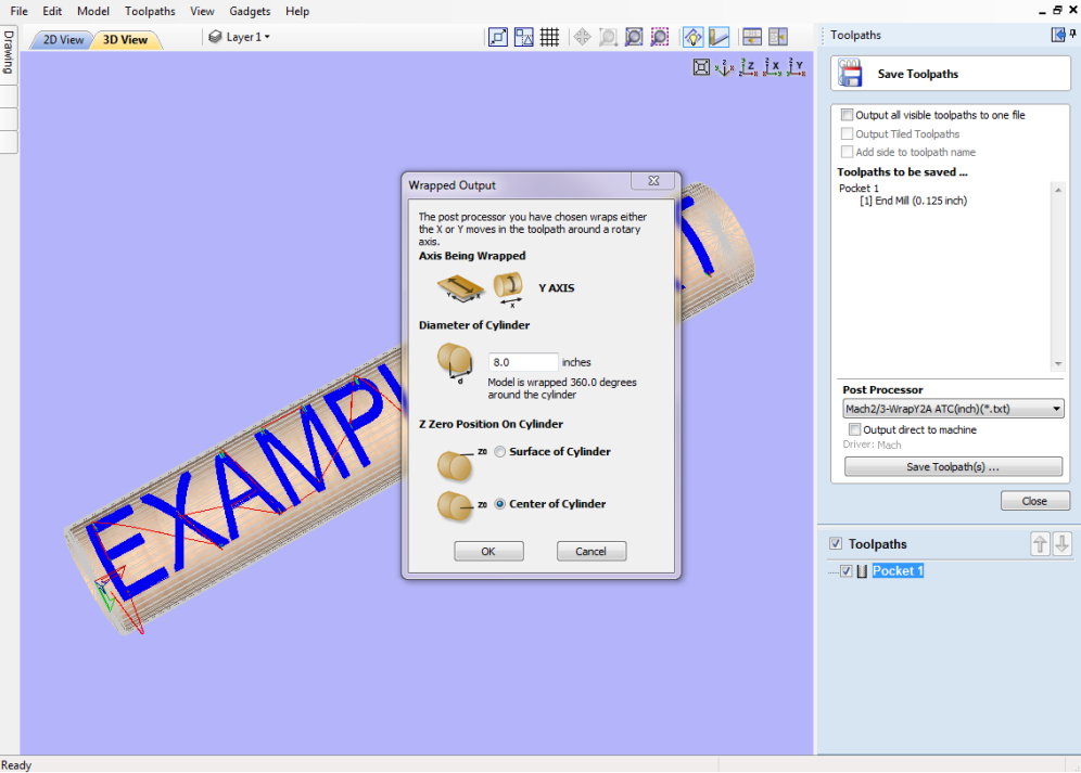
Note that in the example wrapping post-processor is selected (it has 'Wrap' as part of the name to distinguish it from a normal post-processor). Normally you will not need to change the values on this form other than possibly 'Z Zero Position On Cylinder' the first time you run it. The rest of the values are filled in automatically based on the settings from the post-processor and the material thickness which should have been set to the radius of your cylinder by the 'Wrapped Job Setup' gadget in step 2.
For the Z-Zero position, we would strongly recommend that you choose 'Center of Cylinder' as this should always remain constant irrespective of irregularities in the diameter of the piece you are machining or errors in getting your blank centered in your chuck. A useful tip for doing this is to accurately measure the distance between the center of your chuck and a convenient point such as the top of the chuck or part of your rotary axis mounting bracket. Write down this z-offset somewhere, and zero future tools at this point and enter your z-offset to get the position of the rotary axis center. If you are roughing an oversize blank, you MUST zero from the center of the cylinder, as the 'Surface of Cylinder' option refers to the surface of the final blank NOT your rough blank.
This has just been a brief overview of how wrapped machining works, and Vectric supply a number of other 'gadgets' to help perform common rotary machining tasks such as rounding square stock, creating fluted columns, laying out 'barley-twist' spirals etc. See Gadgets for more information.