Object Selection Tools
Once vectors have been created within Cut2D Laser Desktop or have been imported from other design software packages you may want to make changes to them. These changes may be to prepare for machining or for use as construction vectors for making 3D shapes using the Modeling Tools. There are a number of functions for editing vectors which will be covered in this section of the manual. All the icons under the Edit Vectors section of the Drawing Tab will be referenced along with the icons under the Align Objects section of the menu.
Editing Modes
From the 2D view a vector can be selected and then three different editing modes allow different dynamic edits to be made to the vector(s) depending on which option is selected from the Edit Vectors section.
The three editing modes are:
By default the software is normally in the Vector Selection mode.Vector Selection Mode
Selected from Edit Vectors section.
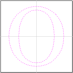
When the Vector Selection Tool is chosen, the selected vectors are shown as dotted magenta lines. Vectors need to be selected before any of the editing tools such as scaling and moving etc. can be used.
Vector selection methods
Multiple vectors can be selected in the following ways:
-
Manual multiple selection:
Hold down the Shift key while clicking the Left mouse button on each vector required. Objects can be deselected by simply clicking on the object again with a Shift key pressed.
-
Moving the cursor from Left to Right selects only fully enclosed objects:
Click and drag the left mouse button moving from Left to Right selects all objects completely inside the selection rectangle.
-
Moving the cursor from Right to Left selects all objects inside or touching the selection rectangle:
Click and drag the left mouse button moving from Right to Left selects all objects inside the selection rectangle + any that the selection touches.
-
Pressing the keyboard keys Ctrl+A will select all vector objects in the design:
Selected vectors are displayed as dotted magenta lines.
Deselecting Vectors
Selections can be cancelled by:
- Left clicking on an area outside the selection
- Pressing the Esc key
-
Pressing the Right mouse button and clicking Selection ► Unselect All from the pop-up menu.
You must click on the white drawing background to get this option in the pop-up menu.
Node Editing Mode
- See Also:
- Node Editing Shortcut Keys
The Node Editing tool can be selected from the Editing window or by pressing the Keyboard shortcut N to toggle between Selection and Node Editing modes.

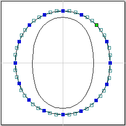
Vectors selected

Bezier node editing
When the Node Editing tool is active the cursor changes to a Black Arrow indicating that individual points (nodes) can be edited. Nodes can be interactively moved by clicking and dragging the left mouse button on a node to select and move the node to a new position.
The shape of lines, arcs and Bezier (curve) spans can be edited by clicking and dragging on the nodes or control points to move them. Multiple nodes and control points can be selected and moved by using the multiple selection options such as the Shift key and dragging to make a selection.
If you right click on nodes or spans a context sensitive popup menu will be displayed which allows you to insert or delete points and nodes, cut the vector, move the start point etc.
Node editing vectors is a very powerful way to be able to make changes to the vectors in your part.
Smart Snapping combined with Distance Snapping or Quick Keys can give more accuracy when dragging nodes.
Interactive Selection Mode
The Interactive Move, Rotate, Scale Selection tools can be used to quickly and easily modify vectors and components.
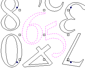
Clicking twice on one of the selected objects and the interactive scaling, movement and rotation handles are displayed in the same way as selecting this icon. Lines, Arcs and Bezier spans will be displayed as dotted magenta lines and text and grouped objects will be displayed as solid magenta lines:

When in this mode the mouse is used to click on one of the handles which has appeared on the selected Vector/s. Each handle is used for a specific editing operation as detailed here:
| Grip point | Default Action | Keyboard Overrides |
|---|---|---|
| Middle | Move the vectors | Alt Move the selected objects in one axis |
| Corner (White) | Scale the vectors proportionally. |
Alt Scaling non-proportionally Shift Scale around the center |
| Edges (White) | Scale the vector in one axis. | Shift Scaling proportionally |
| Corner (Black) | Rotate the vectors | Alt Rotate in 15° increments |
To deselect objects,
- Click the white background unless Shift is pressed.
- Press Esc
- Right click menu ► Unselect All