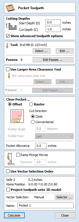
Pocketing Toolpath

This option opens the Pocket Toolpath form for machining 2D pockets. These toolpaths automatically compensate for the tool geometry - both diameter and angle.
Cutting Depths
Start Depth (D)
Specifies the depth at which the pocket toolpath is calculated. When cutting directly into the surface of a job the Start Depth will usually be 0. If machining into the bottom of an existing pocket or stepped region, the depth of the pocket / step must be entered.
Cut Depth (C)
The depth of the toolpath relative to the Start Depth.
Tool
Clicking the button opens the Tool Database from which the required tool can be selected. See the section on the Tool Database for more information on this.
Clicking the button opens the Edit Tool form which allows the cutting parameters for the selected tool to be modified, without changing the master information in the database.
Specify Pass Depths
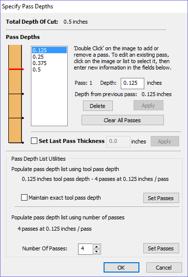
The Pass Depths section at the top of the form shows a list of the current pass depths. The relative spacing of the passes is indicated in the diagram next to the list. Left click on a depth value in the list, or a depth line on the diagram, to select it. The currently selected pass is highlighted in red on the diagram.
To edit the depth of the selected pass, change the value in the Depth edit box and click.
The button will delete the selected pass.
The Passes button will delete all the passes.
To add a new pass, double left click at the approximate location in the passes diagram that you wish to add the pass. A new pass will be added and automatically selected. Edit the precise Depth value if required and then click .
The Set Last Pass Thickness option will enable an edit box where you can specify the last pass in terms of the remaining thickness of material you wish to cut with the last pass (instead of in terms of its depth). This is often a more intuitive way to specify this value.
Pass Depth List Utilities
This section of the form includes two methods for creating a set of passes in one go.
The first method sets the passes according to the Pass Depth property of the selected tool.
This is initially the default method used by VCarve Desktop when it creates profile passes. The step size is varied to try and optimize the number of passes (see above) unless the Maintain exact tool pass depth option is checked ✓.
The second method creates evenly spaced passes according to the value entered in the Number Of Passes edit box.
To apply either method click the associated button to create the resulting set of pass depths in the passes list and diagram.
Use Larger Area Clearance Tool
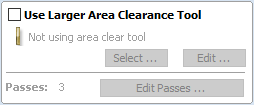
If this option is selected two tools are used to clear the pocket. A large tool to do the bulk of the area clearance and a smaller tool (the first tool selected) to remove the remaining material and do a final profile pass.
When a pocket toolpath is created, the Pass Depth value associated with the selected tool (part of the tool's description in the Tool Database) is used to determine the number of passes needed to pocket down to the specified Cut Depth. However, by default VCarve Desktop will also modify the tool step down by up to 15%, if by doing so it is able to reduce the total number of passes required to reach the desired cut depth. It is usually desirable to benefit from the significantly reduced machining time of cutting pockets using less passes if possible.
Nevertheless, there are some occasions where the exact step downs for a given profile pass needs to be more precisely controlled - when cutting into laminated material, for example. The Passes section of the Pocket Toolpath page indicates how many passes will be created with the current settings. The button will open a new dialog that enables the specific number and height of passes to be set directly.
Clear Pocket
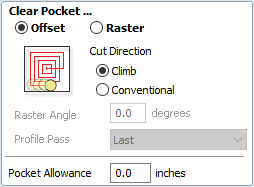
There are two choices of the type of fill pattern that will be used to clear away the area to be machined with the Pocket Toolpath, Offset and Raster.
 Offset
Calculates an offset area clearance fill pattern to machine inside the selected vector(s). Options for Cut Direction to be either: Climb (CCW) cutting direction Conventional (CW) cutting direction.
 Raster
Calculates a Raster based area clearance fill pattern to machine inside the selected vector(s). Cut Direction for the final pass to be either:
- Climb (CCW) cutting direction
- Conventional (CW) cutting direction
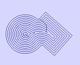
Clear Pocket - Offset Strategy
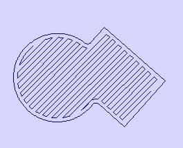
Clear Pocket - Raster Strategy
Raster Angle
Between 0 and 90°, where 0° is parallel to the X axis and 90° parallel to the Y axis.
Profile Pass
Used to clean up the inside edge after machining the pocket. This can be done either before the rastering (First) or after the rastering (Last). If 'No Profile Pass' is selected, you will need to calculate a profile pass manually to machine the pocket to size.
Pocket Allowance
This option is used to leave material on the inside of the pocket for the Profile Pass to clean-up. This is often very useful for ensuring the cutter does not mark the edge surface of the pocket when roughing out.
A positive value in the allowance box will lead to an undercut of the selected closed vector. I.E. the pocket will be smaller than the chosen vector, by the specified value.
A negative value would result in an overcut of the selected closed vector. I.E. the pocket will be larger than the chosen vector, by the specified value.
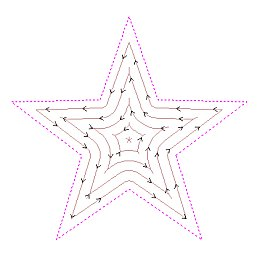
Offset larger than 50%
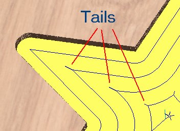
Tails to clean out corners
Ramp Plunge Moves
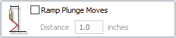
The cutter can be ramped over a distance into the pocket instead of plunging vertically. This approach reduces heat build-up that damages the cutter and also reduces the load on the spindle and z axis bearings.
Use Vector Selection Order

If this option is checked, ✓ pockets will be machined in the order you selected them. If the option is not checked the program will optimize the order to reduce machining time.
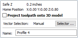
Safe Z
The height above the job at which it is safe to move the cutter at rapid / max feed rate. This dimension can be changed by opening the Material Setup form.
Home Position
Position from and to that the tool will travel before and after machining. This dimension can be changed by opening the Material Setup form.
Project toolpath onto 3D Model
This option is only available if a 3D model has been defined. If this option is checked, ✓ after the toolpath has been calculated, it will be projected (or 'dropped') down in Z onto the surface of the 3D model. The depth of the original toolpath below the surface of the material will be used as the projected depth below the surface of the model.
Vector Selection
This area of the toolpath page allows you to automatically select vectors to machine using the vector's properties or position. It is also the method by which you can create Toolpath Templates to re-use your toolpath settings on similar projects in the future. For more information, see the sections Vector Selector and Advanced Toolpath Templates.
Name
The name of the toolpath can be entered or the default name can be used.