Sketch Carving
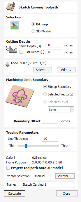
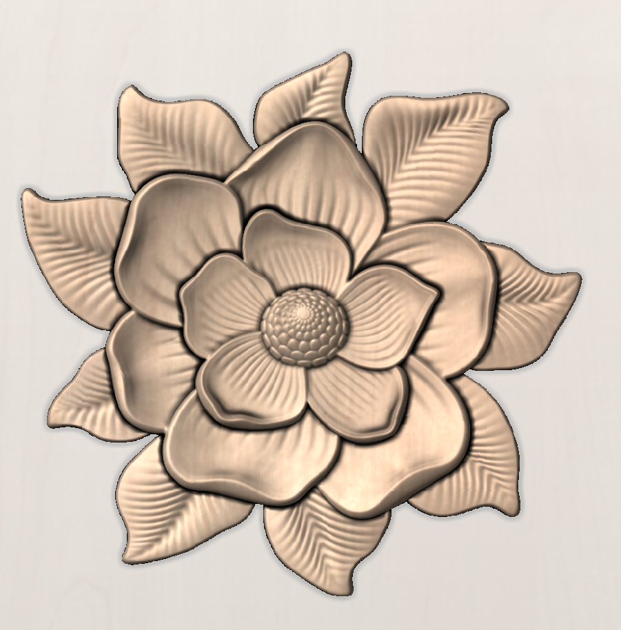
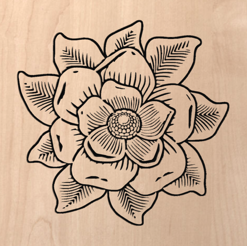
This tool uses the differences in contrast between areas of a Bitmap image or a 3D model to create a toolpath and create a Sketching style carving design of the outline.
Selection
This allows the User to indicate if the selecting image is either:
Bitmap
An image file Imported in the following format .BMP, .JPG, .GIF, .TIF, .TIFF, .PNG, .JPEG
3D Model
A 3D file import in the following format .STL, .V3M, .3DM, .SKP, .RLF, .3DS, .ASC, .PRJ, .X, .DXF, .LWO, .WRL, .OBJ
Cutting Depths
Start Depth (D)
This specifies the depth at which the toolpath is calculated from.
When cutting directly into the surface of a job the Start Depth will often be 0. If machining into the bottom of an existing pocket or 3D region, the depth needs be entered.
Cut Depth (C)
The depth of the toolpath relative to the Start Depth.
Tool
Clicking the button opens the Tool Database from which the required tool can be selected. See the section on the Tool Database for more information on this. Clicking the button opens the Edit Tool form which allows the cutting parameters for the selected tool to be modified, without changing the master information in the database. Hovering the mouse cursor over the tool name will display a tool tip indicating where in the Tool Database the tool was selected from.
Machine Limit Boundary
Choose what to use as the outer boundary for the Sketch Carving toolpath
Bitmap Boundary
Using the external edge of the bitmap or 3D file as the boundary for the tools operation.
Selected Vector
Allows a vector to be used as a boundary to limit the extent of the toolpath creation.
Hold SHIFT and selected the desired Vector to use as the boundary after selecting the Bitmap or 3D model you are Sketch Carving.
Selected Level
Allows a Component Level to be selected to use the components on that level for a boundary to limit the extent of the toolpath creation.
Boundary Offset
Increase the Machining limit outside of the boundary selected above but the distance used here. The Default value is 0.
Tracing Parameters
The Line Thickness slider will allow you to adjust the weighting of your sketch lines created from your 3D model or Bitmap image.
This can slide between 0 and 100.
The higher the value the thicker and heavier the sketch carve lines will be but the less detail will be picked out.
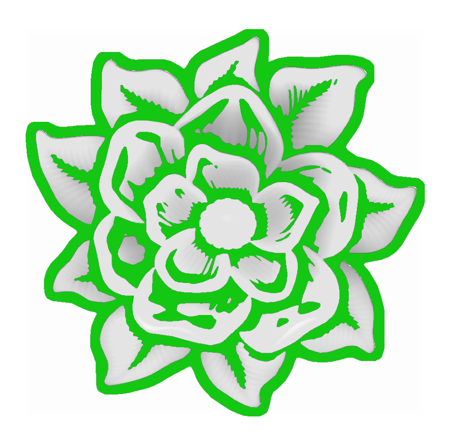
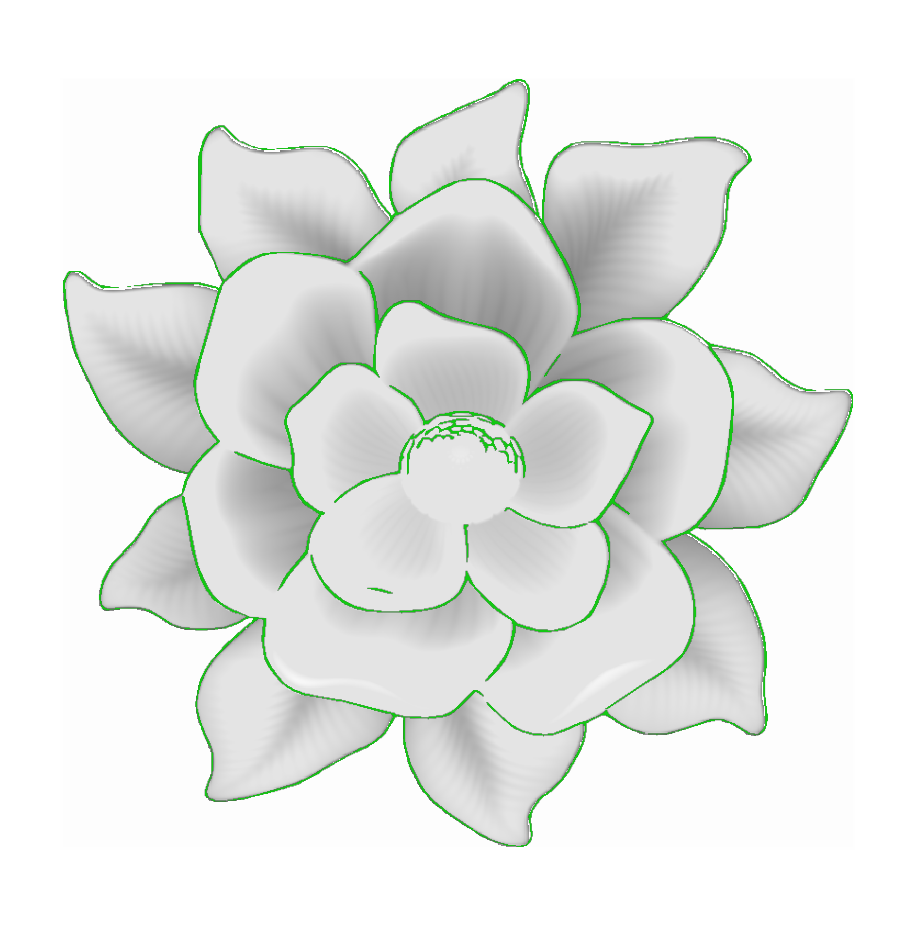
You can see here the green hightlighted area shows the area which will be cut in this toolpath, with the lower Line Thickness picking out more lighter details, but overall cutting a much shallower area, while the Thicker Line Thickness will apply more heavily to the largest areas while not cutting the finer details.
By reviewing the Sketch Carves Green Highlights you can get a good idea how the toolpath will cut before calculating it.
Position and Selection Properties
Safe Z
The height above the job at which it is safe to move the cutter at rapid / max feed rate. This dimension can be changed by opening the Material Setup form.
Home Position
Position from and to that the tool will travel before and after machining. This dimension can be changed by opening the Material Setup form.
Project toolpath onto 3D Model
This option is only available if a 3D model has been defined. If this option is checked, ✓ after the toolpath has been calculated, it will be projected (or 'dropped') down in Z onto the surface of the 3D model. The depth of the original toolpath below the surface of the material will be used as the projected depth below the surface of the model.
Note:
When a toolpath is projected onto the 3D model, its depth is limited so that it does not exceed the bottom of the material.
Vector Selection
This area of the toolpath page allows you to automatically select vectors to machine using the vector's properties or position. It is also the method by which you can create Toolpath Templates to re-use your toolpath settings on similar projects in the future. For more information, see the sections Vector Selector and Advanced Toolpath Templates.
Name
The name of the toolpath can be entered or the default name can be used.