User Guide
- 01. Interface Overview
- 02. Getting Started - Introduction
- 03. Getting Started - The CNC Workflow
- 04. Getting Started - One-Time Setup
- 05. Getting Started - Example Project
- 06. Intermediate - 2D Design and Management
- 08. Intermediate - Creating a Rotary Job
- 09. Intermediate - Simple Rotary Modelling using 2D Toolpaths
- 10. Advanced - Rotary Machining and Wrapping
- 15. Advanced - Post-Processor Editing
01. Interface Overview
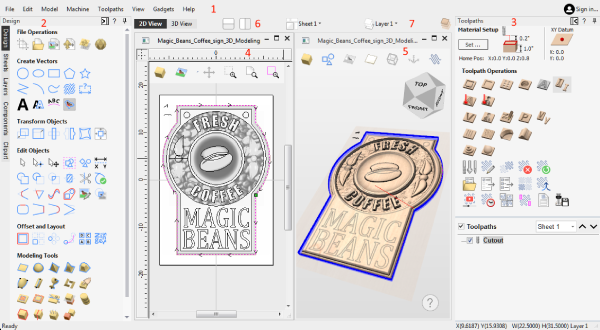
- The Main Menu Bar (the Drop Down Menus) along the top of the screen (File, Edit, Model, Machine, Toolpaths, View, Gadgets, Help) provides access to most of the commands available in the software, grouped by function. Click on any of the choices to show a Drop-Down list of the available commands.
- The Design Panel is on the left side of the screen. This is where the design tabs can be accessed and the icons within the tabs to create a design.
- The Toolpath Tab is on the right side of the screen. The Top section of the toolpaths tab houses all of the icons to create, edit and preview toolpaths. The bottom half shows you toolpaths that you have already created.
- The 2D Design window is where the design is drawn, edited and selected ready for machining. Designs can be imported or created directly in the software. This occupies the same area as the 3D View and the display can be toggled between the two using F2 and F3 or the tabs at the top of the window.
- The 3D View is where the composite model, toolpaths and the toolpath preview are displayed, and can also be used to create your Vectors, 3D models and edit them both.
- If you wish to see the 2D and 3D views simultaneously, or you wish to switch your focus to the Toolpaths tab at a later stage of your design process, you can use the interface layout buttons (accessible in the 2D View Control section on the Drawing Tab) to toggle between the different preset interface layouts.
- Quick Drop down menus can be accessed here to change the current Layer, Sheet or Component Level you are working on.
 Managing the Interface
The tool pages have Auto-Hide / Show behavior which allows them to automatically close when not being used, thus maximizing your working screen area.
The software includes two default layouts, one for designing and one for machining, which can automatically and conveniently set the appropriate auto-hide behavior for each of the tools pages. Toggle layout buttons on each of the tools pages allow you to switch the interface as your focus naturally shifts from the design stage to the toolpathing stage of your project.
Accessing Auto-hidden tabs
If a tools page is auto-hidden (because it is currently unpinned, see pinning and unpinning tools pages, below), then it will only appear as a tab at the side of your screen. Move your mouse over these tabs to show the page temporarily. Once you have selected a tool from the page, it will automatically hide itself again.
Pinning and unpinning tools pages
The auto-hide behaviour of each tools page can be controlled using the push-pin icons at the top right of the title area of each page.


Default layout for Design and Toolpaths
Cut2D Desktop has two default tool page layouts that are designed to assist the usual workflow of design, followed by toolpath creation.
In all three of the tools tabs there are 'Switch Layout' buttons. In the Drawing and Modeling tabs, these buttons will shift the interface's focus to toolpath tasks by 'pinning-out' the Toolpaths tools tab, and 'unpinning' the Drawing and Modeling tools tabs. In the toolpaths tab, the button reverses the layout - unpinning the toolpaths page, and pinning-out the Drawing and Modeling pages.You can toggle between these two modes using the F11 and F12 shortcut keys.
Help ?
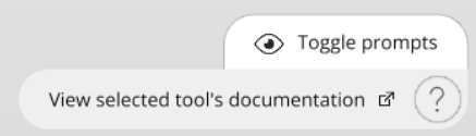
In all forms is a ? Icon which will take you to the appropriate Help Contents page to cover the tool form you are on in detail.

3D View Help Prompts
The Help Prompts will track your current tool or action and offer quick access to relevant Help documentation or tips on the current tool.
02. Getting Started - Introduction
Getting Started
Welcome to the vibrant Vectric community! You've made a great choice for getting the most from your CNC machine by using Vectric software. This short guide should help you to get your CNC machine cutting correctly in less than hour. Along the way we will highlight key concepts and tools in our full Reference Manual. These links will help you review each step in more detail and begin to develop your skills.
Overview
In the first section of this guide we will describe the main principles of CNC toolpath creation using Vectric software. All CNC projects follow a similar workflow and our software is designed to reflect these steps naturally and intuitively.
Next we will complete your one-time setup to licence your product and give you access to Vectric's online portal, V&Co, which we will use to automatically configure the software for your specific CNC machine.
In the final section we will run through a simple, but complete, CNC project from start to finish step-by-step. At the end of the project you should be confident that your CNC machine is correctly configured and you can cut vector drawings using a simple profile toolpath strategy.
03. Getting Started - The CNC Workflow
The Vectric Workflow
The Example Project will step you through all the stages of creating, toolpathing and cutting a simple line drawing. Most CNC projects share many common concepts and steps so before we complete our practical project, let's run through them.
The structure of a Vectric Job
All the information needed to describe a single CNC project is contained in a Vectric Job document (when saved they have the file suffixes *.crv or *.crv3d). A new job always begins by defining the area of a sheet of physical material that you intend to cut with your CNC machine.
Most jobs typically only involve one sheet of material, but more complicated projects may comprise multiple materials. Don't worry, your job's primary material sheet can be updated or new sheets of material added to your job later, as your design develops.
The drawings & images used to work on a material sheet can be created on layers to help manage more complicated designs. Similarly 3D model components can also be organised onto levels. By default there is always at least one layer and one level for each sheet in a new job. You can add more layers and levels to help organise more complicated projects.
Once your material sheet has been created in the Job Setup form, the software will show you a 2D & 3D view of your design space (which matches the dimensions of your current material sheet), each in their own window.
Above the view windows is the main toolbar which allows you to navigate through the structure of your CNC job and see what is currently being displayed in view windows below. It shows you the material sheet, design layer and 3D model level that you are currently working on (referred to as 'active').
What you see in the 2D & 3D design views below will reflect these current settings and any new shapes, components or toolpaths will be created in the active locations indicated. You can also change the active sheet, active layer or active level at any time directly from these controls.
More advanced projects can also represent both sides of a sheet of material. For a two-sided project an additional control above the views shows which side of the sheet is currently active. You can view the drawings, models and toolpaths associated with the top and bottom surface of each material sheet and swap the active side of the sheet in a consistent way to the other controls.
Initially your job will be empty and so your views will be blank, but in due course, Vectric's view windows will show all the layered drawings & images, 3D model components & toolpaths for the currently active material sheet.
The currently active locations are the same for both the 2D & 3D views i.e. creating a vector shape will place it on the same active sheet and active layer regardless of whether the 2D or 3D view is used.
You can, however, toggle the visibility of object types in each view independently using the visible items toolbar at the top of each view. This is helpful for focusing on different areas of your job at each stage of creating your CNC project.
Many of the software's tools can be used directly in either the 2D or 3D view.
In V12 some tools have not yet been extended to allow full interaction in the 3D - this is an ongoing transition. If in doubt, try click
Import, Draw or Trace artwork
Computer images are most often represented as a grid of coloured squares - these images are referred to as bitmaps and their constituent coloured squares are called pixels. Except for a few very specific cases, this representation is not *directly* useful for toolpath creation. Computer drawings (from CAD or illustration applications) are very different and are instead built from mathematically defined lines & curves.
This type of representation is referred to as vector or contour artwork. Vectric software can use both bitmap and vector artwork, but most types of toolpath can only be created from vector drawings. Suitable bitmaps with bold regions of similar colour (for example logos, cartoons, icons or signs) can, however, be used to create vectors from which many types of toolpath can then be generated - this process is called bitmap tracing.
Some external artwork file types contain only bitmaps (e.g. BMP, PNG, JPG), some contain only vectors but many can contain both (e.g. PDF, SVG, DWG/DXF).
Use the design artwork to create toolpaths
We use the vector artwork to define the shapes we want to cut. It is important to emphasise that the toolpath (the actual cutting moves your machine must make to leave your intended shape) is rarely, if ever, a direct conversion of the original artwork. The toolpath must be created taking into account a complex interaction of the material, your CNC machine's capabilities and the shape of your cutting tool.
"Sculpture, per se, is the simplest thing in the world. All you have to do is to take a big chunk of marble and a hammer and chisel, make up your mind what you are about to create and chip off all the marble you don’t want." - Paris Gaulois, 1879.
Toolpaths are therefore generated from source vector artwork but once created they are almost entirely indepenendent of the artwork that created them. Moving, editing or even deleting the source artwork used to generate a toolpath will not affect the toolpath - it must be actively re-calculated to reflect any changes.
This is a carefully considered Vectric design principle - although you may be prompted that a significant alteration to your job has occurred - your toolpaths will never change automatically 'behind your back'!
That said, toolpaths do retain a handy reference to the artwork that created them. If you choose to edit a toolpath it will try to locate it's orginal source artwork and re-select it. At this point you can simply recalculate it to reflect any changes you have made to that source artwork, but you can also choose to select additional or entirely different artwork.
Preview
As we've discussed, the actual motion of your CNC machine (the toolpath) required to cut al shape can be complex and difficult to interpret.
Luckily your software provides an extremely accurate preview of any toolpaths that you create by simulating them in a block of virtual material. In the Example Project we will use the Toolpath Preview to verify that the toolpaths are producing the shapes we want (and we can easily corrected them if not)!
This simulated preview is a hugely beneficial step that ensures you minimise costly mistakes in the real world (we all make them from time to time) but it also allows you to check the surface finish you can expect from different strategies under different conditions.
The Toolpath Preview uses exactly the same data that will be sent to your CNC machine. You can be confident that any cutting and surface finish issues that occur at the machine but which are not visible in the Toolpath Preview are almost always caused by a physical problem with the machine setup or tooling, which makes finding and fixing them a lot quicker!
Exporting the toolpath
Now we will be ready to export the toolpath, in the right format, ready to be loaded into our CNC machine's controller. Saving the toolpath will make use of a Post-Processor that is specific to your CNC machine. It will translate the movements contained in the toolpath into a toolpath file that is in the specific format required by your CNC machine's controller to load and run.
04. Getting Started - One-Time Setup
One-time setup
Before we can begin, however, we must complete a couple of one-time steps to ensure your newly installed software is correctly configured. We will start by showing you how to log in to Vectric's online portal, V&Co. Here you will be able to download many other tutorials & projects, clipart packs and software updates. It is also the place you will find your personal product license code and you can return to it any time should you need to recover this licence information or use the main product installer again for any reason in the future. We will also use V&Co to access our online Machine Database. We can use this to automatically configure your software for the make and model of your CNC machine. Licensing and configuring your software typically only needs to be completed once and if you are online they can both be completed almost entirely automatically with just a few clicks.
Licence Management & Your V&Co Account
It is important that your investment in our high quality CNC software is protected and that Vectric can continue to create great software in the future - you will, therefore, have a unique personal licence for the software that you have purchased.
This licence is associated with your Vectric V&Co account, and can be accessed at anytime via https://portal.vectric.com. To log in to your V&Co account you will need to use the email address (which must be uniquely yours) and password that you registered with us when your account was created - please keep these details safe. Your registered email address is the way by which we can verify your ownership of the software.
Important Note: you can reset your password at any time using your registered email account and the forgotten password link provided on the V&Co log in page. If you need to change your registered email address it is important to do this before you lose access to the one to which the software is registered. If you can no longer access your registered email, you will need to contact us directly at support@vectric.com but please note that you will now need to be able to provide independent and alternative proof of your identity and purchase.
Within your V&Co account there is a unique digital code for each piece of Vectric software you have purchased. When you first run our software on your laptop or PC you will be prompted to provide this information. If you are installing onto a computer that is online (i.e. with unrestricted internet access available) you can complete this process almost entirely automatically - this is the fastest and easiest method.
The software will simply launch your web browser and prompt you to log in to your portal account. The software will then show the appropriate license that is available to be linked. Simply accept the link and you're good to go!
Once you have completed this process after initial install you will not be required to do it again unless you change computers or need to re-install the software afresh. Your software is now uniquely licenced to you and your details will always be shown in the main interface - even when you are offline, or online but not logged-in.
You can also log into your V&Co account from within the software at any time when you are connected to the internet to enable additional online features and services such as your clipart collection or online tool database.
When logged-in, your software will indicate this in the top right corner of the main window. Please note, the one-time licensing of your software and routinely logging in when using your software are independent concepts. Your personal product licensing is unaffected by your V&Co logged-in status.
We have also ensured that you can complete the software licensing process without having a live internet connection. The process is less automatic and details of the steps can be found here.
CNC Machine Tool Configuration
The software supports hundreds of different types of CNC machine, so the the next thing we will need to do is configure the software for your particular make and model. Correct configuration comprises two elements - appropriate tool settings in the tool database for your CNC machine and setting the 'translation' file (the Post-Processor) needed to create a toolpath file that your specific machine tool controller can understand.
Tool Database
Configuring the software will create a default tool database with tool definitions include cutter movement speeds ("feedrates") that *should* be a reasonable starting point for you to edit the entries for the tool types that you have, according to the recommendations from your CNC machine manufacturer for each material. Appropriate tool settings are the result of a complex interaction of the tool's shape and design, the nature of the material you intend to cut and the strength and power of your CNC machine. Don't use any default settings without first considering whether they are appropriate for your circumstances.
We will look at the Tool Database in more detail in the Toolpath Creation section below.
Post Processors
Your software can create toolpath files for hundreds of different CNC machines and controllers. To achieve this, the software creates an internal representation of a toolpath. Only when this toolpath is saved does it get 'translated' into the specific format required by your CNC machine.
The translation instructions are contained in file called a Post-Processor (because it *processes* the toolpath *after* it has been created).
Post-Processors also determing whether the toolpath movements will be presented to the machine using metric or imperial units. This must typically match the units mode you have set on your CNC machine's controller (seek advice from the manufacturer if needed). Note, however, it doesn't matter what units where used to create the original toolpath within the software - any required conversion is automatically applied when the toolpath is saved through the Post-Processor.
Job Setup - Axis Orientation
Our software is specifically designed for 3-axis CNC Machines (with additional support for an optional rotary axis). As you look at your CNC machine, the normal conventional is that left and right movement is controlled by the X-axis, forward and backward movement controlled by the Y-axis and up and down movement is controlled by the Z-axis.
In our software the width of your job will typically be equivalent to the X-axis of your CNC machine and the height of your job to its Y-axis.
Be aware that some machines are orientated so that the X & Y axes are swapped as you look at them - left to right movement may be controlled by the Y-axis and vice versa.
Use your machine's control software to jog your machine independently in each axis to make sure your expectations are correct.
Although unusual, it is possible that some post-processors will swap the X & Y toolpath coordinates after you have created your toolpaths - effectively changing the apparent orientation of you job - but this is only recommended for users who are confident of their machine's configuration and usage and not recommended for the majority of users who might not be aware of the other issues this can cause. Check with your machine tool manufacturer if you have any doubts.
It can help Orientate yourself so that when you stand before the machine, when you jog the machine to move to a higher X position, it is moving Left to Right infront of you. This can help visualise how the project design you have made in the software will translate to the bed of your machine.
05. Getting Started - Example Project
Cutting a Calibration Pattern
For our quick introduction we are going to us a 2D Profile toolpath strategy to engrave a precisely sized and aligned rectangle, circle and star. This pattern will use all the steps we have outlined in The CNC Workflow. It will also allow us to check that the CNC machine is working correctly using some simple but important features of the design:
- The rectangle, circle & star should not appear warped or distorted.
- The dimensions of the carved shapes should exactly match the design.
- The alignment points of the 3 shapes should not show any discrepancies.
- The star is rotated slightly clock-wise and the carving should match the original orientation of the design with no unexpected reflections in X or Y.
At the end of this guide we will review these checks and suggest some troubleshooting tips if any of them are not as they should be.
Material, Tooling & Hold-Down
The XY dimensions of the design will be 100mm (4") so you will need a piece of material approximately 150mm (6") square or larger.
The precise thickness of material is not too important as the design will simply be carved into its surface at a depth of 1.5mm (1/16"). Any piece that is 3mm (1/8") thick or greater will therefore be fine. An offcut of plywood or mdf board would be ideal.
To avoid any chance of collision with clamps or cutting into a screw, the best starting method to hold down a small piece of material like this is to use double sided tape. Any heavy duty 'carpet' type tape will work, but you may need to experiment to find a brand that secures well, but can also be cleanly removed once the job is complete.
The toolpth will be created based on a V-bit, but the precise tool angles are not important. If you don't have a V-bit tool, then a small (3mm, 1/8" diameter or less) end mill or ball nose tool will also work but the cuts will be the broader so the calibration pattern may be a little bit more difficult to interpret.
To avoid any chance of collision with clamps or cutting into a screw, the best starting method to hold down a small piece of material like this is to use double sided tape.
Create the Job
- Click `Create a new file` to get started.
This opens the `Job Setup` form. All projects start with a job setup. Here is where we consider the physical dimensions of our design. Note that you do not necessarily need to define the whole material block at this point, just that area needed for your design - the design area can be subsequently positioned anywhere on a larger physical material block using the `XY Datum Position`, which your CNC machine will use as its reference starting point.
Like all forms in the software, you should simply work from the top to the bottom of the `Job Setup` form. Forms are typically laid out with the most significant, non-optional or most commonly updated fields at the top. Sensible defaults are provided for most form fields the first time they are accessed (fields will generally remember their previous setting, once you edit them) so initially you can simply ignore any fields you are not sure about. At the bottom of most forms are the buttons to (accept), or any changes you have made.
- The job setup form allows for projects that will be cut from both sides or using a rotary axis, but for now we will simply select `Single Sided`.
We will set the `Job Size` units according to your preference.
Note that your CNC machine controller will be set to expect toolpaths defined in either metric or imperial units and you will need to refer to your CNC manufacturer to determine your particular setting - the Post-Processor you select later will need to match the toolpath to the controller's requirements but this is entirely independent of the units you prefer for designing within the software - everything will be automatically converted, if necessary, when the toolpath file is created.
- Set the width & height of your new job to both be 150mm (6")
- Set the
- Click OK
Design the Calibration Artwork
Your project needs to start with design drawing. On the left-hand side of the screen there are a number of tabbed panels that provide access to various tools to help you to draw your design.
In due course, we will use our design to begin creating toolpaths for our CNC machine. The functions relating to toolpaths and toolpath strategies are located in another panel on the right-hand side of the screen. Initially this panel is hidden. Once our design is largely complete we will switch our focus to the toolpath panel on the right.
This is the typical workflow when creating a CNC project and so the software interface makes this switching of focus easy and intuitive.
For now let's continue to focus on the tools available in left-hand design panel.
The first thing we will do is create a simple 100mm Square, using the Rectangle tool in the Design Panel on the left. Witht he Rectangle tool open, click into the 3D View to place a default rectangle, and in the Edit Boxes on the Right and Bottom of the rectangle, click into each one and type 100.
This will create your Rectangle to be 100mm x 100mm.
Now press the F9 key on the keyboard, and your Rectangle Vector will now be centered in your work space.
Create our First Toolpaths
Now that our design drawing is complete we are ready to consider what toolpath strategy we should use to cut this shape accurately and efficiently.
The software interface can automatically hide the design tools panel and show the toolpath strategy tools panel using the 'Switch to Toolpath commands' button.
- Click on the 'Switch to Toolpath commands' button at the top of the 'Design' tab.
The toolpaths tab will now open on the right-hand side of the software. Here you will find all the tools relating to the creation, editing and saving of toolpaths.
Selecting the most appropriate toolpath strategy for a particular job is one of the toughest aspects of initially learning how to use your CNC effectively. Over time you will explore the different strategies available within this tab and our extensive tutorials and practical examples will to understand what each is used for.
For now we are going to use just the first strategy availble under the Toolpaths Operations - this is the Profile Toolpath.
Click on the Profile Toolpath button to open the 2D Profile Toolpath form.
Saving and Loading the Project
At this point we should probably save our project. Saving the project document using the File->Save menu, or the Ctrl+S shortcut-keys, is just like saving any other conventional application document (i.e. Microsoft Word etc.) and it will include all of your 2D design elements, 3D models and toolpath strategy settings in a `*.crv` or `*.crv3d` file. This is the file that you can come back to any time at a later date to continue your work or to duplicate as the basis of a new project.
Note that this is *not* the file that your CNC machine will read. Saving Toolpaths (see below) is the indepenendent process by which you specifically save the file from this project that your CNC machine needs. It may be helpful to think of the toolpath saving process as more like creating PDF files *from* your Word document - PDF files aren't typically reloaded or edited but they are ready for 'printing'.
Previewing the Toolpath
Before we begin getting our toolpath files over to our CNC machine there is still a *very* important step for us to do in the software. We can preview exactly how our CNC machine will move and what the material should look like after each toolpath is completed using the Preview Toolpaths command.
Saving Toolpaths - Post Processing
You now need to Post Process your Toolpath to save your toolpath out into a file which your CNC Machine will be able to read.
In this guide we will assume that you have completed the "Machine Configuration" Process either Manually or using one of the existing Online Configurations as seen here.
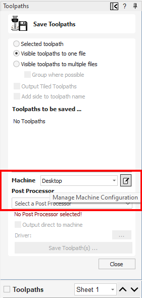
With that step complete, you just need to now open the "Save Toolpath" form, using the bottom right most icon in the Toolpath Panels icons.
Make sure your machine is currently selected in the Machine
Running Your Toolpath
Every CNC machine and controller is different. At this point you will need to refer to your CNC machine manufacturers instructions for the details of running your toolpath file, but we can provide some generally applicable information about the typical process you should expect.
Secure your material
Your piece of material will need to be secured to the machine's bed. This is typically done by clamping, screwing or gluing your material down (larger or more sophisticated machines may have vacuum hold-down). In the first two cases you must be very careful to avoid cutting into your clamps or screws. As we noted in the Job Setup, the toolpath file does not have to be the same size as the material so the simplest way to avoid clamps and screws is to make sure your job dimensions (and thus your toolpaths) are no larger then the unobstructed area of your material and that it is correctly positioned within this region.
Set your origins (datums)
The movements of all toolpaths are relative to the `XY datum position` you selected when you initially created your job (in our example we set the bottom-left corner, but it can also commonly be the center of your design), these are also often referred to as "origins". Now you must indicate to your CNC machine controller where this datum point is physically located on your material. This process is usually referred to as "setting the XY datum", "setting the XY origin" or "zeroing X & Y".
In effect, setting the XY datum will position where your toolpath will be cut on your material.
You will also need to indicate to your controller how deep into the material your toolpath will cut - the equivalent of positioning your toolpath within the material. This is often known as "setting the Z origin", "setting Z zero" or "zeroing Z".
Again at this point it is important to know what `Z Zero Position` setting you used when you created your Job in the software - in our example we set it to be on the surface of the material, but in some circumstances it is useful to set it to the base of the material block, or your CNC machine's bed.
Because this job was created with the `Z Zero Position` to on the `Material Surface`, you will need to jog your CNC machine so that the tip of the tool is touching the surface of the material and then use its control software to zero the Z position.
Alternatively you may have an automatic Z touch plate or probe to achieve the same result - refer to your CNC manufacturer for instructions on this step.
Note: when wanting to do a test 'air cut' this is your opportunity to back your CNC machine upward in Z to a point in the air where the toolpath's maximum depth will not contact any physical material and set your Z zero 'in the air' instead. Running your toolpath with the Z origin in the air like this is a very useful test of movements of a toolpath if you have any doubts or uncertainties about your setup or toolpath settings before any real cutting.
At this point your CNC machine should be in a state where its position indicators would read X=0, Y=0 & Z=0 when the tip of the tool was at the position you defined when you created your origin job - in our example this would be at the bottom-left corner of the area we will cut and just touching the top surface of the material.
Load your toolpath File
Ready to go?
You should always consider a visual check of at least the initial start point and feedrates of an untested toolpath with an 'air cut' (see note above). Pay particular attention to the movement that will form the first full-depth, full-width cut - as this will be when the tool and CNC machine are under the most stress - to ensure that it looks appropriate for the tool and type of material you are intending to cut.
When you first start using your CNC it is worth considering keeping a simple written checklist at your controller. An example might be:
Have I:
- Run an 'air-cut' to check initial movement?
- Checked the material is firmly secured?
- Checked right type and shape of tool is fitted for this toolpath?
- Set the X,Y origin?
- Set the Z origin?
- Turned the spindle on (if not automatically enabled by your CNC machine's controller)?
OK, time to cut!
Always run any toolpath with untested or unverified tool settings with extra care and caution. When cutting with new tools and or in new materials seek advice from your CNC machine or tool manufacturer about the appropriate feeds and speeds for your machine and tooling.
Check the Calibration Cuts
Troubleshooting
Scale / units
My Design is cutting out much smaller/larger then it designed for.
Double check what distance your machine moves when you manually command the controller to jog from X=0 to X=1
The distance it travels should be exactly 1 Inch or 1mm.
If it moves the 1 Inch then you need to ensure that when you save your toolpaths from Cut2D Desktop that you use the Inches Post Processor.
Likewise, if it moves 1mm, then use the MM Post Processor instead.
If it moves a different distance, instead of one of these options, then the machine calibration needs to be reviewed with help from the machines supplier.
Double check this on each of the X Y and Z Axis's, and it must move the exact same distance on all Axis.
Backlash
Backlash is a physical issue in the machine where an Axis will move the correct distance for a cut, but then loosness on the Axis motor or screw barings will allow it to slip.
This can build up over time for the machine to graducally become more and more misaligned over the duration of a toolpath. Commonly if you see inaccuracy in cuts only in one direction then it will be backlash issues on that one Axis.
Report the issue to your machiine supplier for advice on how to elliminate backlash in your hardware.
Inverted axis
The most common indicator of an inverted axis is text being mirrored in a single direction. A rarer case can be when the router will raise when it should plunge, resulting in it cutting air, even when Z Zero is correctly set. This can be due to a number of factors, such as:
- Hardware Wiring.
- Controller Setup.
- Post Processor setup.
The Hardware wiring is always the first thing to check in these cases, to ensure that the machines hardware is all connected as intended, and there are no wiring issues. If the positive and negative terminals on a motor are reversed then the motor can go in reverse.
The controller setup is part of the controllers calibration, and if values are reversed here, it can cause the motors to then work in reverse.
Post Processor setup can sometimes require the reversing of an Axis. This will have been required by the machine supplier to fit their machines configuration. The Post Processor should usually not be reversed manually, and is setup to fit the machine suppliers specifications. In rare cases where it is needed to be changed to suit a CNC machines which cannot be corrected with the above points then Editing the Post Processor can help.
06. Intermediate - 2D Design and Management
The 2D View is used to design and manage the layout of your finished part. Different entities are used to allow the user to control items that are either strictly 2D or are 2D representations of objects in the 3D View. A list of these 2D View entities are described briefly below and more fully in later sections of this manual.
Ultimately the point of all these different types of objects is to allow you to create the toolpaths you need to cut the part you want on your CNC. This may mean that they help you to create the basis for the 3D model or that they are more directly related to the toolpath such as describing its boundary shape. The different applications and uses for these 2D items mean that organization of them is very important. For this reason Cut2D Desktop has a Layer function for managing 2D data. The Layers are a way of associating different 2D entities together to allow the user to manage them more effectively. Layers will be described in detail later in the relevant section of this manual. If you are working with a 2 Sided project you can switch between the 'Top' and 'Bottom' sides in the same session, enabling you to create and edit data on each side, and using the 'Multi Sided View' option you can view the vectors on the opposite side. 2 Sided Setup will be described in detail later in the relevant section of this manual.
Vectors
Vectors are lines, arcs and curves which can be as simple as a straight line or can make up complex 2D designs. They have many uses in Cut2D Desktop, such as describing a shape for a toolpath to follow or creating designs. Cut2D Desktop contains a number of vector creation and editing tools which are covered in this manual.
As well as creating vectors within the software many users will also import vectors from other design software such as Corel Draw or AutoCAD. Cut2D Desktop supports the following vector formats for import: *.dxf, *.eps, *.ai, *.pdf, *skp and *svg. Once imported, the data can be edited and combined using the Vector Editing tools within the software.
Bitmaps
Although bitmap is a standard computer term for a pixel based image (such as a photo) in *.bmp, *.jpg, *.gif, *.tif, *.png and *.jpeg. These file types are images made up of tiny squares (pixels) which represent a scanned picture, digital photo or perhaps an image taken from the internet.
08. Intermediate - Creating a Rotary Job
Z Origin
You have the choice of specifying if the tool is being zeroed on the center of the cylinder or the surface. When you are rounding a blank, you cannot set the Z on the surface of the cylinder, as the surface it is referring to is the surface of the finished blank. We would strongly recommend for consistency and accuracy that you always choose 'Center of Cylinder' when outputting wrapped toolpaths as this should always remain constant irrespective of irregularities in the diameter of the piece you are machining or errors in getting your blank centered in your chuck.
Tip:
A useful tip for doing this is to accurately measure the distance between the center of your chuck and a convenient point such as the top of the chuck or part of your rotary axis mounting bracket. Write down this z-offset somewhere, and zero future tools at this point and enter your z-offset to get the position of the rotary axis center. Another reason for choosing 'Center of Cylinder' is that some controls will be able to work out the correct rotation speed for the rotary axis based on the distance from the center of rotation. If the Z value is relative to the surface, the control would need to know the diameter or radius of the cylinder at Z zero.
XY Origin
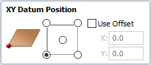
XY Drawing Origin - Here you can specify where the XY zero origin will be placed on your job. These options correspond to the same fields on the normal 'Job Setup' form within the program. Most people would use the default Bottom Left Corner, but for some jobs you may prefer to have the XY origin in the Center.
- In a job with horizontal orientation (Along X Axis), the X offset will correspond to the length of the cylinder, and the Y offset will be a point along its circumference.
- In a job with vertical orientation (Along Y Axis), it's the opposite. The Y offset will correspond to the length of the cylinder, and the X offset will be a point along its circumference.
Orientation
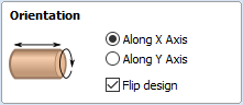
Cylinder Orientation Along - This section is used to tell the program how you have your rotary axis aligned on your machine. If you've already made your design, but just want to change the job for a different machine, then you could flip your design with the material so that all the vectors and components stay the same relative to the job.
Z Origin On - This section determines whether the Z Origin is set to the surface of the material or the base (center of cylinder). These settings can be over-ridden when the toolpath is actually saved, but we would strongly recommend the 'Cylinder Axis' is selected for rotary machining. The reasons for this are detailed in the note below.
Vector Layout
As well as creating a job at a suitable size for wrapping toolpaths, when creating the job, it will create a number of vectors which can be very useful when creating your wrapped job.
The vectors are created on their own individual layers and by default these layers are switched off to avoid cluttering up your work area. To switch on the layers, display the 'Layer Control' dialog (Ctrl+ L is the shortcut to show / hide this). To show / hide the layer simply click on the check box next to the layer name.
2Rail Sweep Rails - This layer contains two straight line vectors which can be used to sweep a profile along if you are creating a shaped column.
Bounding Box - This layer contains a rectangular vector covering the entire job area. This vector is useful if you are going to machine the complete surface of the cylinder.
Choosing stock material
When setting-up rotary project, software assumes a perfect cylinder with an exact diameter. In practice the stock material may be uneven, or only blank with square profile may be available. In those cases blank needs to be machined into cylinder of desired size, before running toolpaths associated with the actual design.
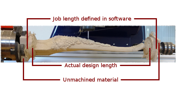
Another consideration is length of the stock material. Typically, part of the blank will be placed within the chuck. It is also important that during machining, the cutting tool is always in safe distance from both chuck and tailstock. For those reasons, the blank has to be longer than the actual design. When setting-up the machine for cutting, one has to pay extra attention to ensure that origin is set accordingly to avoid the tool running into chuck or tailstock!
If the design was created without those considerations in mind, the blank size can always be adjusted in the Job Setup form.
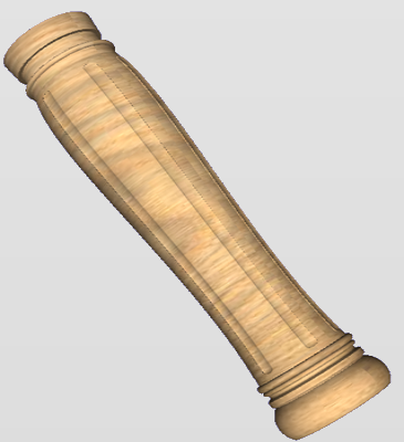
The picture below presents an example of a rotary project layout. As explained above, the actual blank is longer than job defined in Aspire to allow for the chuck and sufficient gaps. The actual design is shorter than job defined in Aspire, to leave some space for tabs, that can be machined with the profile toolpath prior to removing the finished part from the chuck.
When machining 3D shapes with varying thicknesses like on the example shown below, it is a good idea to place the thicker end of the model on the side closest to the driving motor. This way torsional twisting will mostly affect the stronger end of the machined part and help to avoid bending or breaking of the part during machining.
09. Intermediate - Simple Rotary Modelling using 2D Toolpaths
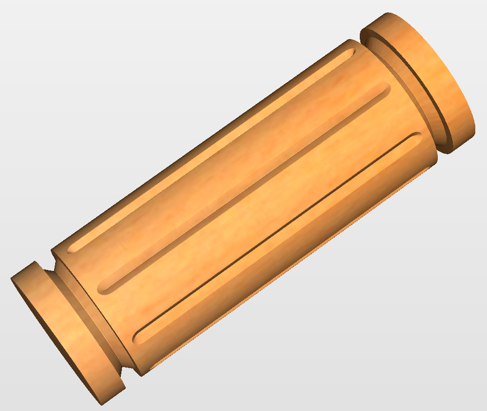
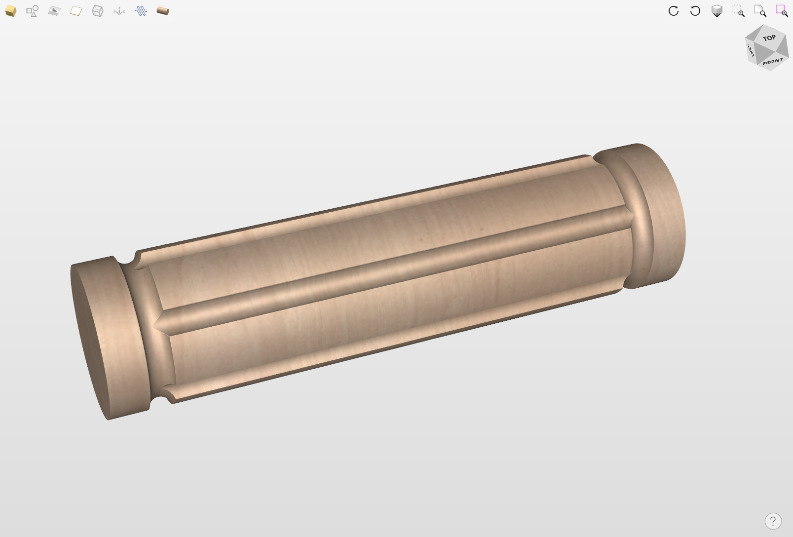
Creating vectors for a basic column
This section will show how to create a simple column, using the profile and fluting toolpaths.
Start by creating a new rotary job. Please note that settings shown here are only an example and should be adapted to match your machine setup and available material.
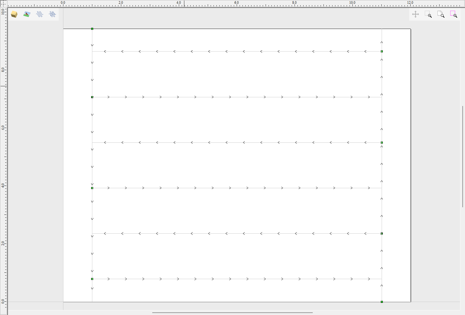
In this example the blank will rotate around X axis. We will refer to it as the rotation axis. The axis that will be wrapped is the Y axis. We will refer to it as the wrapped axis. That means that the top and bottom boundaries of the 2D workspace will actually coincide. We will refer to them as the wrapped boundaries.
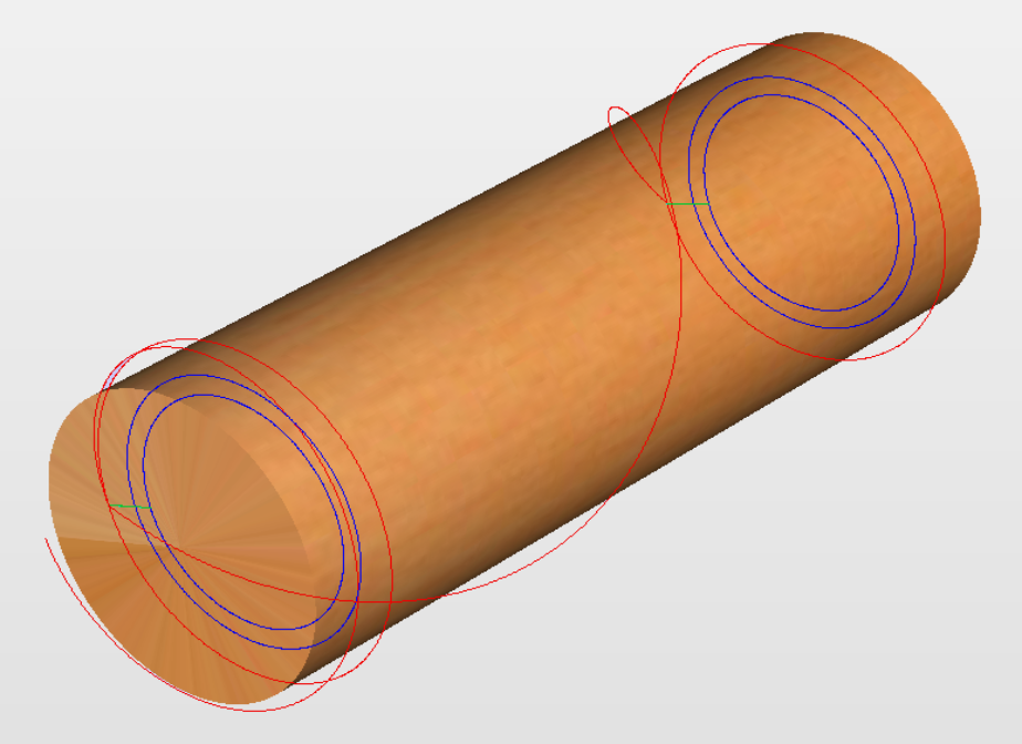
First, create the cove vectors using Draw Line/Polyline tool. Those will run along the wrapped axis at both ends of the design. Snapping may be useful to ensure that the created line starts and ends at the wrapped boundaries.
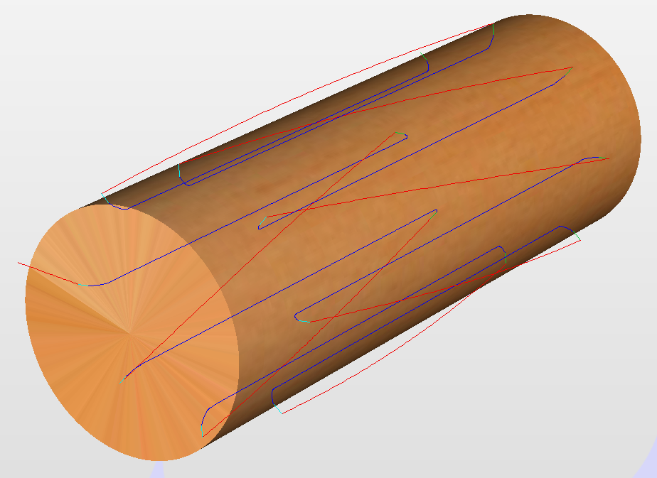
In this example the coves were placed 1 inch from the job boundaries, leaving 10 inches in the middle for the flutes. The flutes will run along rotation axis. Assuming 0.5 inch gap between the cove and the beginning of the flute, the flutes will have the length of 9 inches. This example will use 8 flutes.
To start, create a line parallel to rotation axis that is 9 inches long. Now select the created flute vector and then select one of the cove vectors while holding down Shift. Then use Copy Along Vectors tool to create 9 copies. The original flute vector may now be removed as it is no longer necessary. Note that first and last copy are both created on wrapped boundaries. That means they will coincide, so one of them can be removed. As the last step select all flute vectors and press F9 to place them in the center of design.
Creating rotary toolpaths
The process of creating 2D rotary toolpaths is very similar to creating toolpaths for Single - and Double - models. This example will use the profile toolpath on the cove vectors. To create the toolpath, select the cove vectors and click on the Profile Toolpath from
To create the toolpath for the flutes, select the flute vectors and click on the Fluting Toolpath. This Example used a 1 inch 90deg V-Bit set to Flute Depth 0.2 and using the Ramp at Start and End and Ramp Type Smooth options. Ramp length was set to 0.25 inches. Both toolpaths can be seen below.
Simulating and saving toolpaths
It is time to simulate toolpaths using Preview Toolpaths. If the option to animate the preview is selected, the simulation will be visualized in flat mode. Once the simulation is complete, the wrapped rotary view will be turned back on automatically.
Contrary to single - and double - sided simulation, rotary simulation is not 100% accurate. For example round holes will appear in rotary view as oval ones, but obviously will be round when part is actually machined.
Although the design can be considered to be finished, in practice it is useful to be able to cut-out the remaining stock. This can be realized by making the design slightly longer and adding profile cuts. In this example the blank length was extended by 2 inches using the Job Setup . Existing vectors can be recentered using F9After that the existing toolpaths have to be recalculated.
The cut-out vectors can be created in the same way as cove vectors. Two extra profiling toolpaths can be created using the suitable End Mill. In this example we used a tab with a 0.5 inch diameter. In order to achieve that, the user can type the following in the Cut Depth box: z-0.25 and then press = and the software will substitute the result of the calculation. Variable 'z' used in the formula will be substituted by the radius of the blank automatically by software. It is also important to specify Machine Vectors Outside/Right or Machine Vectors Inside/Left as appropriate. The cut-out toolpaths and the resulting simulation can been shown below.
The final step is to save the toolpaths in a format acceptable by your machine. Use the Save Toolpaths and select the wrapped post-processor matching your machine.
Note
Tools and values presented in this example are for illustrative purposes only. Size of tools, feed rate, tabs diameter etc. have to be adapted to the material and machine used to ensure safe and accurate machining.
Spiral toolpaths
This section will explain how to create and simulate spiral toolpaths.
One way of thinking about spiral toolpaths is to imagine a long, narrow strip of fabric. Such a strip can be wrapped around a roll at a certain angle. In order to create a toolpath that wraps around the blank multiple times, one can create a long vector at a certain angle. Such a vector is an equivalent to the strip of fabric when it is unwrapped from the roll.
Although such a toolpath will exceed the 2D workspace of the rotary job, thanks to the wrapping process during both simulation and machining the toolpath will actually stay within material boundaries.
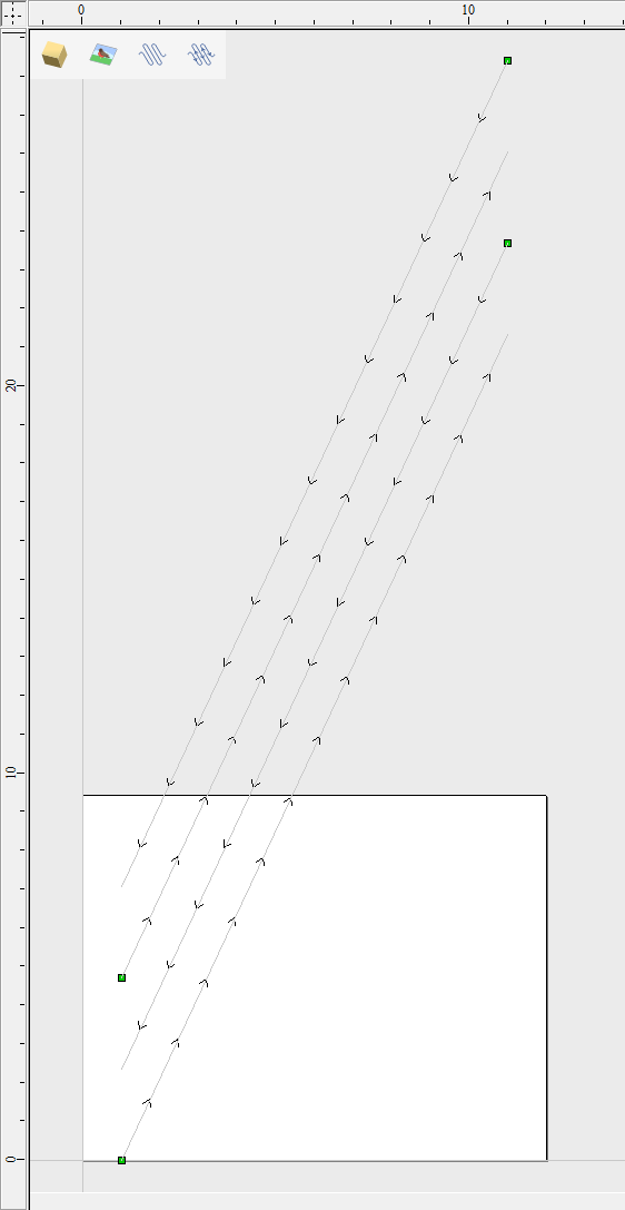
The most crucial part of designing spiral vectors is to determine the right angle and length of the line that would result in a given number of wraps. Suppose one would like to modify a simple column design to use spiral flutes, rather than parallel to rotation axis. The following example will use flutes wrapping 3 times each, but the method can be adapted to any other number.
All but one of the existing flute vectors can be removed. Select the Draw Line/Polyline and start a new line by clicking at one end of the existing flute. This line needs to be made along the wrapped axis with the length being 3 times the circumference of the job. In this example that means typing 90 into the Angle box and typing y * 3 into the Length box and pressing =. If the wrapped axis is not the Y axis, but rather the X axis, then the above formula should be x * 3.
Now one can simply draw a line connecting to the other end of the original flute vector and the newly created one. Using Copy Along Vectors tool this single flute may be copied in the way described earlier. In this example 4 spiral flutes were created, as can be seen below.
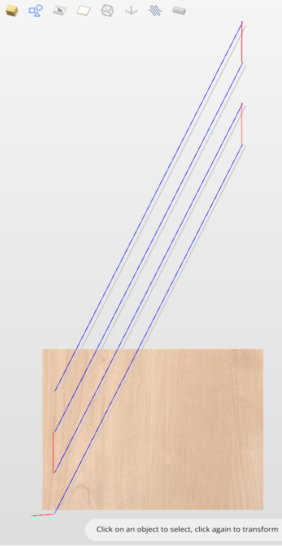
Once the flute vectors are ready, the toolpath can be created again using the Fluting Toolpath. An important thing to note, is the difference between the appearance of spiral toolpaths in the wrapped and flat view. By clicking on Auto Wrapping one can switch from wrapped rotary view to flat view and back again.
As can be seen above, in the flat view the toolpaths will follow the vectors and extend beyond the job boundaries. On the other hand the wrapped view, presented below, will display the toolpaths spiralling around the blank.
This was just a brief overview of general 2D workflow for rotary machining. Remember to also take a look at video tutorials dedicated to rotary machining, which are accessible from the Tutorial Video Browser link when the application first starts.
10. Advanced - Rotary Machining and Wrapping
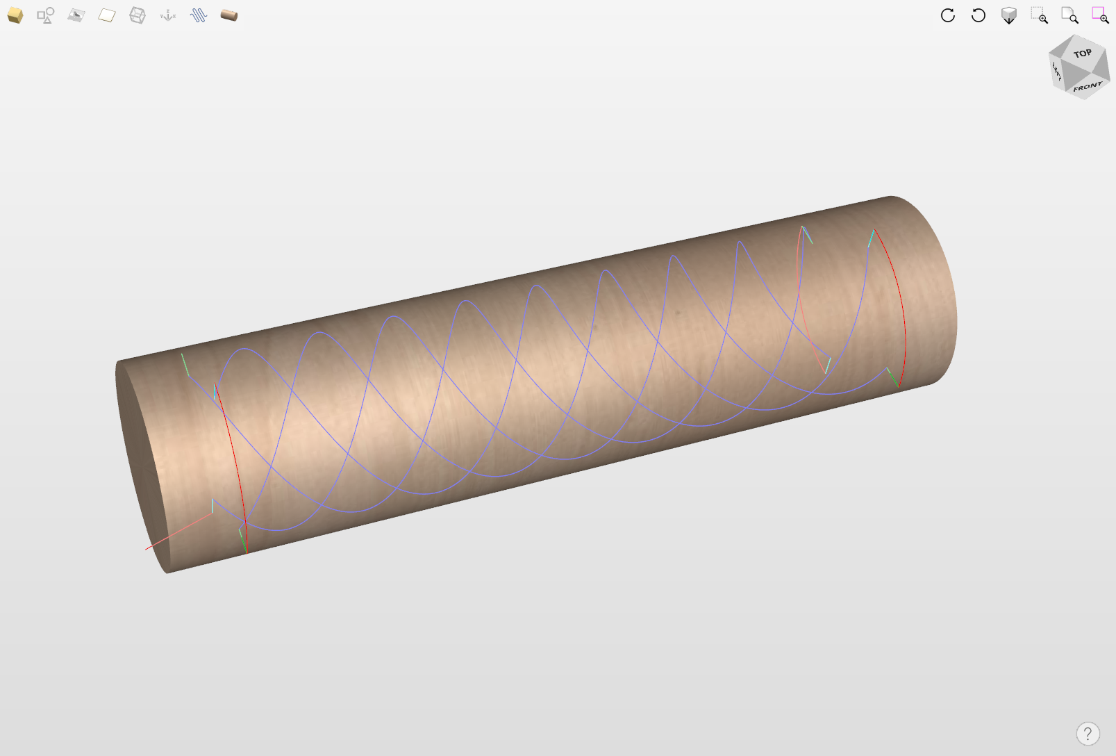
Cut2D Desktop can 'wrap' flat toolpaths around a cylinder to provide output to CNC machines which are configured with a rotary axis / indexer. The image below shows a flat toolpath wrapped around part of a cylinder.
Note
It is important to note that wrapping works in conjunction with specially configured post-processors which take the XYZ 'flat' toolpaths and wrap them around a rotary axis, replacing either the X or Y moves with angular moves.
The toolpaths can be visualized wrapped within the program when the Auto Wrapping mode is on.
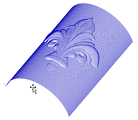
Cut2D Desktop can also visualize a wrapped model within the program by drawing the shaded composite model wrapped.
Cut2D Desktop also has the ability to draw the toolpath simulation wrapped. Although this is very useful for getting a feel for how the finished product will look, it is important to realize that the wrapped simulation may not be a 100% accurate representation of how the finished product will look. An example of potential difference would be if you drilled holes in your rotary job. In the actual work piece these will obviously just be round holes, in the wrapped simulation these may appear as distorted ovals due to the 'stretching' process which takes place when we wrap the flat simulation model for display.
Note
If your rotary axis is aligned along your Y axis you would choose the Orientation Along Y Axis option during job setup. All the examples in this document will assume that the rotary axis is aligned along X.
It is important to realize that there are a huge number of possible combinations of machine controller and axis orientations for rotary axis / indexers. This means it is impractical for Vectric to supply a pre-configured post-processor for every possible combination as standard. We include some wrapping post-processors in the software that can be configured when you setup your Machine Configuration.
If you need to select a new post, you can do so by accessing the Save Toolpaths menu. To do so, click the 'Manage machine configuration' button as seen in the image below:
This will now open a menu where you can press the button under 'Associated Post-Processors' to access all of the available post-processors within the software and choose the appropriate wrapped post-processor for your machine configuration.
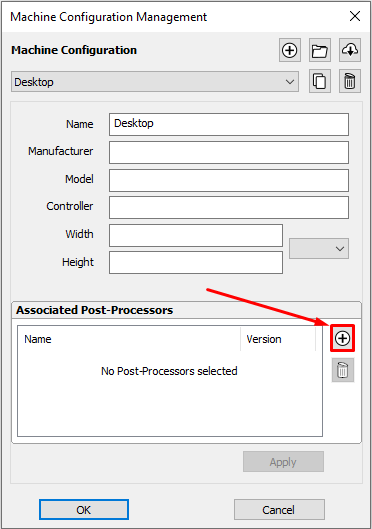
You can also right click the post in this menu and select 'view' to view the contents of the post, should you need to edit it later.
Examining these posts may be helpful if you need to configure a post of your own. If Vectric have not supplied a standard a post for your machine configuration please refer to the Post Processor Editing Guide accessible from the Help menu of the program for information on how to configure a post-processor and also look at the standard rotary posts Vectric supply.
You should also look at the Vectric forum to see if anyone else has already configured a post for your configuration or one similar. If, after looking at these resources you are still unsure of what needs to be done for your machine, please feel free to contact support@vectric.com for help. However, please note that we cannot guarantee to write a custom rotary post-processor for every individual requirement.
15. Advanced - Post-Processor Editing
What does the Post Processor Do?
The post processor is the section of the program that converts the XYZ coordinates for the tool moves into a format that is suitable for a particular router or machine tool. This document details how to create and edit the configuration files that customize the output from the program to suit a particular machine control.
Below are sections of a typical program that has been post processed into both G-Code and HPGL
G-Code Output
T1 M6
G17
G0 Z4.5000
G0 X0.0000 Y0.0000 S12000 M3
G0 X2.4567 Y7.8342 Z0.2500
G1 Z-0.0500 F5.0
G3 X3.3784 Y8.7559 I0.0000 J0.9218 F66.0
G3 X2.4567 Y9.6777 I-0.9218 J0.0000
G3 X1.5349 Y8.7559 I0.0000 J-0.9218
HPGL Output
IN;PA;
PU2496,7960;
PD2496,7960;
AA2496,8896,90.000
AA2496,8896,90.000
AA2496,8896,90.000
AA2496,8896,90.000
PU2496,7960;
PU2496,6096;
Machine controller manufacturers will often customize the file format required for programs to run on a particular machine in order to optimize the control to suit the individual characteristics of that machine.
The Vectric post processor uses simple text based configuration files, to enable the user to tailor a configuration file, should they wish to do so.
Post Processor Sections
Vectric post processors are broken down into sections to aid clarity, try to write your post processors in a similar style to aid debugging.
File Comments
A section where you can describe the post processor and record any changes to the post processor, each line is a comment and starts with a ‘+’ character or a ‘|’ character.
+ History
+ Who When What
+ ======== ========== ===========================
+ Tony 14/07/2006 Written
+ Mark 26/08/2008 Combined ATC commands, stop spindle on TC
+================================================
Global File Statements
Statements are items that are either used only once, or have static values throughout the file. Write statement names in upper case letters for clarity.
Statement | Result |
|---|---|
| The name that will appear in the post processor list |
| The file extension that the file will be given |
| The units that the file outputs (INCHES or MM) |
| The machine tool manufacturer has supplied a driver (usually a printer driver) thatn can directly accept the NC file output (For example see Generic HPCL_Arcs.pp) |
| Indicates that plunge moves to Plunge (Z2) height (that is set on the material setup form) are rapid moves |
| The control software uses a document interface that can directly accept the NC file output. |
| The moves in the Y axis are to be wrapped around a cylinder of the specified diameter. The "Y" values will be output as "A" |
| The moves in the X axis are to be wrapped around a cylinder of the specified diameter. The "X" values will be output as "B" |
| Spindle speed for this machine is output as a range of integer numbers between 1 and 15 representing the actual speed in RPM of the spindle, (between 4500 and 15000 RPM in the quoted example). For an example, see the file: Roland_MDX-40_mm.pp |
| This command allows you to substitute a character output within the variables (such as The characters are entered in pairs, Original - Subsititued. For example MACH 3 control software uses parentheses as comment delimiters, and does not allow nested comments. Most tools within the Vectric Tool Database have parentheses within the “Name” section; if these names are output, this would cause an error within Mach3. The command |
| Rotary: Enables / Disables output of the feedrate F in Inverse Time Feed Mode. In this mode, we're expected to complete a move in one divided by the F number of minutes. In GCode, this would usually be a G93 to switch on Inverse Time Mode, or a G94 to set Units per Minutes mode. |
| Indicates that this post-processor supports laser toolpaths (if the Laser Module is installed). |
| Optional minimum arc radius. Arcs which have a radius smaller than this value will be replaced with a single straight line move. |
| Optional maximum arc radius. Arcs which have a radius greater than this value will be polygonized. |
POST_BASE | This is a no longer supported way of inheriting the content of another post-processor. See the POST_BASE Migration page for more details. |
Tape Splitting Support
A section that describes how a long toolpath output will be split:
TAPE_SPLITTING=MAX_NUM_LINES LINE_TOL "FILENAME_FORMAT" START_INDEX INDEX_ON_FIRST_FILE
For example a command of:
TAPE_SPLITTING=1000 100 "%s_%d.tap" 1 "YES"
would lead to...
Output will be split into multiple files of a maximum of 1000 lines (+ however many lines in there are within the footer section of the post processor), if a retract move exists after line 900 (1000 – 100), the file will be split at that move. If the file was called "toolpath" the split files would be named toolpath_1.tap, toolpath_2.tap etc. The first toolpath output will be "toolpath_ 1.tap" there will be no file named "toolpath" without an index number, (as INDEX_ON_FIRST_FILE=YES is used), unless the file was less than 1000 lines long, in which case the file would not be split.
Note
Some controllers that require NC files to be split, also have limitations on the number of characters within a filename. For example they may require the file to be named with the MSDOS style 8.3 filename format. This should be considered when naming the output file.
Line Terminating Characters
LINE_ENDING="[13][12]"
Decimal values of the characters appended to each separate line of the post processed file. (Will usually be [13][10]) (Carriage return, line feed) for any controller that can read a windows or MSDOS format text file.
Block Numbering
If you wish to add line numbers to the output file, the current line number is added with the variable [N]. The behaviour of this line number variable is controlled by the following variables:
Statement | Result |
|---|---|
| Value at which the line numbering should start |
| Incremental value between line numbers |
| The maximum line number to output, before cycling to the Important - Some controllers have a limit to the number of lines that can be displayed on the control |
Variables
Variable Name | Output using | Value | Example File |
|---|---|---|---|
|
| Current Feed Rate. | Mach2_3_ATC_Arcs_inch.pp |
|
| Current Cut Feed Rate. | CNCShark-USB_Arcs_inch.pp |
|
| Current Plunge Feed Rate. | CNCShark-USB_Arcs_inch.pp |
|
| Current Spindle Speed in R.P.M. | GCode_arc_inch.pp |
|
| Current power setting for jet-based tools (e.g. lasers) | grbl_mm.pp |
|
| Current Tool Number. | Mach2_3_ATC_Arcs_inch.pp |
|
| Previous Tool Number. | NC-Easy.pp |
|
| Line Number. | Mach2_3_ATC_Arcs_inch.pp |
|
| Name of Current Tool. | MaxNC_inch.pp |
|
| Text from Note field in ToolDB for current tool | Busellato_Jet3006_arc_inch.pp |
|
| Name of Current Toolpath. | Viccam_ATC_Arcs_inch.pp |
|
| Filename (Produced by “Save Toolpath(s)”). | ez-Router_inch.pp |
|
| Folder Toolpath File was saved to. | Woodp_arc_mm.pp |
|
| Toolpath File Extension. | TekcelE_Arc_ATC_3D.pp |
|
| Toolpath Folder Pathname. | WinPC-NC_ATC_Arcs_mm.pp |
|
| Current coordinate of tool position in X axis. | GCode_arc_inch.pp |
|
| Current coordinate of tool position in Y axis. | GCode_arc_inch.pp |
|
| Current coordinate of tool position in Z axis. | GCode_arc_inch.pp |
|
| Current coordinate of tool position in A axis. | |
|
| Arc centre in X Axis (relative to last X,Y position). | Mach2_3_ATC_Arcs_inch.pp |
|
| Arc centre in Y Axis (relative to last X,Y position). | Mach2_3_ATC_Arcs_inch.pp |
|
| Arc centre in X Axis (absolute coordinates). | Isel_arc_mm.pp |
|
| Arc centre in Y Axis (absolute coordinates). | Isel_arc_mm.pp |
|
| Start position of an arc in X axis. | TextOutput_Arcs_mm.pp |
|
| Start position of an arc in Y axis. | TextOutput_Arcs_mm.pp |
|
| Mid-point of arc in X (absolute coordinates). | TextOutput_Arcs_mm.pp |
|
| Mid-point of arc in Y (absolute coordinates). | TextOutput_Arcs_mm.pp |
|
| Mid-point of arc in X (incremental coordinates). | TextOutput_Arcs_mm.pp |
|
| Mid-point of arc in Y (incremental coordinates). | TextOutput_Arcs_mm.pp |
|
| The radius of an arc. | Bosch_ATC_Arcs_mm.pp |
|
| The angle of an arc. | Generic HPGL_Arcs.pp |
|
| Home tool position for X axis. | CAMTech_CMC3_mm.pp |
|
| Home tool position for Y axis. | CAMTech_CMC3_mm.pp |
|
| Home tool position for Z axis. | CAMTech_CMC3_mm.pp |
|
| Safe Z Height / Rapid Clearance Gap. | EMC2 Arcs(inch)(*.ngc) |
|
| Diameter of cylinder that axis is wrapped around. | Mach2_3_WrapY2A_ATC_Arcs_mm.pp |
|
| Length of material in X. | Mach2_3_ATC_Arcs_inch.pp |
|
| Length of material in Y. | Mach2_3_ATC_Arcs_inch.pp |
|
| Length of material in Z. | Mach2_3_ATC_Arcs_inch.pp |
|
| Minimum value of material in X. | MaxNC_inch.pp |
|
| Minimum value of material in Y. | MaxNC_inch.pp |
|
| Minimum value of material in Z. | MaxNC_inch.pp |
|
| Maximum value of material in X. | MaxNC_inch.pp |
|
| Maximum value of material in Y. | MaxNC_inch.pp |
|
| Maximum value of material in Z. | MaxNC_inch.pp |
|
| Origin Position in X. | TextOutput_Arcs_mm.pp |
|
| Origin Position in Y. | TextOutput_Arcs_mm.pp |
|
| Z Zero Position, Table or Material Surface. | TextOutput_Arcs_mm.pp |
|
| X, Y Origin. | TextOutput_Arcs_mm.pp |
|
| List of tools used (In order of use). | Mach2_3_ATC_Arcs_inch.pp |
|
| List of toolpaths used in file (in order of use). | Mach2_3_ATC_Arcs_inch.pp |
|
| Toolpath Notes (Toolpath Control form). | Mach2_3_ATC_Arcs_inch.pp |
|
| File Notes (Edit > Notes). | Mach2_3_ATC_Arcs_inch.pp |
|
| File creation time. | Mach2_3_ATC_Arcs_inch.pp |
|
| File creation date. | Mach2_3_ATC_Arcs_inch.pp |
|
| Dwell time in seconds when drilling. | Mach2_3_Arcs_inch.pp |
|
| Name of the product used to output file, including version number. | |
|
| Tool diameter. | |
|
| Rotary: Current Inverse Time Rate | AvidCNC_WrapX2A_G93_inch.pp |
Format of Variables
Values for tool position, feed rates, spindle speeds etc. are inserted into the file using variables. Variables are used throughout the file; the variables are replaced with the current value for that item when the file is post processed. For example, the current X, Y and Z tool positions at any time, are inserted into the file by using the variable output, [X], [Y] and [Z] respectively.
Write variable names in upper case letters for clarity.
A Variable is formatted as follows:
VAR VARIABLE = [VO|WO|CS|VF|MX]
where
VO= Variable output for example X, XF or F.WO= When output, A=Always, C=Only when changed.CS= Character string output before value .VF= Value format, determines the format that the value is output with.MX= Multiplier Value.
A typical variable
1 | 2 | 3 | 4 | 5 | 6 | 7 | 8 | 9 | 10 | 11 | 12 | 13 | 14 | 15 |
|---|---|---|---|---|---|---|---|---|---|---|---|---|---|---|
|
|
|
|
|
|
|
|
|
|
|
|
|
|
|
VAR- This line is a Variable.- Variable Name.
- Equals Sign.
- Open Square bracket - (start of variable formatting parameters).
- Variable label - i.e. label that is substituted with the variable value.
- Vertical Bar - Parameter separator.
A= Always output value,C= Only output value when it changes- Vertical Bar - Parameter separator.
- Character string to print before variable value.
- Vertical Bar - Parameter separator.
- Optional Format Flags - for details see below.
- Value Format - units and number of decimal places to output.
- Vertical Bar - Parameter separator.
- Output multiplier - for details see below.
- Close Square Bracket - End of formatting parameters.
Formatting the Output Value
The values format string should be formatted as follows:
FORMAT_FLAGS FIELD_WIDTH DECIMAL_SEPARATOR DECIMAL_PLACES
The format flags are optional and only needed by a small number of controllers they will be described shortly.
Field Width The Field width represents the minimum number of characters that are output. The field width is usually set to “1” a value greater than 1 is typically only required if a controller expects to see a fixed number of characters for the value. If this is the case, a number greater than 1 can be entered. The number entered will ensure that that number of characters is output. The number that represents the field width includes the full floating-point number for the output value, (including the decimal separator character).
Decimal Separator The decimal separator character is almost always just a period character, but there are some controllers that expect to see a comma character. (For an example of a post processor that does not use a period character, see the file: Heidenhain_inch.pp)
Decimal Places The number of decimal places output following the decimal separator. The values are often set at 3 for controllers operating in Metric, or 4 for controllers operating in Inches.
Optional Format Flags
The output values can be further modified by using the optional format flags:
Flag | Function | Default (without flag) |
|---|---|---|
| Left Justify the output | Values are right justified |
| Prefix the value with '+' or '-' | Only negative values are prefixed |
| If value has fewer characters than the set minimum, the value is prefixed with zeroes | Values is prefixed with blanks spaces |
| Values is always output with a separator character ( in practice this would only change the output value if the value is set to output integer values only) | When output is set to integer only, separator charactor is not appended to value. |
Default Formatting For Variables
Most variables have a default format; (shown below) to set a different format for a variable, enter the line below in your post processor and alter the parameters to suit your controller.
Default | Example |
|---|---|
|
The line number will always be output. An 'N' character will be inserted before the line number. It will be output as an integer number |
|
The spindle speed will always be output. An 'S' character will be inserted before the value and it will be output as an integer number. |
|
The feed rate will be output with an F character before the value, and will only be output when it changes. The value will be output to 1 decimal place Note In this format string there is an option extra parameter. This is the value multiplier. |
VAR PLUNGE_RATE = [FP|A||1.0] |
The plunge rate will be output with an F character before the value, and will only be output when it changes. The value will be output to 1 decimal place. Note In this format string there is an option extra parameter. This is the value multiplier. |
|
The cut rate will be output with an F character before the value, and will only be output when it changes. The value will be output to 1 decimal place. Note In this format string there is an option extra parameter. This is the value multiplier. |
|
The position value will be output with an ‘X’ character before the value, the position will Always be output, and will be output to 3 decimal places, this would typically be suitable for a control that requires metric output. If you wished to output the values to 4 decimal places as would be more typical for a controller operating in inches. You would format the line as follows.
|
|
The home position value will be output with an ‘X’ character before the value, the position will Always be output, and will be output to 3 decimal places, this would typically be suitable for a control that requires metric output. If you wished to output the values to 4 decimal places as would be more typical for a controller operating in inches. You would format the line as follows.
|
|
The value will be output with an ‘X’ character before the value, the position will Always be output, and will be output to 3 decimal places, this would typically be suitable for a control that requires metric output. If you wished to output the values to 4 decimal places as would be more typical for a controller operating in inches. You would format the line as follows.
Note In this format string there is an option extra parameter. This is the value multiplier. |
|
The value will be output with an ‘Y’ character before the value, the value will Always be output, and will be output to 3 decimal places, this would typically be suitable for a control that requires metric output. If you wished to output the values to 4 decimal places as would be more typical for a controller operating in inches. You would format the line as follows.
|
|
The value will be output with a ‘J’ character before the value, the value will Always be output, and will be output to 3 decimal places, this would typically be suitable for a control that requires metric output. If you wished to output the values to 4 decimal places as would be more typical for a controller operating in inches. You would format the line as follows.
|
|
The value will be output with a ‘J’ character before the value, the value will Always be output, and will be output to 3 decimal places, this would typically be suitable for a control that requires metric output. If you wished to output the values to 4 decimal places as would be more typical for a controller operating in inches. You would format the line as follows.
Note In this format string there is an option extra parameter. This is the value multiplier. |
|
The value will be output with a ‘X’ character before the value, the value will Always be output, and will be output to 3 decimal places, this would typically be suitable for a control that requires metric output. If you wished to output the values to 4 decimal places as would be more typical for a controller operating in inches. You would format the line as follows.
|
|
The value will be output with a ‘R’ character before the value, the value will Always be output, and will be output to 3 decimal places, this would typically be suitable for a control that requires metric output. If you wished to output the values to 4 decimal places as would be more typical for a controller operating in inches. You would format the line as follows.
|
|
The value will be output with a ‘A’ character before the value, the value will Always be output, and will be output to 3 decimal places, this would typically be suitable for a control that requires metric output. If you wished to output the values to 4 decimal places as would be more typical for a controller operating in inches. You would format the line as follows.
|
|
The value will be output with an ‘X’ character before the value, the value will Always be output, and will be output to 3 decimal places. |
Multiplier Value
The multiplier value is used to multiply the value to output a different value. Common reasons for wishing to do this are:
To convert the default output of an Inch post processor, from inches per minute to inches per second, (Multiply by 0.01666).
To convert the default output of a Metric post processor, from mm per minute to mm per second, (Multiply by 0.0166).
To make positive values negative (and vice versa), (Multiply by -1).
To convert the output of an arc angle from radians to degrees, (Multiply by 57.2957795).
To multiply or divide by a fixed factor (I.E. produce 1:4 scale model, Multiply by 0.25)
Post Processor Blocks
HEADER
+---------------------------------------------------
+ Commands output at the start of the file
+---------------------------------------------------
begin HEADER
"Commands"
The header is the location for the instructions that are output once, at the start of the file, these generally setup modal commands for the controller.
For example, the Header might contain a command to display the filename on the controller and a series of “G-Codes” to set the machine up, for instance G20 to tell the control that the moves are in inches, or G21 to tell the control that the moves are in millimetres.
Variables that you might wish to be within the header section, could include:
Information about the Material Block
- Minimum extent in X = [XMIN]
- Minimum extent in Y = [YMIN]
- Minimum extent in Z = [ZMIN]
- Maximum extent in X = [XMAX]
- Maximum extent in Y = [YMAX]
- Maximum extent in Z = [ZMAX]
- Length of material in X = [XLENGTH]"
- Length of material in Y = [YLENGTH]"
- Depth of material in Z = [ZLENGTH]"
Home Position Information
- Home X = [XH]
- Home Y = [YH]
- Home Z = [ZH]
- Rapid clearance gap or Safe Z = [SAFEZ]
Details of the first tool to be used.
- Tool Number = [T]
- Tool name = [TOOLNAME]
Initial cutting speeds
- Feed Rate used for cutting and plunging into the material = [F]
- Feed Rate whilst tool is Cutting the material = [FC]
- Feed Rate whilst tool is plunging into the material = [FP]
Actual values depend on the UNITS set (see Global File Settings) Defaults are either MM/Minute or Inches/Minute, but the output can be changed to suit by setting the appropriate “VAR FEED_RATE” formatting.
Spindle Speed
- Spindle Speed = [S] R.P.M.
SPINDLE_ON
+---------------------------------------------------
+ Commands output at when the Spindle first turns on.
+---------------------------------------------------
begin SPINDLE_ON
"Commands"
The Spindle On section was added to allow for Spindle and Laser operations in the same Post Processor instead of having the Spindle on command as part of the header.
Typically this will just have the Spindle on command (M03 for example) but can also include a Spindle speed command [S]
TOOLCHANGE
+---------------------------------------------------
+ Commands output at toolchange
+---------------------------------------------------
begin TOOLCHANGE
"Commands"
Commands that are output when a change of tool is required. Variables and commands that might be used include:
- Previous Tool Number = [TP]
- Tool Number = [T]
- Tool name = [TOOLNAME]
- Toolpath Name = [TOOLPATH_NAME]
- Toolpath Pathname = [PATHNAME]
- Toolpath File Name = [TP_FILENAME]
- Toolpath File Directory = [TP_DIR]
- Toolpath Extension = [TP_EXT]
- Spindle Speed = [S] R.P.M.
- M3 M Code often used to turn spindle on (Clockwise rotation).
- M5 M Code often used to turn spindle off.
NEW_SEGMENT
+---------------------------------------------------
+ Commands output for a new segment ( new toolpath with current toolnumber)
+---------------------------------------------------
begin NEW_SEGMENT
"Commands"
For an example of a NEW_SEGMENT section, see the file: Mach2_3_ATC_Arcs_inch.pp
Commands that are output when a new toolpath uses the currently selected tool, but perhaps a different spindle speed is required or the machine requires additional instructions.
Any commands that are used in the NEW_SEGMENT section should not need to be included within the TOOLCHANGE section as a tool-change will also automatically call the instructions in the NEW_SEGMENT section.
Variables that are commonly used include.
- Spindle Speed = [S] R.P.M.
- M3 M Code often used to turn spindle on (Clockwise rotation).
- M5 M Code often used to turn spindle off.
INITIAL_RAPID_MOVE
+---------------------------------------------------
+ Commands output for Initial rapid move
+---------------------------------------------------
begin INITIAL_RAPID_MOVE
"Commands"
For an example of a INITIAL_RAPID_MOVE section, see the file: Saom_OSAI_Arc_inch.pp
Commands that are output when the very first rapid move is made following the header or a tool change. A Section not used for most posts, but useful if the very first rapid move, needs to output different information to subsequent rapid moves. This section is sometimes required for HPGL variants.
RAPID_MOVE
+---------------------------------------------------
+ Commands output for rapid moves.
+---------------------------------------------------
begin RAPID_MOVE
"Commands"
Commands that are output when rapid moves are required.
FIRST_FEED_MOVE
+---------------------------------------------------
+ Commands output for first feed rate move in a series of feed moves.
+---------------------------------------------------
begin FIRST_FEED_MOVE
"Commands"
This section is commonly used where controllers require that the Feed Rate is set at the first feed move, this rate would then be used for subsequent cut moves.
For an example of a FIRST_FEED_MOVE section, see the file: Axyz_Arcs_ATC_inch.pp
FEED_MOVE
+---------------------------------------------------
+ Commands output for feed rate moves
+---------------------------------------------------
begin FEED_MOVE
"Commands"
Used to output information required at every move, or all feed moves except for the First Feed Move, if a FIRST_FEED_MOVE section is present within the post processor.
FIRST_CW_ARC_MOVE
+---------------------------------------------------
+ Commands output for the first clockwise arc move in a series of cw arc moves
+---------------------------------------------------
begin FIRST_CW_ARC_MOVE
"Commands"
Similar to the FIRST_FEED_MOVE section, but for clockwise arc segments. This section is commonly used where controllers require that the Feed Rate is set for the first arc segment, this rate would then be used for subsequent arc moves in the same direction.
For an example of a FIRST_CW_ARC_MOVE section, see the file: Centroid_Arcs_inch.pp
FIRST_CW_HELICAL_ARC_PLUNGE_MOVE
+---------------------------------------------------
+ Commands output for clockwise helical arc plunge move in a series of moves.
+---------------------------------------------------
begin FIRST_CW _HELICAL_ARC_MOVE
"Commands"
Similar to the FIRST_CW_ARC_MOVE section, but for moves that also move in Z. Feed rates output are from Plunge rate set for the tool.
For an example of a CW_HELICAL_ARC_PLUNGE_MOVE section, see the file: Mach2_3_ATC_Arcs_inch.pp
FIRST_CW_HELICAL_ARC_MOVE
+---------------------------------------------------
+ Commands output for clockwise helical arc move in a series of moves.
+---------------------------------------------------
begin FIRST_CW_HELICAL_ARC_MOVE
"Commands"
Similar to the FIRST_CW_ARC_MOVE section, but for moves that also move in Z.
For an example of a CW_HELICAL_ARC_MOVE section, see the file: Mach2_3_ATC_Arcs_inch.pp
CW_ARC_MOVE
+---------------------------------------------------
+ Commands output for clockwise arc moves.
+---------------------------------------------------
begin CW_ARC_MOVE
"Commands"
Similar to the FEED_MOVE section, but for clockwise arc segments.
For an example of a CW_ARC_MOVE section, see the file: Centroid_Arcs_inch.pp
CW_HELICAL_ARC_MOVE
+---------------------------------------------------
+ Commands output for clockwise helical arc moves
+---------------------------------------------------
begin CW_HELICAL_ARC_MOVE
"Commands"
Similar to the CW_ARC_MOVE section, but for moves that also move in Z.
For an example of a CW_HELICAL_ARC_MOVE section, see the file: Mach2_3_ATC_Arcs_inch.pp
FIRST_CCW_ARC_MOVE
+---------------------------------------------------
+ Commands output for the first counter-clockwise arc move in a series of ccw arc moves.
+---------------------------------------------------
begin FIRST_CCW_ARC_MOVE
"Commands"
Similar to the FIRST_FEED_MOVE section, but for counter-clockwise arc segments. This section is commonly used where controllers require that the Feed Rate is set for the first arc segment, this rate would then be used for subsequent arc moves in the same direction.
For an example of a FIRST_CCW_ARC_MOVE section, see the file: Centroid_Arcs_inch.pp
FIRST_CCW_HELICAL_ARC_PLUNGE_MOVE
+---------------------------------------------------
+ Commands output for counter- clockwise helical arc plunge move in a series of moves.
+---------------------------------------------------
begin FIRST_CCW_HELICAL_ARC_MOVE
"Commands"
Similar to the FIRST_CCW_ARC_MOVE section, but for moves that also move in Z. Feed rates output are from Plunge rate set for the tool.
For an example of a CCW_HELICAL_ARC_PLUNGE_MOVE section, see the file: Mach2_3_ATC_Arcs_inch.pp
FIRST_CCW_HELICAL_ARC_MOVE
+---------------------------------------------------
+ Commands output for first counter-clockwise helical arc move in a series of moves.
+---------------------------------------------------
begin FIRST_CCW_HELICAL_ARC_MOVE
"Commands"
Similar to the FIRST_CCW_ARC_MOVE section, but for moves that also move in Z.
For an example of a CCW_HELICAL_ARC_MOVE section, see the file: Mach2_3_ATC_Arcs_inch
CCW_ARC_MOVE
+---------------------------------------------------
+ Commands output for counter-clockwise arc moves.
+---------------------------------------------------
begin CCW_ARC_MOVE
"Commands"
Similar to the FEED_MOVE section, but for counter-clockwise arc segments.
For an example of a CCW_ARC_MOVE section, see the file: Centroid_Arcs_inch.pp
CCW_HELICAL_ARC_MOVE
+---------------------------------------------------
+ Commands output for counter-clockwise helical arc moves
+---------------------------------------------------
begin CCW_HELICAL_ARC_MOVE
"Commands"
Similar to the CCW_ARC_MOVE section, but for moves that also move in Z.
For an example of a CCW_HELICAL_ARC_MOVE section, see the file: Mach2_3_ATC_Arcs_inch.pp
FOOTER
The footer is the section of the post processor for instructions that are sent to the controller at the end of a file. These might be instructions to return the tool to the home position, switch the spindle off or switch the power off to the drives.
+---------------------------------------------------
+ Commands output at the end of the file
+---------------------------------------------------
begin FOOTER
"Commands"
Variables that are commonly used include.
- G00 [XH] [YH] [ZH] Rapid to X,Y,Z Home position.
- M05 M Code often used to turn spindle off.
- M30 M Code often used to signify the end of the file.
SPINDLE_ON
The Spindle On section is used after the Header and allows the Spindle on commands to be used in a combination Milling/Laser Post Processor.
If Spindle on commands are used in the Header, this Block should not be included.
+---------------------------------------------------
+ Commands output at the end of the file
+---------------------------------------------------
begin SPINDLE_ON
"Commands"
Variables that are commonly used include.
- M3 for Spindle On
- [S] For Spindle Speed
Jet Support Sections
These sections are for supporting jet-based cutting tools such as lasers, plasmas and waterjets.
JET_TOOL_POWER
+---------------------------------------------------
+ Commands output when the cutter's power is set
+---------------------------------------------------
begin JET_TOOL_POWER
"Commands"
For an example of a JET_TOOL_POWER section, see the file: Grbl.pp
Commands that are output when the power setting associated with a laser 'tool' is issued.
JET_TOOL_ON
+---------------------------------------------------
+ Commands output when the cutter's power is turned ON
+---------------------------------------------------
begin JET_TOOL_ON
"Commands"
For an example of a JET_TOOL_ON section, see the file: Grbl.pp
Commands that are output when the jet tool is powered on. This is broadly equivalent to SPINDLE_ON, but is typically issued a the end of a plunge move when the jet cutter is already at the intended cutting height, instead of before the plunge move as required by a spindle based cutter.
JET_TOOL_OFF
+---------------------------------------------------
+ Commands output when the cutter's power is turned OFF
+---------------------------------------------------
begin JET_TOOL_OFF
"Commands"
For an example of a JET_TOOL_OFF section, see the file: Grbl.pp
Commands that are output when the jet tool is powered off.
Other Less Frequently Used Sections
FEED_RATE_CHANGE
+---------------------------------------------------
+ Commands output when feed rate changes
+---------------------------------------------------
begin FEED_RATE_CHANGE
"Commands"
For an example of a FEED_RATE_CHANGE section, see the file: Gravograph_IS200.pp
Commands that are output when the feed rate is changed. This section is not often used as many controllers will accept feed rate changes appended to other instructions, but sometimes used with HPGL variants.
FIRST_PLUNGE_MOVE
+---------------------------------------------------
+ Commands output for the First Plunge Move, in a series of plunge moves.
+---------------------------------------------------
begin FIRST_PLUNGE_MOVE
"Commands"
For an example of a FIRST_PLUNGE_MOVE section, see the file: Holz-Her_7123_ATC_Arcs_mm.pp
This section is often used on machines that do not fully support simultaneous 3D movement, for example the Z Axis cannot travel as fast as the X & Y Axis. Another use of this section might be to include commands that you wish to output whenever the first plunge move occurs. For example, commands to switch on a plasma torch. Multiple plunges would normally only be output within a ramping move, so this command would be useful for controls that automatically rapid between cuts and where instructions such as revised speeds and feed need to be specified on the first plunge move and these instructions are not required for subsequent plunge moves within the ramping operation.
PLUNGE_MOVE
+---------------------------------------------------
+ Commands output for Plunge Moves
+---------------------------------------------------
begin PLUNGE_MOVE
"Commands"
For an example of a PLUNGE_MOVE section, see the file: Burny_arc_inch.pp
This section is often used on machines that do not fully support simultaneous 3D movement, for example the Z Axis cannot travel as fast as the X & Y Axis. Another use of this section might be to include commands that you wish to output whenever a plunge move occurs. For example, commands to switch on a plasma torch.
RETRACT_MOVE
+---------------------------------------------------
+ Commands output for Retract Moves
+---------------------------------------------------
begin RETRACT_MOVE
"Commands"
For an example of a RETRACT _MOVE section, see the file: Burny_arc_inch.pp
A use of this section might be to include commands to switch off a plasma torch.
DWELL_MOVE
+---------------------------------------------------
+ Commands output for Dwell Commands
+---------------------------------------------------
begin DWELL_MOVE
"Commands"
For an example of a DWELL_MOVE section, see the file: Mach2_3_Arcs_inch.pp
This command was introduced for VCarve Pro 7.5 and Aspire 4.5 and later. It is used with a drilling toolpath, when a Dwell time has been specified in the program. If this section is not defined any dwell commands are ignored, but the rest of the drilling toolpath will be output as normal. The DWELL variable is documented in the Variables section.
Special Characters
Most characters can be output within the confines of the post processor output statements; however, certain characters have special meaning within the post processor configuration files and cannot be output directly.
These are, the Square brackets [ ], and the double quote character “ It may be the case that you need to output one of these characters within your output file.
If you wish to output one of these characters, you can do so by enclosing the decimal equivalent of the ASCII value of the special character that you wish to output, within square brackets, as shown below. This method can also be used to insert any ASCII value, even non-printable characters.
- [91] Outputs a left hand square bracket.
- [93] Outputs a right hand square bracket.
- [34] Outputs a double quote character.
- [13] Outputs a carriage return.
- [10] Outputs a line feed.
For an example of a file that uses special characters, please see: Biesse_Rover_Arcs_mm.pp
Example: Adding Tool-Change Commands
For the majority of cases, the quickest and easiest way of producing a customised post processor to suit your controller, will be to edit an existing post processor. To do this, first create a simple test file that you can use to test the output of your post processor. A simple file might consist of a line, and two circles. Produce a shallow cutting profile toolpaths for each of the shapes, machining “On” the line, “Inside” one of the circles and “Outside” the other circle.
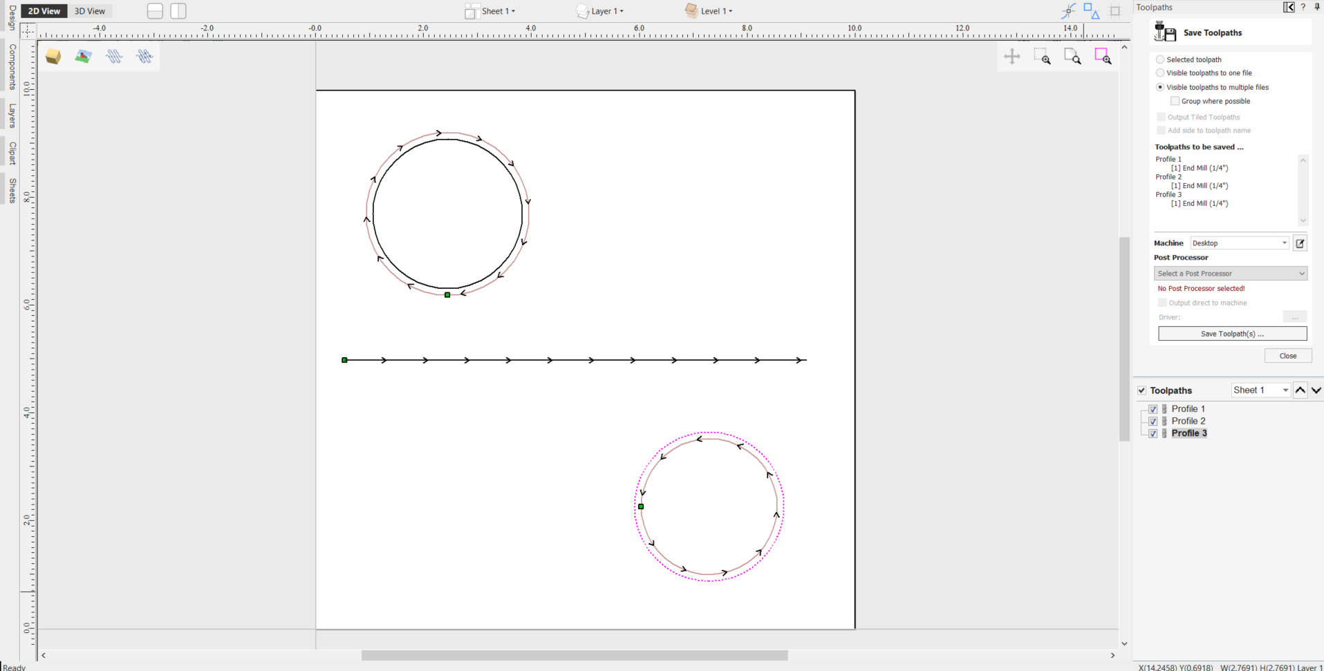
Save a toolpath using your base post processor and take a look at it using your favourite text editor. Below is an example of the test file posted using the "G-Code Arcs (inch) (*.tap)" post processor The example below is displayed using the popular Notepad ++ editor.
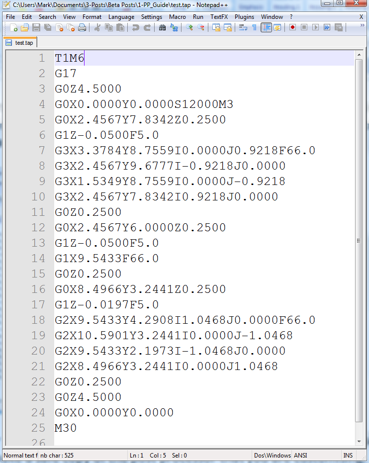
For our example, we will add a tool-change section to this post processor. Go to the Machine Configuration option under the machine menu.
In the Associated Post Processor section, click on the (+) icon and scroll down the list to locate your Post Processor in the list.
Right click on it and select Customise
A new copy of the Post Processor will appear at the top of the list with a pen icon next to it.
Right click on this copy and select Open File Location
This will open the Windows folder with the .pp Post Processor file itself which you can then directly edit if you need to adjust commands to fit your particular machine setup. These .pp Post Processor files can be edited in any standard Text Editor software
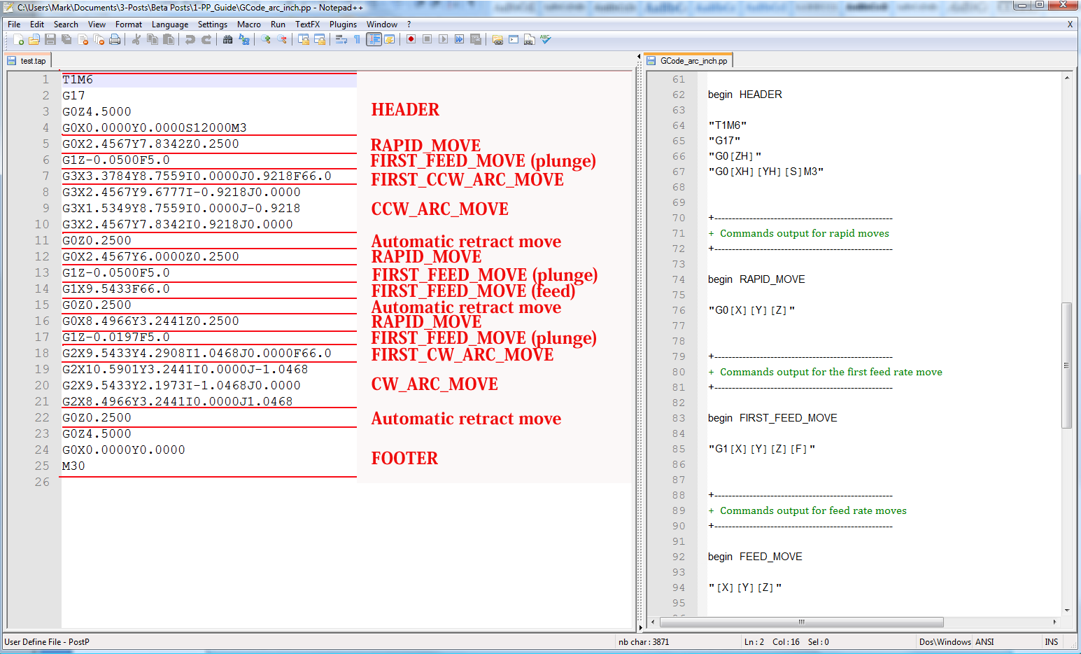
To add a Tool Change section to the post processor, you will need to consult the documentation for the control of the machine tool (or control software). For this example, we will assume that the instructions that you need to add to perform a tool change for your particular machine tool are as follows:
- M05 Instruction to turn off the spindle prior to tool change.
- M0 Instruction to return existing tool to tool holder.
- M06TTool_Number n Instruction to select new tool Tool_Number n
- G43HTool_Number n Instruction for control to use Tool length offset for tool n
- Sxxx M03 Set spindle speed to xxx; Turn on spindle (clockwise rotation).
Edit the post processor using your favourite text editor.
If the operating system on your computer is Microsoft Vista and User Access Control is enabled, copy or move the Post Processor that you are editing from the PostP folder to a folder below your user area.
The first thing that you should edit within the file is the History Comment section; So that you have a record of the changes.
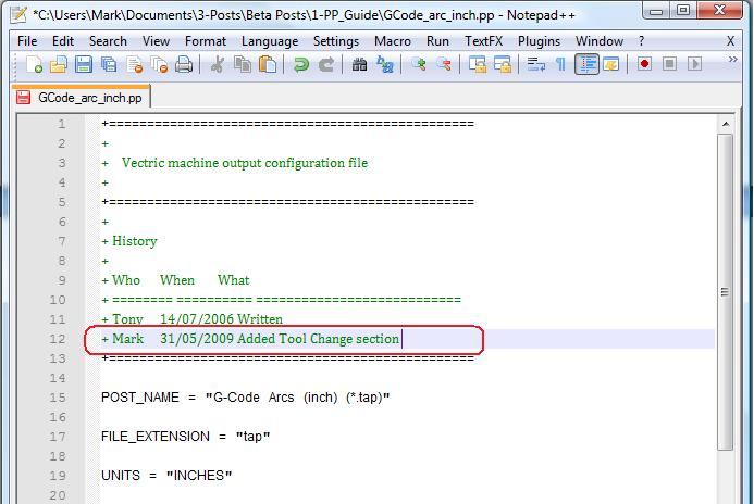
Next edit the POST_NAME to reflect that this post processor outputs automatic tool change (ATC) commands, the new post will be displayed as “G-Code ATC Arcs (inch)(*.tap)” in the list of post processors.
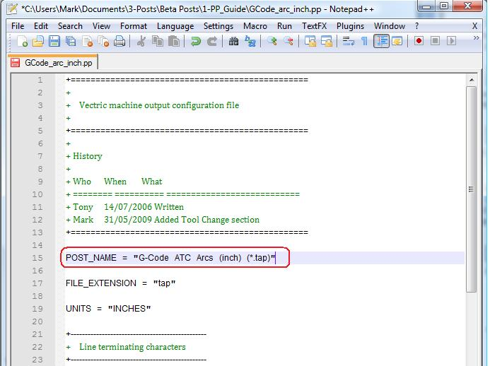
Next add a Tool Change Section that will include the instructions. The location of the new section within the file is not important, but a good place to insert it is between the Header and Rapid Move sections.
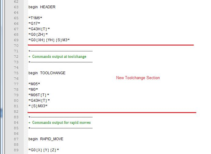
Add some comment lines at the top of the new section, (beginning with the + character) to describe the section and make the file as a whole, easier to read. Next enter the line “begin TOOLCHANGE” to instruct the post processor that the following instructions are to be output for every tool-change, (except the initial tool selection, the commands for these are contained within the header section).
The next step is to enter in the instructions that you require, enclosed within double quote marks. The “[T]” on the third and fourth instruction lines of our example, will be substituted with the tool number when the file is post processed; The “[S]” on the fifth line will be substituted with the spindle speed for the tool.
Finally you will need to save the changes to the file, as you have changed the POST_NAME, save the file using a new name, for example “GCODE_ATC_Arcs_inch.pp”
If the operating system on your computer is Microsoft Windows 7 or Microsoft Vista and User Access Control is enabled, copy the file that you have edited back to the “PostP” folder.
To test the new post processor, If the software is running, restart the software.
If there are any syntax errors with your post processor, an error similar to the picture below will be displayed as the software starts, the post processor that you have edited will not appear in the drop down list of post processor configuration files. You will need to rectify any errors and restart the software.
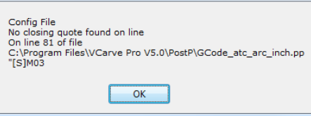
If there are no errors displayed when the software is started, open your test file and save one or more of your test toolpaths.
Select the post processor from the drop down list of post processor configuration and press the “Save Toolpath(s)” button.
Take a look at the file that you have just saved in a text editor.
If the content of the file looks good, try the file on your machine.
Please take all necessary precautions when running the output from a modified post processor for the first time.
Example: Changing the File Extension
The File extension that is automatically produced by the post processor can be changed within the “Save As” dialog box, when you click on the “Save Toolpath(s)” button.
However, rather than change the file extension every time. It is more convenient to permanently change the file extension produced by the post processor.
To do this:
For our example, we will add a tool-change section to this post processor. Go to the Machine Configuration option under the machine menu.
In the Associated Post Processor section, click on the (+) icon and scroll down the list to locate your Post Processor in the list.
Right click on it and select Customise
A new copy of the Post Processor will appear at the top of the list with a pen icon next to it.
Right click on this copy and select Open File Location
This will open the Windows folder with the .pp Post Processor file itself which you can then directly edit if you need to adjust commands to fit your particular machine setup. These .pp Post Processor files can be edited in any standard Text Editor software
Edit the post processor using your favourite text editor.
If the operating system on your computer is Microsoft Windows 7 or Microsoft Vista and User Access Control is enabled, copy or move the Post Processor that you are editing from the PostP folder to a folder below your user area.
Look for the following two lines within the post processor configuration file that begin with:
POST_NAME =
FILE_EXTENSION =
and alter these accordingly.
For example, if you wished to change the file extension produced by the “G Code ATC (inch)(*.tap)” post processor from “.tap” to “.nc”. Then edit the lines:
POST_NAME = "G Code ATC (inch) (*.tap)"
FILE_EXTENSION = "tap"
to make them read:
POST_NAME = "G Code ATC (inch) (*.nc)"
FILE_EXTENSION = "nc"
Save the changes to your file. If the operating system on your computer is Microsoft Windows 7 or Microsoft Vista and User Access Control is enabled, copy the file that you have edited back to the “PostP” folder.
To test the new post processor, If the software is running, restart the software. If there are any syntax errors with your post processor, an error similar to the picture below will be displayed as the software starts, the post processor that you have edited will not appear in the drop down list of post processor configuration files. You will need to rectify any errors and restart the software.
If there are no errors displayed when the software is started, open your test file and save one or more of your test toolpaths.
Select the post processor from the drop down list of post processor configuration and press the “Save Toolpath(s)” button.
Take a look at the file that you have just saved in a text editor.
If the content of the file looks good, try the file on your machine.
Please take all necessary precautions when running the output from a modified post processor for the first time.
Tips And Tricks
1. Always make a safe copy of the post processor that you are editing, in case you need to start again from scratch.
2. If using a word processor program, such as Microsoft Word, to edit a post processor, make sure that the file is saved as plain text. The file should not contain formatting information.
3. If editing post processors on a computer that runs Microsoft Windows 7 or Microsoft Vista, do not edit the files directly within the “Program Files\Product folder\PostP” folder. Always edit the file within your user area and copy the edited file to “Program Files\Product folder\PostP”.
4. Use comments when you make changes, a comment is a text that follows a + or a | character. Comments will not be acted upon by the program but can help in documenting changes that you have made and make those changes understandable in the future.
5. All Instruction lines must be contained within quote marks.
6. If possible, use a text editor that makes use of line numbers; This will make it easier to debug the post processor if there are any errors in the file. The program will check the post processors in the PostP folder when the program starts. If syntax errors are present in the file, an error message will be displayed, showing the line number of the first error encountered.
7. Once you have successfully edited a post processor, make a safe copy of it. If you install a later version of the Vectric product that you are using, remember to copy your modified post processor to the PostP folder of the new version of the software. And select your modified post processor, the first time that you save a toolpath, (The software will remember your selection for subsequent actions).
8. If you install another version of the software or you upgrade the version of the software, remember to copy your safe copies of your edited post processors to the PostP folder of the new version. Ensure that you select the correct post processor the first time that you post process a file using the new version of the software.
9. For later versions of the software, ( V5.5 and above). The post processors should be accessed from within the application, by clicking “File > Open Application Data Folder\PostP folder.
10. A customized list of post processors can be created by copying only the post processors required to the “File > Open Application Data Folder\My_PostP folder. If any file with a .pp file extension exists in the “My_PostP” folder, then only the post processors that exist in the My_PostP folder will be displayed in the drop down list of post processors.