Nesting

The Nesting tool will automatically fit vector shapes within the user defined area in the most efficient way it can calculate (based on the user defined parameters). By default the area the vectors will be fitted is the current Job Size but it is also possible to select a vector as the nesting area. This is a powerful way to optimize material usage and increase toolpath efficiency when laying out and cutting a number of shapes.
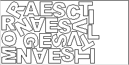
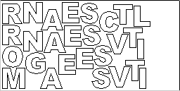
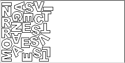
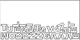
The image below left show a set of letters which have been typed out using the normal Text layout tool, the image on the right shows the same set of letters after the Nest Parts function has been used to optimize their layout. The Nest Parts tool will be documented in detail in this section to show how the options within the menu control the layout.
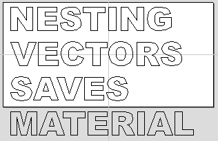
Before Nesting
After Nesting
What kind of yield should I expect from the Nest Parts command?
While the Nest Parts function within Aspire is designed to do as good a job as possible it is important to understand it will not always nest parts as well as an intelligent (and patient) human. The nesting in Aspire works incrementally and does not re-arrange parts it has already placed. Therefore it does not have the ability to adjust things as the parts are being fitted that a human nester might see could be more efficient.
The Nest Parts function excels when the parts are relatively small compared to the nesting area and there are a large number of parts to nest.
If you have a relatively small number of shapes to nest or you plan to cut the same set of parts many times then it may be better to take the time to manually nest your vectors. When you use the Nest Parts function and see some obvious places that you could do better this is a good indicator that manual placement may be better.
Sheets
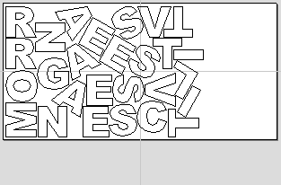
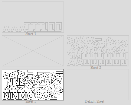
The amount of material required to Nest the selected vectors may be larger than the specified work area (Job Setup). To cope with any 'overflow' Aspire makes use of a new type of entity called Sheets. Sheets are used for any nested shapes that will not fit within the boundaries of the specified Job Size (or the selected vector). Additional Sheets will be created using the same parameters chosen to Nest the vectors. These are displayed to the right and above the current Job area as can be seen in the image shown below. The use of the Sheets will be explained in more detail in section below on choosing the Active Sheet within the Nest Parts form.
The concept of Sheets is very specifically related to machining the finished parts and is not designed to replace layers. Sheets should NOT be used to organize vectors for modelling or to organize vectors which you intend to use for different machining operations, in those cases the Layers should be used to manage the vectors.
The sole purpose of Sheets is to allow nested parts for production type machining to be laid across many units of the same material. Only vectors on the Default Sheet can be nested so Nest Parts should be the last command carried out on the parts before machining. As such objects should not be nested more than once, if you do not like the nesting solution then you should use the Undo (Ctrl + Z) command immediately and then make changes to the settings before trying the nesting again.
How Parts are Nested
Nesting shapes is a complex calculation which requires the user to make sure the vectors are in the correct state to get the results they are looking for, this is especially important when nesting overlapping vectors or designs that have sets of vectors that need to stay in position with each other. In certain situations it is necessary to group together particular vectors to get the correct result. For simple shapes within shapes such as an 'O', 'B', 'P' etc. there is no need to group them before nesting. Aspire will keep these internal shapes in the correct position and orientation as the shapes are nested.
If the 'outer' vectors of the items being nested are overlapping (and are supposed to be overlapping) then they should be grouped together. This will ensure that the software does not try and nest other items in incorrect places inside of these objects or break the components apart; the nesting for these groups will be done using the bounding box of all these grouped items.
Below you can see an example showing the value of this. The first image shows 3 parts to be nested 6 times each, they include overlapping vectors and single lines. The second image shows the parts nested WITHOUT Grouping as you can see the parts are split apart and the single lines are deleted. The 3rd image shows the parts Grouped before nesting into 3 specific groups, these keep all the parts in the correct position and does not delete the individual lines.
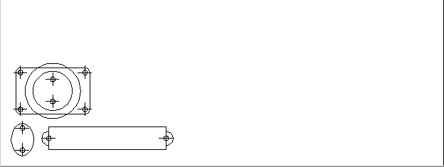
Original Parts
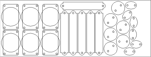
Nesting without Grouping
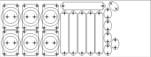
Nesting with Grouping
Original vector layers for grouped vectors will be remembered even if the vectors are nested. If nested and then ungrouped the objects within them will go back onto their original layers. This can be useful if you have arrangements of production parts which are on different layers that you need to nest. These might be parts which use layers for different machining operations (drilling, pockets etc.). To nest these you can do the following:
Group the complex component represented by vectors on different layers. Nest the grouped objects to optimize placement. Select all the vectors and Ungroup to get the data back on the original layers for machining.
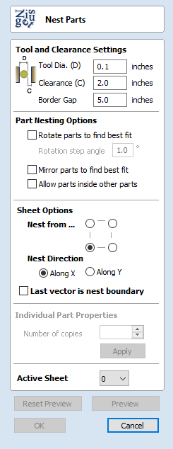
Once you click the icon you will see the form shown below. You can see there are a lot of options on this particular form, these will all have a bearing on how the parts are nested. Generally it is assumed that you are nesting parts for the purposes of machining so a number of the options are set in regard to the tooling you plan to use and parameters associated with cutting the parts out.
It is therefore very important to use the correct values that correspond to the machining choices you plan to make and keep a note of these so you use the correct values when you come to actually create the toolpaths.
Tool and Clearance Settings
The settings in this section of the form will determine the spacing which will be left between each of the nested vectors and also control how close they are to the edge of your nesting area.
Tool Dia. (D)
Enter the diameter of the tool that you will be using to Profile (cut-out) the vectors you are nesting. This is the minimum distance that will be left between shapes once they are nested.
Clearance (C)
The Clearance value will be combined with the specified Tool Diameter to create the final minimum spacing between the nested shapes. For example a Clearance of 0.05 inches combined with a Tool Diameter of 0.25 inches would create a minimum spacing gap of 0.3 inches (0.05 + 0.25 = 0.3).
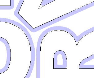
It is important to note that if you want actual material to be left between the nested shapes once they are cut out that the Clearance needs to be larger than the diameter of the tool. In the example used above where the minimum gap is 0.3 inches (0.05 + 0.25) the area machined by a 0.25 inches diameter tool cutting these shapes out would overlap as shown in the image to the left below (the blue shows the area which would be removed by the tool), this would leave no material between some of the parts.
If you wanted there to be material between the cut-out passes then you would need to specify a Clearance value larger than the Tool Diameter. For instance a Clearance of 0.3 inches would make a total gap of 0.55 inches, this is shown in the image below right. This would leave a minimum of 0.05 inches of material that would be left once the tool had cut out the shapes. This would be very important if using tabs to hold your parts in place, or if you wanted to prevent the scrap from potentially jumping off the table.
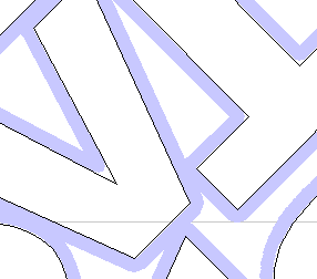
Clearance less than Tool Diameter
Clearance greater than Tool Diameter
Border Gap
The Border Gap value is applied to the edge of the area which is being used to nest the vectors into. It will be added to the Clearance value around the edge of this shape to create the minimum distance that parts will be nested in respect to the nesting boundary.
Vectors can be nested either within the whole Job area or into another selected vector (see section below on Last vector is nest boundary for more information on that option). The shapes will be nested as close to the edge as possible using the Clearance specified to determine the minimum distance from the edge. In many situations it is beneficial to have an extra gap from the edge of the material to ensure that the tool does not overlap into an area where there may be clamps (or other obstacles) and to ensure that some material is left for hold-down.
The Border Gap can be used to define this extra distance. In many cases it would be defined as the tool diameter or an even larger value. Below left the image shows no Border Gap, below right you can see a Border Gap has been defined leaving a boundary area around the edge of the nesting area.
No Border Gap
Border Gap
Part Nesting Options
The options in this area of the form will all directly affect how many parts or how efficiently it is possible for the software to fit shapes into the defined nesting area. The use of these options may depend on the particular material and application you are going to be using your cut parts for. Think carefully about the effect they will have on your shapes to ensure it does not adversely affect the finished cut parts.
Rotate Parts to find best fit
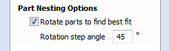
Checking ✓ this option will allow the software to rotate the selected vectors in order to try and better fit them. The increments of rotation the software will use is based on the Rotation step angle which is defined in the form area shown below.
In theory the smaller the specified angle the more options the software will have to fit the shapes together so the more efficient the nesting will be. This does depend on the shape of the vectors though. It should also be noted that the smaller the angle specified the longer the nesting will take to calculate. Un-checking this option will ensure the parts keep the same orientation that they had when selected. This could be important if you are working with shapes that need to be oriented in a specific direction, for instance in regard to the material grain.
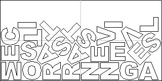
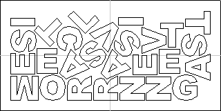
Rotate Parts Enabled
Rotate Parts Disabled
The image above and left shows the letters nested with 30 degree rotation and the image above right shows the same letters nested with NO rotation. As you can see, by allowing the rotation the software can fit the letters into a smaller area. In this case it is not a huge difference but the more shapes there are and depending on the style of the shapes it could be a bigger margin.
Mirror parts to find best fit
Checking ✓ this option will allow the nesting to mirror (flip) the vectors in order to try and more efficiently nest the selected shapes. This should only be checked ✓ if the direction the parts are cut in is not important. For instance if you are using pre-finished material you would always want the face of the part to the top of the material and so would not want to allow the software to mirror them. If the parts were being cut-out and then finished or depending on the material being cut this may not be an issue and so could be used to help fit more parts into the nesting area.
Allow parts inside other parts
Checking ✓ this option will allow the software to nest within the internal areas of shapes that have gaps in the middle. This would be a good way to optimize material if you were cutting out parts but would not be a good choice if the inside of the shapes was only going to be pocketed as it would not then be scrap material. Grouped objects will not allow shapes to be nested within them even if they appear to have space to fit the smaller items. They would need to be ungrouped to allow the software to use the internal regions. Standard typed text will allow nesting on inside areas as shown in the example below.
In the two images below you can see a set of letters which are going to be cut out. The larger letters have sizable internal areas that will become wasted scrap, using the Allow parts inside other parts option means that Aspire will use these internal areas to fit any smaller parts into them. This can be seen in the right hand image which shows the letters after nesting, where the inside of the O's and the B have been used to nest the smaller shapes.

Original
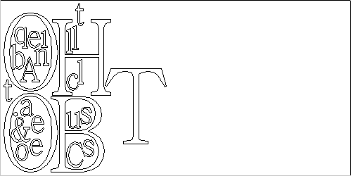
Parts Nested inside other parts
Sheet Options
Nest From
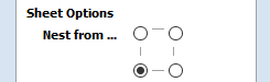
This area of the form is used to define which corner the nesting will start in. There are four options which can be selected from the options in the form.
Each node corresponds to the respective corner of the Material or the selected boundary vector. The first nested parts will be placed in that corner and the shapes fitted according to the Nest Direction specified (see section below).
Nest Direction
The options in this area of the form are used to select how the parts will progress as they are positioned within the sheet. The best way to think of this (for the purposes of this section) is that they 'pour' out of the selected corner filling the sheet in one axis then advancing along the other defined axis (X or Y) .
Along X
Checking ✓ this option means the nested vectors will fill the boundary area vertically then progress horizontally along the X axis, radiating from the corner selected in the Nest From section of the form. The image below shows the Along X nesting option with Nest from... set to the lower left corner.
Along Y
Checking ✓ this option means the nested vectors will fill the boundary area horizontally then progress vertically along the Y axis, radiating from the corner selected in the Nest From section of the form. The image below shows the Along Y nesting option with Nest from... set to the lower left corner.
Last vector is nest boundary
Checking ✓ this option means the last vector selected will be used as the boundary for the nesting area. This can be useful if you need to define a non-rectangular shape to Nest Parts into, such as large off-cuts from a previous job. It's important to note that using this option will not respect the currently defined Job Area if the selected boundary vectors goes outside of it. If there are too many vectors to fit into the last selected vector then additional Sheets will be created using the same boundary shape for the parts being nested, the boundary vector will be positioned on the Default Sheet (zero) along with any items not selected for nesting.
Not having the Last vector is nest boundary option checked ✓ means all the selected vectors are nested into the whole of the defined Job Area (defined by the Job Setup form accessed from 'Edit - Job Size and Position' from the menu bar).
Individual Part Properties
This function is very useful if you have a number of the same part to make and need to nest many parts at once. It allows multiple copies of the selected object/s to be nested without making the copies prior to the operation.
If you want more than one incidence of a particular item then select it from the 2D view. In the box where it says Number of Copies enter as many copies as you want and hit and the selected vectors will be marked with a green number indicating how many copies of that item will be made when they are nested. Different shapes or groups of shapes can be assigned different numbers of copies. To stop an item being copied multiple times just set the Number of Copies back to 1 and click .
Active Sheet
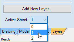
This option lets you choose which Sheet of vectors is currently active, either for editing or applying toolpaths onto.
The Active Sheet can also be chosen when the Nest Parts form is not open by using the drop down option from the base of the Layers menu - this is shown in the image below left highlighted with a red box, the image below right shows the drop-down with the choice of currently available Sheets.