Profile Toolpath

Profile Machining is used to cut around or along a vector. Options provide the flexibility for cutting shapes out with optional Tabs / bridges plus an Allowance over/undercut to ensure perfect edge quality.
Profile toolpaths can be outside, inside or on the selected vectors, automatically compensating for the tool diameter and angle for the chosen cut depth.
When working with open vectors the profile toolpaths can be to the Left, to the Right or On the selected vectors.
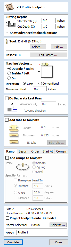
Clicking this icon opens the 2D Profile Toolpath form which is shown at the right; the functions in this form are described on the following pages.
If you have vectors which are nested (like the letter 'O'), the program will automatically determine the nesting and cut the correct side of the inner and outer vectors. In addition, the program will always cut the inner vectors before the outer vectors to ensure the part remains attached to the original material as long as possible.
Cutting Depths
Start Depth (D)
Specifies the depth at which the Profile toolpath is calculated. When cutting directly into the surface of a job the Start Depth will usually be 0. If machining into the bottom of an existing pocket or stepped region, the depth of the pocket / step must be entered.Cut Depth (C)
The depth of the profile toolpath relative to the Start Depth.Tool
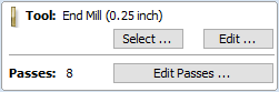
Clicking the Select button opens the Tool Database from which the required tool can be selected. See the section on the Tool Database for more information on this. Clicking the Edit button opens the Edit Tool form which allows the cutting parameters for the selected tool to be modified, without changing the master information in the database. Hovering the mouse cursor over the tool name will display a tool tip indicating where in the Tool Database the tool was selected from.
Pass Depth Control for Profiling
When a profile toolpath is created, the Pass Depth value associated with the selected tool (part of the tool's description in the Tool Database) is used to determine the number of passes needed to profile down to the specified Cut Depth. However, by default Aspire will also modify the precise step down by up to 15% in either direction, if by doing so it is able to total number of passes required to reach the desired cut depth. It is nearly always desirable to benefit from the significantly reduced machining time of cutting profiles using less passes if possible. Nevertheless, there are some occasions where the exact step down for a given profile pass needs to be more precisely controlled - when cutting into laminated material, for example. The Passes section of the 2D Profile Toolpath page indicates how many passes will be created with the current settings. button will open a new dialog that enables the specific number and height of passes to be set directly.
Specify Pass Depths
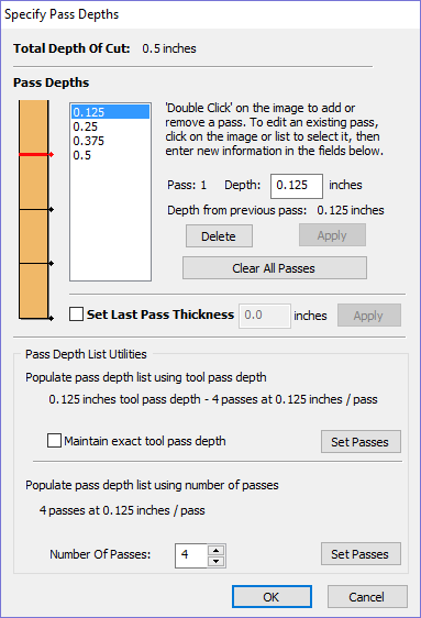
The Pass Depths section at the top of the form shows a list of the current pass depths. The relative spacing of the passes is indicated in the diagram next to the list. Left click on a depth value in the list, or a depth line on the diagram, to select it. The currently selected pass is highlighted in red on the diagram.
To edit the depth of the selected pass, change the value in the Depth edit box and click .
The button will delete the selected pass.
The button will delete all the passes.
To add a new pass, double left click at the approximate location in the passes diagram that you wish to add the pass. A new pass will be added and automatically selected. Edit the precise Depth value if required and then click .
The Set Last Pass Thickness option will enable an edit box where you can specify the last pass in terms of the remaining thickness of material you wish to cut with the last pass (instead of in terms of its depth). This is often a more intuitive way to specify this value.
Pass Depth List Utilities
This section of the form includes two methods for creating a set of passes in one go.
The first method simply sets the passes according to the Pass Depth property of the selected tool. By default, this is the method used by Aspire when it creates profile passes initially. However, the Maintain exact tool pass depth option checked, ✓ Aspire will not vary the step size to try and optimize the number of passes (see above).
The second method creates evenly spaced passes according to the value entered in the Number Of Passes edit box.
To apply either method click the associated button to create the resulting set of pass depths in the passes list and diagram.
Machine Vectors...
There are 3 options to choose from to determine how the tool is positioned relative to the selected vectors/s.
Outside |
|
Calculates a profile toolpath around the Outside of the selected vectors, with options for the cut direction to be either, Climb (CW) cutting direction or Conventional (CCW) cutting direction |
Inside |
|
Calculates a profile toolpath around the Inside of the selected vectors, with options for the cut direction to be either; Climb (CCW) cutting direction or Conventional (CW) cutting direction |
On |
|
Calculates a profile toolpath around the On the selected vectors, with options for the cut direction to be either, Climb (CW) cutting direction or Conventional (CCW) cutting direction |


Direction
Can be set to either Conventional or Climb machining where the cutting direction depends upon the strategy selected - see above for details. Using Climb or Conventional cutting will largely be dictated by the material is being machined and the tooling.
Allowance offset
An Allowance can be specified to either Overcut (negative number will cut smaller) or Undercut (positive numbers will cut larger) the selected shape. If the Allowance = 0 then the toolpaths will machine to the exact size.
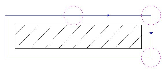
Last Pass Allowance
A separate allowance can be specified for the last pass. If this allowance is given then all but the last pass will be undercut by the specified allowance with the final pass being the only pass which cuts to size.
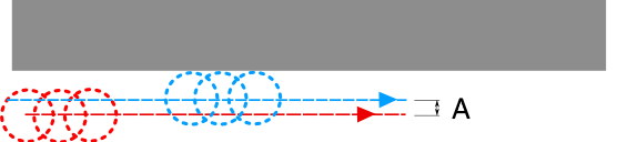
The final pass (shown in blue) cuts to size.
All previous passes (shown in red) are cut with a small allowance offset
If the Reverse direction button is checked ✓ then the cutting direction of the last pass is reversed. This feature is can be useful if for minimizing witness marks on the edge of profile cuts.
The last pass allowance will also take into account any allowance offset and so the two options can be used together.
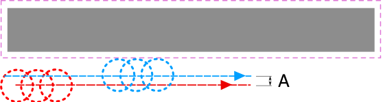
The last pass allowance will respect any allowance offset also specified
Use vector start point
Use Start Point can be selected to force the toolpath to plunge and start cutting at the first point on the shape. This is very useful if you need to ensure the cutter doesn't plunge onto a critical part of the job. For example, setting the Start Point to be on a corner will often be the best position to plunge and cut from as this will not leave a witness / dwell mark on the machined surface.
The Start Points are displayed as Green boxes on all vectors when this option is selected. Start Point on a vector can be moved using the Node Editing Tools. Select Node Editing cursor or press N. Place the cursor over the node to be used as the Start Point. Click Right mouse button and select Make Start Point (or press P) Remember, you can also insert a new point anywhere on a vector using the Right mouse menu or pressing the letter P - this will insert a new point and make it the start point.
Tabs (Bridges)
Tabs are added to open and closed vector shapes to hold parts in place when cutting them out of material.
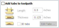
Add tabs to toolpath
Checking ✓ the Add tabs option will activate tab creation for this toolpath. The Length and Thickness specify the size of each tab. Checking ✓ the Create 3D Tabs option will create 3D Tabs, the difference between this and 2D Tabs is described below.
Create 3D Tabs
When this option is selected the tab will be triangular in section. This is shape is created as the cutter ramps up to the specified Tab Thickness then down the other side. The 3D Tabs will often allow the machine to run quicker and smoother because it does not have to stop to move in Z at the start and end of each tab.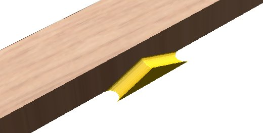
3D Tabs option selected
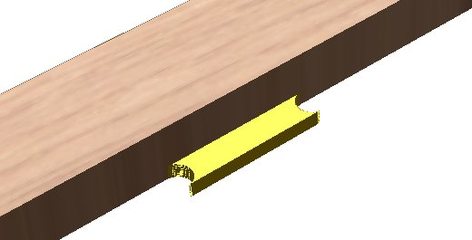
3D Tabs option not selected
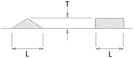
This image shows how the Length and Thickness values are used when creating 3D and 2D tabs.
Edit Tabs
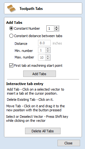
Clicking on the button automatically opens the 2D window and the Toolpath Tabs form is displayed:
Add Tabs
Constant Number
Calculates the length of each selected vector and places 'X' number of equally spaced Tabs around the shape.
Constant Distance between tabs
This option places a tab at the specified distance around the selected shape.
If placing Tabs at the Distance around the shape results in fewer than the Min. number, the minimum number of Tabs are automatically equally placed on the shape.
If the number of tabs calculated using the Distance around the shape is greater than the specified Max. number, the maximum number are placed at equal distance around the shape.
First tab at machining start point
If checked, ✓ a Tab will be placed at the start point (Green node) of a vector when the option First Tab at Machining Start Point is selected.
Dynamically positioning tabs in the 2D View
Interactive Tab positioning is very easy. Simply place the cursor at the point where the Tab is required and click the Left mouse. To Move a Tab, Click and Drag with the Left mouse button on a Tab to move.
To Delete a Tab, place the cursor over an existing tab and click the left mouse button.
The quickest method for adding Tabs to multiple shapes is to use the automatic option to add 'X' number. The position of these can then very easily be modified by clicking and dragging to move tabs to the 'best positions' and also delete unwanted tabs.
Profile Options
The Profiling options section of the toolpath form contains five additional pages, each of which allows a particular set of Profile machining options to be specified. The precise number of option pages will depend on which Toolpath strategy you are currently using. The full range of option pages are:
- Ramps
- Leads
- Order
- Start At
- Corners
These help control ways to ensure the parts are held in place and machined as easily as possible while ensuring the highest quality edge finish.
Each set of options can be accessed by the tabs at the top of the Profile options section.
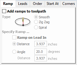
Ramp
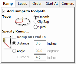
Ramp moves are used to prevent the cutter from plunging vertically into the material. The cutter gradually cuts at an angle dropping into the material significantly reducing cutter wear, heat build-up and also the load on the router spindle and Z axis of the machine. If multiple passes are required due to the Pass Depth being less than the Cut Depth, the ramp moves are applied at the start of each level. All ramp moves are performed at the plunge rate selected for the current tool.
Smooth
This option creates a smooth ramp into the material using either the specified Distance or Angle.
When a Lead In distance has been specified, the option Ramp on Lead In disables the distance and angle options and automatically limits the ramp moves to only be on the lead in portion of the toolpath.
Zig Zag
This option ramps into the material by Zig-Zag backwards and forwards using either the specified Distance or Angle and Distance.
The Distance option ramps into the material, zigging for the specified distance in one direction then zagging back over the same distance.
The Angle option is typically used for cutters that cannot plunge vertically but have an entry angle specified by the manufacturer.
Spiral
Checking ✓ this creates a continual spiral ramp, these are only available when the toolpath does not include lead in moves.
This option ramps into the material over the complete circumference of the profile pass. The angle is automatically calculated to ramp from the start point to full depth over the perimeter distance around the job.
The rate at which the cutter ramps into the material is determined by the Pass Depth specified for the cutter. For example, Spiral Profiling 0.5 inch deep with a cutter that has a Pass depth of 0.5 or greater will spiral down in 1 pass. Editing the Pass depth to be 0.25 inch results in the 2 spiral passes around the profile.
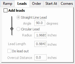
Leads
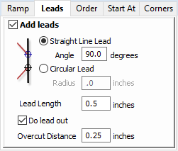
Lead in / out moves can be added to profile toolpaths to help preventing marking the edges of components with dwell marks that are typically created when a cutter is plunged vertically on the edge of the job.
Straight Line Lead
This option creates a linear lead onto the cutter path using the Angle and Lead length distance specified.
The toolpath will lead onto the selected edge at the specified Angle.
Checking ✓ the Do lead out option results in an exit lead being added at the end of the toolpath off the machined edge.
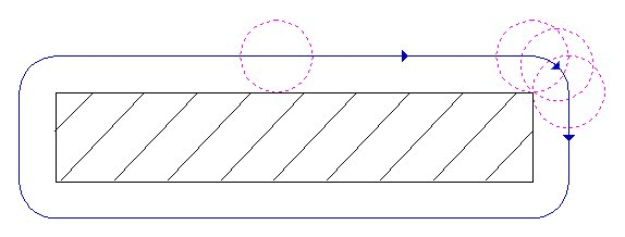
The Overcut Distance forces the cutter to machine past the start point and is often used to help produce a better edge quality on parts.
Circular Lead
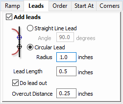
This option creates an arc lead onto the toolpath using the Radius and Lead length distance specified.
The toolpath will curve onto the selected edge, tangent to the direction of the vector at the point it reaches the actual geometry edge.
Checking ✓ the Do lead out option results in an exit lead being added at the end of the toolpath off the machined edge.
The Overcut Distance forces the cutter to machine past the start point and is often used to help produce a better edge quality on parts.
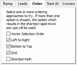
Order
The order tab allows you to specify the approaches the program will use to determine the best order to cut your vectors. You can specify multiple options, in which case the program will calculate the result of using each option and select the one which results in the shortest machining time.
Vector Selection Order
 This option will machine the vector sin the order in which you selected them.
If you have vectors inside each other (like in the letter 'O'), the inner vector will always be machined before the outer one regardless of the selection order.
This option will machine the vector sin the order in which you selected them.
If you have vectors inside each other (like in the letter 'O'), the inner vector will always be machined before the outer one regardless of the selection order.
Left to Right
This option will join up parts on the left of the material first and move across to the right.
Bottom to Top
This option will join up parts on the bottom of the material first and move up to the top.
Grid
This option will join use a grid based approach with the size of the grid based on the size of the parts. The algorithm will try to join up parts within a particular section of the grid before moving on.
Shortest Path
This option use a 'shortest path' algorithm to try and determine the shortest possible path. However, for large numbers of parts this requires an unfeasible amount of computing power so an approximation algorithm is used. Although very good, this algorithm cannot guarantee to produce the very shortest path, but in tests at Vectric, the results have been very good indeed. This option still takes a substantial amount of time on slow computers of for very large numbers of parts.
Start At
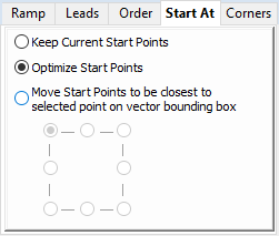
Keep Current Start Points
The start point of the vector will dictate the start of the toolpath.
Optimize Start Points
The software will automatically attempt to optimize each profile start position based on speed of completing the job.
Closest on Bounding Box
Influence the start point by defining which part of the bounding box of the profiled vector it should start near.
This will look for the nearest point, from all of the spans' endpoints, and will start the toolpath from that point.
Corners
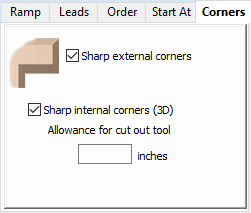
Choosing this tab and checking ✓ the option Sharp external corners (see below) forces the cutter to machine around the shapes and retain any square corners.
Sharp External Corners
This option makes adding beveled edges to a 2D shape very quick and easy, this can be a good way to turn simple 2D cut out lettering into a high quality signage products that look more interesting or provide a different option for customers.
This is an example of the type of effect that can be created by using this option:

Standard Profile toolpaths without the Sharp Corners switched on roll around the sharp corners. This Still give a point on a straight sided tool but will give a radiused edge when using a V-bit.
When Sharp External Corners is selected the following change is made to the toolpath (see image below) so it makes sharp external corners as shown in the image of the letter 'M' at the top of the page.
Sharp Internal Corners
When Sharp Internal Corners is selected the V-Bit tool will raise up into internal corners to sharpen them with its point. The difference between checking ✓ this and leaving it unchecked is shown in the two images below.
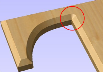
Sharp Internal Corners not selected
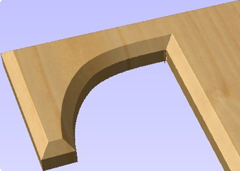
Sharp internal corners selected
Allowance for Cut out tool
Sharp internal corners are often used when creating beveled letters. In this case, the letters usually have straight 'returns' which are machined with a straight sided end mill. The cut out pass for the end mill needs to be offset from the vector to allow for the bevel created by the tool. This field displays the value you will need to enter into the 'Allowance Offset' field when you create your cut out profile toolpath for the end mill. You can select the value with the mouse and used Ctr+C to copy it to the clipboard and then copy it into the 'Allowance Offset' field when you create the cut out toolpath.
Additional notes on Profile Machining
Machining Open Vectors
The direction of open vector(s) is very important when using Profile strategies as this is used to determine which side of the selection is the right and left for machining. Selecting Node Edit mode (pressing N on the keyboard) will display a Green node at the start of the vector. Looking along the vector(s) from the green node indicates the direction and the image below shows offsets to the left and right of an open vector.
The Cut Direction - Conventional or Climb controls which end of the open vector the toolpath will start. Changing the cut direction will reverse the direction of cut.
Conventional starts cutting at the Start point Climb cutting starts cutting at the end pointIn the following examples, the vector is the magenta dotted line and the arrowed line is the toolpath:
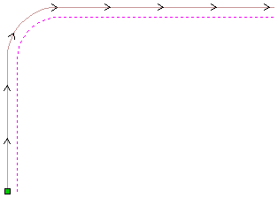
Profiling the Left of the vector using Climb cutting.
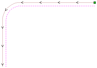
Profiling the Left of the vector using Conventional cutting
Talk to your material and tooling suppliers for details about what is most appropriate for your specific type of work.
Tabs can be added to open profile toolpaths Sharp External Corner options do not apply because identifying the outside / inside of an open shape in ambiguous. Leads cannot be added to open profile toolpaths. Ramps can be added to open profile toolpath.
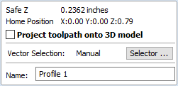
Safe Z
The height above the job at which it is safe to move the cutter at rapid / max feed rate. This dimension can be changed by opening the Material Setup form.
Home Position
Position from and to that the tool will travel before and after machining. This dimension can be changed by opening the Material Setup form.
Project toolpath onto 3D Model
This option is only available if a 3D model has been defined. If this option is checked, ✓ after the toolpath has been calculated, it will be projected (or 'dropped') down in Z onto the surface of the 3D model. The depth of the original toolpath below the surface of the material will be used as the projected depth below the surface of the model.
Vector Selection
This area of the toolpath page allows you to automatically select vectors to machine using the vector's properties or position. It is also the method by which you can create Toolpath Templates to re-use your toolpath settings on similar projects in the future. For more information, see the sections Vector Selector and Advanced Toolpath Templates.
Name
The name of the toolpath can be entered or the default name can be used.