The Tool Database

The Tool Database is used to make cutter management and selection very quick and easy, and reduces the possibility of programming jobs with incorrect cut depths and speeds and feeds. The Tool Database is accessed from the button every time you create a new toolpath and allows pre-defined tools and settings (speeds, feeds, stepover etc.) to be selected from a list.
New tools can be added, copied from existing tools, deleted and organized. All of the cutting parameters are stored in the database.
Opening the tool database
To access the Tool Database you can click on the Database icon on the Toolpaths Tab:
Alternatively, select Toolpaths ► Tool Database from the main menu bar.
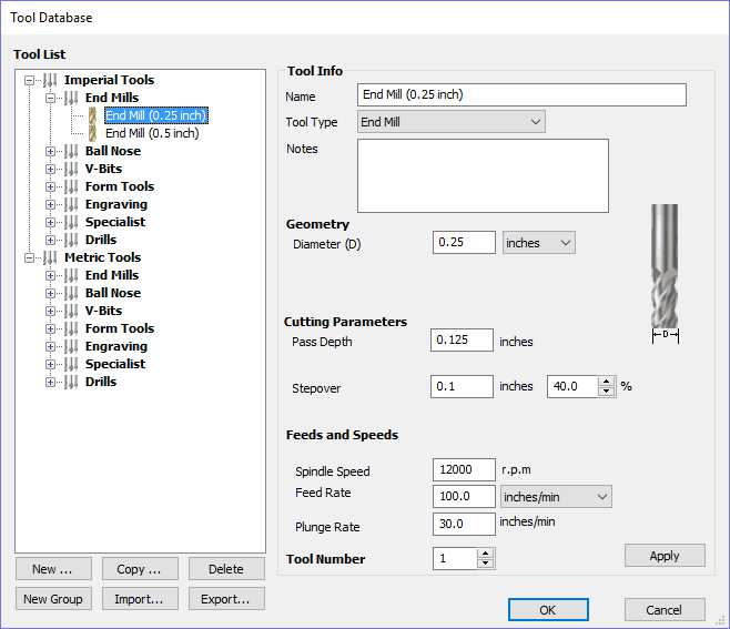
A window similar to that shown will appear displaying a list of the tools that are currently defined on the left and the parameters for the currently selected tool from the list over on the right. Below this image is a list of all the actions that can be executed from this dialog:
Tool List
The Tool List is located on the left-hand side of the Tool Database. Click on items in the list to see or edit their properties using the Tool Info section of the database window. The Toolpath list is arranged hierarchically to allow you to organize your tools according to common properties or use.
You can click and hold down the left mouse button to drag items up or down in the list. If you drag them into a tool group, they will be placed inside the group.
Tooltip of group hierarchy
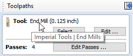
When a tool is selected within a toolpath strategy page, the tool name does not always provide enough information for you to know whether the tool's settings are appropriate. This will become particularly significant if you import a toolpath template (see Toolpaths Templates) with a tool that has been pre-defined (perhaps by a 3rd party) when the template was created. It is always possible to click Edit and see the full set of the tool's properties and settings. However, if you hover your mouse over the tool's name, a tooltip will pop-up telling you what the location of this tool was in the tool group hierarchy when it was added to the toolpath strategy or template. This can be extremely useful for quickly distinguishing between tools in your database that have similar names, but have been grouped according to their properties.
Adding a New Tool
Selecting creates an empty tool in the list that can have any user definable name.
Copying a New Tool
Copy adds a duplicate of the selected tool to the list and prefixes the original name with (1). Edit the Name and properties for the new tool and click the Apply button to save the changes to the list.
Deleting a Tool
Deletes the selected tool from the database.
Creating a new tool group
Click on the add button then give your new group a name and press to add it to the database. Click and drag tools from the database over the top of the newly created group icon in the tool database tree to add them to the group. Alternatively, select the group and then click the button to create a new tool directly within the selected group.
Importing and Exporting tools
Individual tools or complete tool group hierarchies can be saved to disk using the button. Similarly, you can import previously saved tools, groups or even entire tool databases using the button.
Tool Info
When a tool or group is selected in the Tool List, its properties are displayed in the Tool Info section on the right-hand side of the Tool Database.
Here you can modify any of the properties of the currently selected Tool or Group. Click the button to save the changes to the Tool List.
Name
Use this field to enter a suitable name to describe your cutters.
Tool Type
Various cutters can be specified in the database.
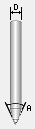
V-Bit
Engraving
Tapered Ball Nose
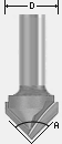
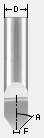
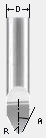
When specifying the geometry for a tool, the angle specified is different for V-Bit and Engraving Tools.
V-Bit Tools are defined using an Included Angle (A)
Engraving Tools are defined using the Half Angle (A) and the Flat Diameter (F)
Ball Nose
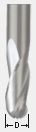
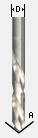
End Mill
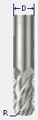
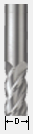
Radiused End Mill
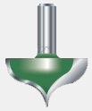
Form Cutters
Diamond Drag
Drills
Notes
The tool notes section simply allows you to save any additional text descriptions, special instructions or relevant information you may require, within your tool definition.
Geometry
Diameter
The diameter of the tool in either inches or mm. The tool image will indicate where this dimension is taken from. If you change the tool diameter but do not change the tool name then you will be warned.
Cutting Parameters
Pass Depth
The maximum depth of cut the tool can cut. The Pass Depth controls the number of z level passes that are calculated for a toolpath. For example, creating a pocket 1 inch (25.4 mm) deep using a tool that has a Pass Depth of 0.25 inches (6.35 mm) will result in the toolpath making 4 passes.
Stepover
The distance the cutter moves over when doing area clearance cutting. For example, when raster machining the cutter will machine along the X axis, stepover in the Y direction and return parallel to the first line of cut. The greater the stepover the faster the job will be machined, but this must be balanced with the material being cut and the tooling being used, to ensure that the tool does not break.
When stepover's greater than 50% of the cutter / tip diameter are used the software automatically adds 'Tail' moves in the corner regions of toolpaths to ensure material is not left on the job for offset based strategies. When using V-Bit Tools, the Stepover fields automatically change to use the following options.
Final Pass Stepover
The distance the cutter moves over when finish machining and is usually set to be a relatively small distance to produce a smooth surface finish on the job.
Clearance Pass Stepover
Only used when a V-Bit tool is being used to rough machine at multiple Z levels down to a specified flat depth. This stepover can be much larger than the Final Pass Stepover because the tool is only rough machining material away. Increasing the Clearance Pass Stepover will reduce the machining time, but you must be careful to ensure it is not too great for the material being cut.
Feeds and Speed
Spindle Speed
Speed of tool rotation, specified in revolutions per minute
Feed Rate
The surface cutting rate at which the cutter is moved in the material. The units can be specified in distance per second or minute.
Plunge Rate
The cutting rate at which the cutter is moved vertically into the material or during ramping moves. The units can be specified in distance per second or per minute.
Tool Number
This is the number of the tool needed to machine the job. When using a CNC machine with an Automatic Tool Changer (ATC), it is critical that the correct tool required to cut the job is located in the corresponding carousel location.
Using Form Cutters
Form Cutters can be added to the Tool Database so that industry standard Ogee and Round-over type cutters, plus user definable custom shapes can be used for edge profiling and decorative carving. Examples of these types of cutters and the kind of cuts they can be used for are shown in the images below:
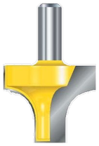
Round-over
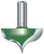
Ogee
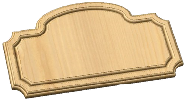
Profile Cutting Strategy with Form cutter
Adding your own custom form cutters
Adding a Form cutter to the Tool Database is straightforward and the procedure is,
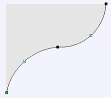
Before opening the tool database, draw to exact scale the Right side of the cutter geometry in the 2D Window Use the Node Editing tools to create the arcs and curves etc.Only draw the Right-hand side of the cutter geometry to the correct size and scale as shown in the image above.
The shape can be a combination of Lines, Arcs and Bezier spans. With the vector Selected open the Tool Database (using the command icon on Toolpaths tab or from the main menu, Toolpaths ► Tool Database In the Tool Database window, click Select Form Tool
The selected geometry will be imported and a profile displayed in the window.Give the Cutter a meaningful name and enter the cutting parameters - speeds and feeds etc. Click the button to save the new cutter into the database list so it can be used at any time.