Toolpaths

The ultimate purpose (in almost all applications) of Cut2D Desktop is to allow you to generate toolpaths which can be run on a CNC machine to machine the finished part in the material of choice. This requires, at a minimum, some vectors to describe the area to which a toolpath will be limited to. The process for creating toolpath is as follows:
Prepare vectors for machining
Optionally organize the vectors you will be using for machining onto appropriate layers.
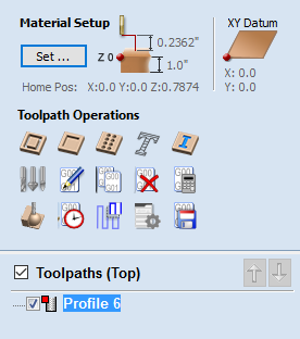
Set up the Material
Check the overall material size (Job Setup) to ensure it matches or exceeds the size of the finished product.
Use the Material setup form from the Toolpaths Tab to set the reference Z datum for the part relevant to the CNC machine.
Create the Toolpaths
Work through the toolpath strategy icons you wish to use to machine the job to calculate all the required toolpaths.
Preview the Toolpaths
Either after you create each toolpath or at the end of calculating them all, the user has the option to preview the toolpaths to see what they will actually look like in the 3D view. This is a very important step to verify position, detail and the look of the overall finished part.
Save the Toolpaths for the CNC machine
After choosing the appropriate Postprocessor from the list, the toolpaths can be saved in a format which is ready for the CNC to cut. Depending on the toolpaths calculated and the options the Postprocessor/CNC you are using supports, you may be able to save a single file or it may need multiple files to be saved - one for each tool type.
All the stages will be covered in the supplied Tutorial videos that include Machining. It should be noted Stage 1 is done through icons already covered from the Drawing Tab. Stages 2 to 5 use icons from the Toolpath Tab (on the right hand side of the screen). These will be covered in the next section.
Additional Toolpath Tab Features
Switch to Drawing Tab

Closes the Toolpath Tab (right hand screen form) and opens the Drawing Tab (left hand drawing form)

The pin icon is described in the section: Accessing Auto-hidden tabs
Toolpath Summary Area
When a toolpath is selected from the Toolpath list with no other function being used in the Toolpath Tab a text summary of the toolpaths settings is shown in the body of the Toolpath Tab below the icons. This is a very useful way to recall settings for a toolpath without opening it.