Chamfer Toolpath
The Chamfer Toolpath uses the selected vectors and tool to create an angled feature
The Chamfer Toolpath has two distinct ways of operating depending on the tool used:
- If the selected tool is an angled tool, then the angle of the tool determines the angle of the chamfer
- If the selected tool is a round nosed tool, then the angle of the chamfer must be specified manually, and will be approximated by a series of fine cuts.
Cutting Depths
The Start Depth (D) specifies the depth at which the top of the chamfer should start.
Vector Selection
To create the toolpath you must first draw and then select the vectors you wish to create the chamfer on.
Outil
En cliquant sur le bouton "Sélectionner", la base de données des outils s'ouvre et permet de sélectionner l'outil requis. Voir la section sur la base de données des outils pour plus d'informations à ce sujet. Cliquer sur le bouton Modifier ouvre le formulaire Modifier l'outil qui permet de modifier les paramètres de coupe de l'outil sélectionné, sans modifier les informations de base de la base de données. Si vous passez le curseur de la souris sur le nom de l'outil, une info-bulle s'affiche, indiquant l'endroit de la base de données des outils où l'outil a été sélectionné.
Chamfer Dimensions
The chamfer dimensions control the shape of the created chamfer.
Angle (A)
The angle determines the slope of the chamfer. It is measured from vertical. For a V-Bit tool then the angle is fixed to half of the angle of the tool. For a round nosed tool then the angle may be specified.
Width (W)
The width determines the horizontal size of the chamfer. If the angle is set then changing the width will change the cut depth proportionally.
Cut Depth (C)
The Cut depth is the height of the chamfer. If angle is set then changing the cut depth will change the width proportionally.
Max Cut Depth
To achieve the desired height of the chamfer, as specified by the cut depth field, cutting deeper might be required. This will be true in the case of a round-nosed tool.
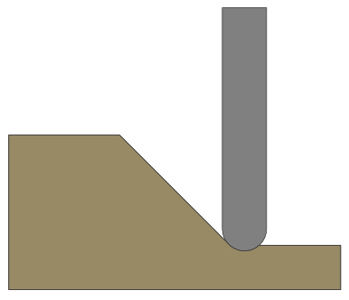
The Max Cut Depth field is read only and shows the full length of the cut so you can accurately see how deep the tool cuts.
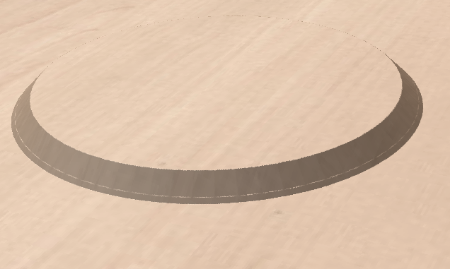
Chamfer Type
The Chamfer Type option controls whether or not a chamfer occurs on the inside or the outside of a vector and the direction of the slope of the chamfer:
- A chamfer inside will lie inside of the selected vector.
- A chamfer outside will lie outside of the selected vector.
The direction of the slope tells us whether or not our chamfer slopes upwards from our selected vector or downwards from our selected vector.
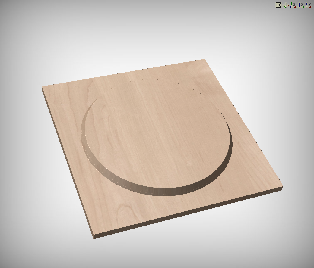
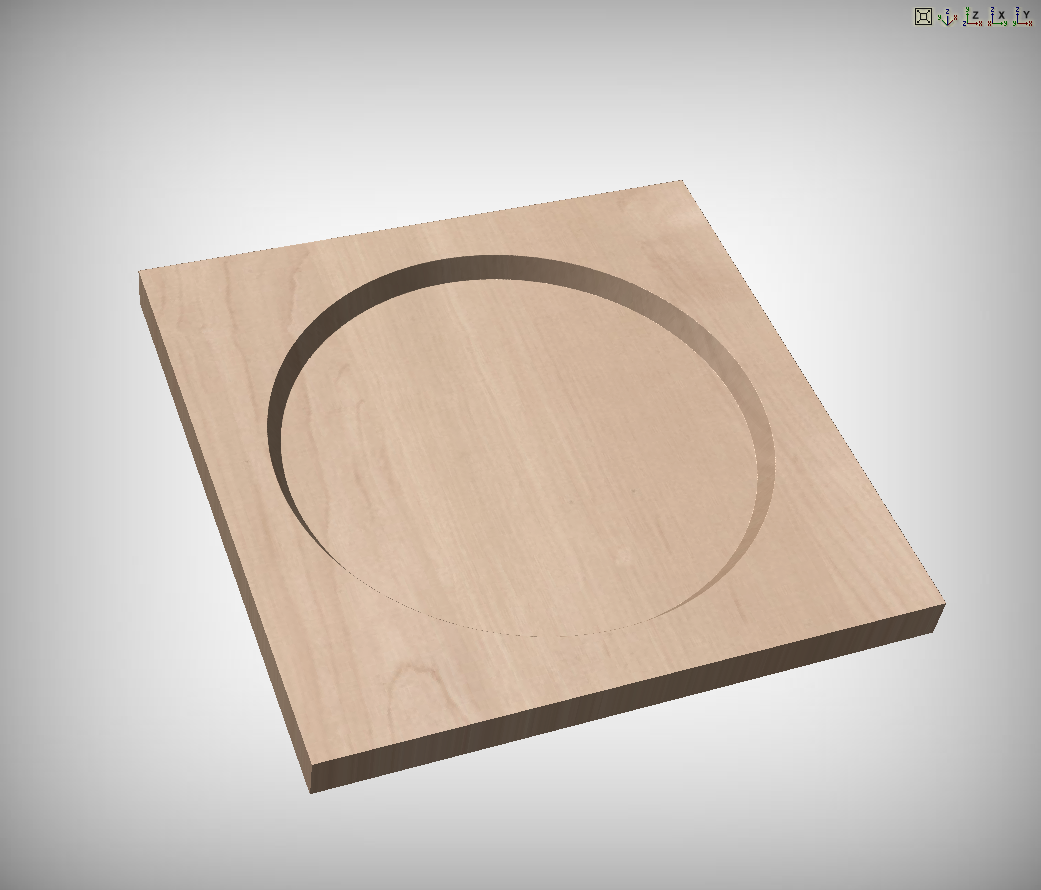
The two options can be used in conjunction with one another to generate different styles of chamfer.
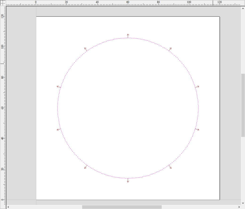
2D Preview
When using the Chamfer toolpath the 2D View will provide immeditate feedback on what the resulting chamfer will look like. Small lines will extend outwards from the selected vector to show where the slope of the chamfer will lie. The arrows on these line indicate the direction of slope. The arrows always point down in the direction of the downwards slope.
Utiliser l'ordre de sélection des vecteurs
Si cette option est cochée, ✓ les vecteurs seront usinés dans l'ordre où vous les avez sélectionnés. Si l'option n'est pas cochée, le programme optimisera l'ordre pour réduire le temps d'usinage.
Propriétés de position et de sélection
Z de sécurité
La hauteur au-dessus de la tâche à laquelle il est possible de déplacer la lame en toute sécurité à une vitesse d'avance rapide / maximale. Cette hauteur peut être modifiée en ouvrant le formulaire de configuration du matériel.
Position de départ
Position de et vers laquelle l'outil se déplacera avant et après l'usinage. Cette dimension peut être modifiée en ouvrant le formulaire de configuration du matériau.
Sélection de vecteur
Cette zone de la page de parcours vous permet de sélectionner automatiquement les vecteurs à usiner en utilisant les propriétés ou la position du vecteur. C'est également la méthode par laquelle vous pouvez créer des modèles de parcours pour réutiliser vos paramètres de parcours sur des projets similaires à l'avenir. Pour plus d'informations, voir les sections Sélecteur de vecteur et Modèles avancés de parcours d'outil.