Laser Picture
Note
The Laser Module is available as a paid-for add-on to the software. The features are not included in your software by deafult. To find out more about the Laser Module go to https://vectric.com/laser-module
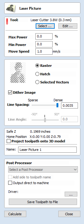
The Laser Picture toolpath uses the laser to etch a copy of the selected bitmap picture into the surface of your material.
Tool Selection
Select Tool
This button opens your database of previously stored laser settings for different jobs and materials. When a setting is selected fromt the database it will be used to populate the key fields in this section. You can subsequenlty modify these values when calculating the laser toolpath. Modifying the settings on this form will not alter the original stored settings within your database.
Power
This value sets the proportion of the maximum laser power from your machines that will be used for this tool path.
Move Speed
This specifies the maximum speed that your machine will move during cutting or engraving moves. The units are determined by the database setting that was originally selected.
No. Passes
The machine can repeat a tool path several times to cut through thicker material. This value sets the maximum depth the machine will attempt to cut with each pass to achieve the final Cut Depth.
Strategy Settings
Raster
Selecting this option will generate a single set of parallel lines, or stripes, across your selected image.
Hatch
This option will create two sets of parallel lines at 90 degrees from one another. This strategy will generally produce a denser image reproduction, but will typcially take twice as long to etch.
Selected
This option will use the selected vectors as the pattern for the toolpath moves. These may be generated using any method of creating vectors, such as the Vector Texture Tool
Dither Image
With this option un-checked, laser power will be changed evenly in response to the lighter and darker areas of your image. Thus your image is reproduced by a range of burnt tones onto the surface of your material using continuously varying laser power. For some materials, however, the burning process tends to produce only two tones - burnt or unburnt - rendering this graduated approach ineffective. For materials with this property an alternative strategy can be used to generate the tonal range using only black dot patterns of differing densities instead - much like old newspaper picture print. This process is called dithering and it can be enabled using this option. In general you should only use this option if the material properties prevent you from using the higher quality true grayscale method.
Line Spacing
This slider adjusts the gap between the raster stripes - tight striping produces a denser image reproduction, but will take a lot longer to etch. The maximum density is set by the Kerf of your laser beam and the most sparse setting is 30 times this value.
Line Angle
Adjust this slider to change the angle of the stripes or hatching used to etch the image. Zero degrees will produce horizontal stripes and ninety degrees, vertical.
Immediate Output
Once calculated, your toolpath is stored in the central Toolpath Tree and can be saved, edited or output to your machine at anytime using the command. In addition though, this form also includes a convenient Immediate Output section that allows you to save or send the most recently calculated toolpath directly from this form without having to close it.
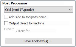
Post Processor
Use this drop-down list to select the post-processor for your machine.
Add side to toolpath name
If you are creating aligned toolpaths for a two-sided part, this option automatically adds the side name to the toolpath name as it is saved or exported to help keep your toolpaths organised.
Output direct to machine
If your post-processor supports direct access to your cnc machine (including machines supported by VTransfer), this option will be available. Selecting this option will bypass saving the toolpath to disk and instead send it straight to the direct output driver.