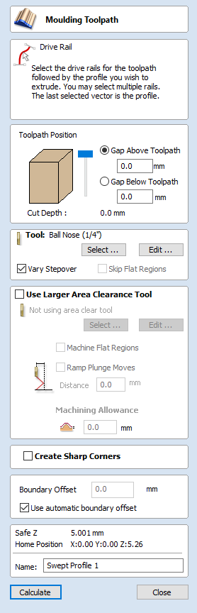
Moulding Toolpath
This icon opens up the Moulding Toolpath Form. This form is used to create a toolpath from a drive
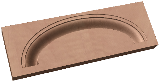
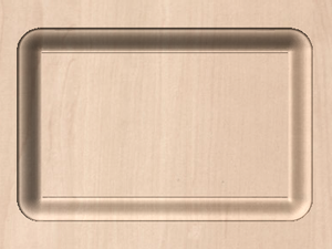
rail and a profile. The result of machining the toolpath is the extrusion of the selected cross-section profile along the pre-selected drive rail. Although strictly speaking the result of this is a 3D shape because it does not use a 3D model it is classified as a 2.5D Toolpath.
Toolpath Position
You now need to determine the toolpath position within the material. The Z Height of the toolpath is determined by the height of the selected cross section. You can interactively position the toolpath by pulling on the slider or you can enter exact values in the edit boxes.
Note
If the cross section you have selected is higher than the material thickness then you will need to change your material thickness in the material setup form to accommodate the profile height, or exit the form and edit the height of the cross section vector you are using to create the Moulding Toolpath to fit within the material block.
Drive Rail Selection
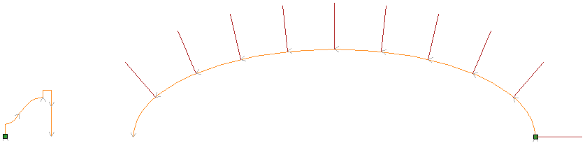
From the 2D view, select the drive rails for the toolpath followed by the profile you wish to extrude.You may select multiple rails.The last selected vector is the Profile that you are extruding.
In the 2D view your rail vector will now be colored orange and will show a green square indicating the start point, along with arrows along the vector showing you the direction.
The direction and start point may not be what you intended, you can change the direction (and start point location on an open vector) by right clicking in the 2D View on the vector and choosing .
The button on the form can be used at any time to empty your current selection; this will deselect the drive rail and if already selected the cross section too. This can be used if you want to change the selection without exiting the form.
Cross Section Selection
After you have chosen your drive rail the next step is to select a cross section that will be swept around the drive rail to create the moulding. The cross section needs to be an open shape in order for this to work.
HoldCtrlTo select a cross section and click on the appropriate vector in 2D View and it will turn orange as with the drive rail, arrows and a green square will appear on it. In addition the drive rail will now have red lines shown on it. These indicate the side of the vector that the shape will be swept along. If this is not correct you will need to reverse the drive rail vector as documented in the previous section.
The arrows and green square on the cross section indicate the direction and the start point. The start point of the cross section will be attached to the start point of the drive rail. If you need to change the start point of the cross section you can do so by selecting the cross section with a right click and choose to Reverse Profile as shown in the image below. Doing this will change the arrow direction and move the green square and also change which end of the cross section is effectively hung on the drive rail when the toolpath is created.
Note
On a closed vector shape, the cross section profile will always hang on the outside of the shape. Therefore, your drive rail vector should always represent the inside edge of the border/frame shape for which you are creating the toolpath. To change the direction in which the toolpath is created, click the Reverse Rail option on a closed vector drive rail.
Selecting a Tool
The next step in this form is to select a tool to finish-cut the moulding shape. This would typically be a ball-nose or tapered ball-nose tool but that may vary depending on the shape you plan to cut. To select a tool use the button to access the Tool Data Base. If the tool you require is already shown as the selected tool, you can use the Edit option to check and/or modify the tool settings for this particular toolpath.
Note
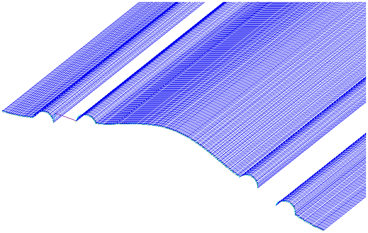
The generated toolpath will follow the shape and direction of drive rail vector. At the end of an open vector it will lift by at least the stepover distance, step over and then come down to the surface again, returning along the vector in the opposite direction, this small lift is designed to avoid leaving connecting marks on the surface of the part and so improve the potential finish quality. On a closed vector after completing a pass the length of the vector it will lift, step-over, return the tool to the profile shape and continue cutting in the same direction - this direction can be reversed by right clicking the drive rail vector and using the Revers Rail option to change the direction of the arrows on the vector.
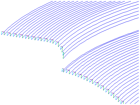
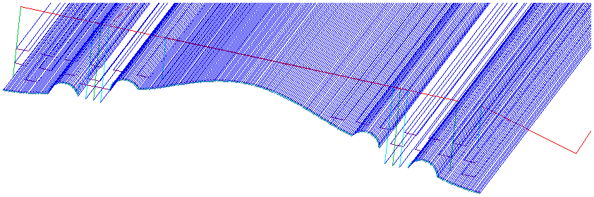
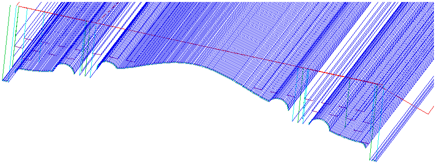
Vary Stepover
Typically the Stepover value specifies the horizontal distance that the tool will step over and this is projected onto the 3D model. Checking ✓ the Vary Step Over option will instead adjust the step over based on the shape of the cross section profile vector rather than just projecting the standard pattern down Z. In cases where there are steeply curved, angled or near vertical edges this should result in passes that are closer together, in most situations this will improve the finish quality but also potentially increase the machining time
Skip Flat Regions
This choice will only become available when the option is checked ✓ to Machine Flat Regions when using the Larger Area Clearance Tool in the next section of the form. When this is active the software will look to identify flat areas of the cross section profile that can be machined with the larger tool. If these regions are detected and Skip Flat Regionsis also checked ✓ then the finish tool will avoid re-machining those flat areas as in most cases they should already have been completely finished by the Larger Area Clearance Toolpath.
Use Larger Area Clearance Tool
If this option is selected, then two tools are used to cut the shape. In effect the Larger Area Clearance Tool is similar to a 3D Z Level Roughing toolpath and would be cut first. It will use the tool parameters to generate multiple depth 2D pockets following the direction of the selected rail to clear away excess material. This should be used if the material is too deep and/or hard to cut directly with your selected finishing tool. As documented above and below using this option with a flat shaped tool can also be very beneficial to the machining time and finish on cross section profile shapes with flat/horizontal regions.
When you use the option to Use Larger Area Clearance Tool, the software will calculate two toolpaths, the first will have [Clear] in its name to differentiate the two, [Clear] being the toolpath associated with the Use Larger Area Clearance Tooland the other, is the finish toolpath using the smaller tool. The [Clear] toolpath should be run first on the machine:
Machine Flat Regions
If this option is checked ✓ then the software will try to detect flat/horizontal areas in the cross section profile. If the specified Larger Area Clearance Tool can fit into these areas then they will be machined as part of the roughing operation. When using a flat tool this should give both a superior finish and also help to reduce the cutting time. Having this option checked ✓ will also allow you to choose the option Skip Flat Regions in the finish tool section which will stop the secondary toolpath from re-cutting these areas.
Note
This option will override the Machining Allowance value in the flat areas of the shape to ensure they are machined to the correct depth and not left with additional material on.
Ramp Plunge Moves
The Larger Area Clearance Tool can be ramped over the specified distance instead of plunging vertically into the part. For some tool types and shapes, this approach can reduce the heat build-up that may damage the cutter and also reduces the load on the spindle and z axis bearings.
Machining Allowance
The machining allowance is a virtual thickness which is added to the moulding profile when the Use Large Area Clearance Tool is calculated. This ensures that the toolpath leaves some extra material on the part cut with a larger tool.
Note
If you have the option selected to Machine Flat Regions the Machining Allowance will only be applied to the other areas of the cross section profile, on the detected flat regions the software will cut down to the actual surface and ignore the Machining Allowance value within those areas ensuring that they are cut to the thickness specified by the cross section profile vector.
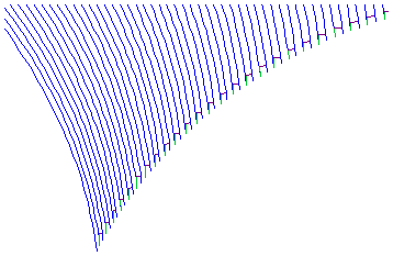
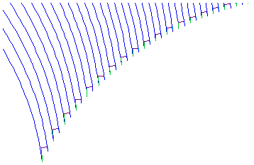
Create Sharp Corners
This option can be checked ✓ when working with rails that have sharp corners, allowing you to force the software to try and emulate these in the Moulding toolpath. Below you can see the effect of checking ✓ this option on a closed vector shape with the standard corners option on the left showing the toolpath rolling around the shape edge and the Sharp Corners option on the left where it has forced mitre style corners in the machined shape.
Boundary Offset
This option can be used to force the toolpath to cut past the edge of the part that is parallel to the drive curve vector. By default the center of the tool will go to the edge of the ends of the selected profile vector as its extruded along the drive rail. It may be desirable to extend this distance to either force the tool down the edge of the profile shape with vertical or steep edges or to ensure the toolpath has gone far enough past the edge to cleanly cutout the final shape with a profile toolpath. The value entered for the Boundary Offset will force the tool past the ends by the specified amount. As such if you want to ensure a vertical or very steep edge at your profile ends is machined you will need to specify a value which is at least the radius of your tool plus a small additional amount (say an additional 10% of the radius). For example if you are using a 0.25 inch (6mm) diameter ball-nose tool for the finish cut then you would specify a minimum of 0.15 inch or 3.6mm (= tool radius + 10%) to ensure the tool would be forced down the edges of your shape. If you wanted to ensure the roughing had also been able to machine these areas then the value should be based on your Larger Area Clearance Tool size instead.
Use automatic boundary offset
When this option is selected, VCarve Pro will calculate the boundary offset to ensure that the tool fully cuts the ends of profile, even if profile ends in vertical/steep edges.