
Aspire User Manual

Version 9
Click on the region of the interface you are interested in:


|


|

|

|

|
Disclaimer
All CNC machines (routing, engraving, and milling) are potentially dangerous and because Vectric Ltd. has no control over how the software described in this manual might be used, Vectric Ltd. or any associated Resellers cannot accept responsibility for any loss or damage to the work piece, machine or any individual, howsoever caused by misusing the software. Extreme care should always be taken and the output from the software thoroughly checked before sending it to a CNC machine.
The information in this manual may be subject to change without any prior notice. The software described in this manual is supplied under the terms and conditions of the software license agreement and may only be used in accordance with the terms of this agreement.
Vectric Ltd.
Web: www.vectric.com
Email: info@vectric.com
Phone: +44 (0) 1527 850 323
Fax: +44 (0) 1527 850 323
Introduction
This manual is designed to provide a comprehensive description of all the functions, tools, menus and icons available within the Aspire software package.
Access this document from Aspire's Help Menu ► Help Contents or from the Aspire folder in the program section of your Windows Start menu.
At the bottom of the page you will see an area with View All Help. This will download all the Help Documentation as a single web page which is useful for searching or if you need to create a paper copy of the documentation.
User Guides, tutorial and training
Please note that this document is a Reference Manual. If you require more guidance, or are still learning how to use Aspire, please ensure that you view the Getting Started Video Tutorials in the Aspire Video Tutorial Browser when starting the software.
Aspire also includes an extensive selection of video tutorials, which are accessible from the Tutorial Video Browser link when application first starts. These tutorials cover every aspect of Aspire's functionality and range in complexity from a beginner's overview, to advanced features and principles. They are intended to be extremely accessible by level of experience or topic and use real-world examples throughout. Videos can be watched online, or installed locally.
We welcome any comments on this manual or the other training material, please email support@vectric.com with your feedback.
The Aspire Logic
Aspire has been developed to allow the production of decorative and artistic dimensional carved parts. As well as drawing and modeling tools, it includes both 2D and 3D machining, along with 3D V-Carving / 3D Engraving to allow a huge variety of jobs to be produced as quickly and easily as possible. The general work flow logic to apply to most jobs is explained in the diagram below:
|
Layout 2D Design Import Vectors Draw Vectors Import Bitmaps |
|
| ⇓ | |
|
Create 3D Components Create shapes from 2D design vectors Create (texture) shapes driectly from bitmaps Import 3D Clipart and models from other CAD systems |
⇖ |
| ⇓ |
Loop through processes until model is finished |
|
Manipulate 3D components to create the 3D composite model using the component tree Change location, depth, size, angle etc. Group and change relationship to other components |
⇗ |
| ⇓ | |
|
Create 2D, 2.5D and 3D toolpath Create or edit vector boundaries for toolpaths Specify tool details for each strategy |
|
| ⇓ | |
|
Preview Final Part Visualize the part as it will actually look Create proof images for customer Check estimate for cutting time |
|
| ⇓ | |
|
Save the CNC Code Save the final cuto file to send to the CNC machine |
Design
Aspire includes drawing and editing tools that allow designs to be created and modified. Functions for vector creation and editing are very easy to use and multiple design elements can also be drawn or imported, scaled, positioned and interactively edited to make a new design. Text can also be created using any TrueType or OpenType fonts installed on your computer, or the single stroke engraving fonts supplied with the software.
Model
Once the 2D design is ready, 3D components can be created from 2D drawings. This will probably involve adding and changing 2D artwork a bit as the 3D design evolves, so Aspire's interface makes the drawing and modeling tools easily accessible.
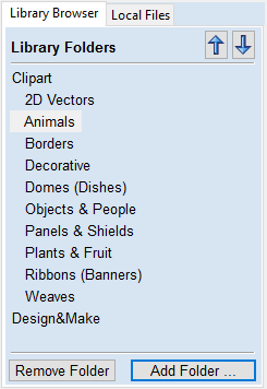
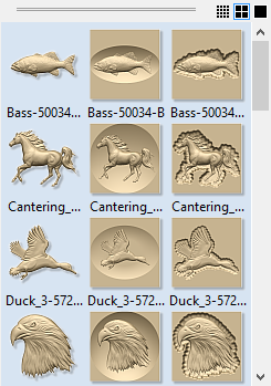
In addition, existing 3D models can be imported to be incorporated into a design, these could be files previously created in Aspire, 3D Clipart that has been purchased and downloaded or models from other CAD design systems in a supported format.
Toolpath
A comprehensive set of 2D, V-Carving, Engraving and 3D toolpath strategies provide you with efficient ways to use your tooling to carve the finished part. This process is usually relatively independent of drawing or modeling (although toolpaths are often created directly from some artwork or 3D composite models). Aspire provides simple interface buttons to toggle screen layout to assist the shift in focus from design to toolpathing.
Output
Finally you can use Aspire's large selection of post-processors to save toolpaths in precisely the format that your particular CNC machine tool requires.
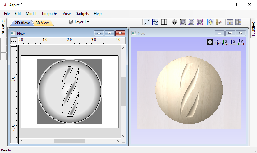
Overview of the Interface
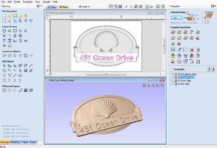
- The Main Menu Bar (the Drop Down Menus) along the top of the screen (File, Edit, Model, Toolpaths, View, Gadgets, Help) provides access to most of the commands available in the software, grouped by function. Click on any of the choices to show a Drop-Down list of the available commands.
-
The Design Panel is on the left side of the screen.
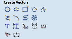
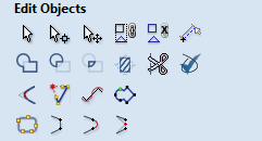
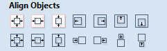
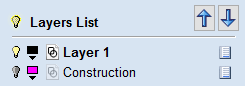
This is where the Drawing, Modeling, Clipart and Layers tab can be accessed and the icons within the tabs to create a design.
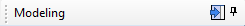
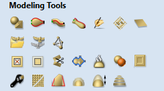
On the Drawing tab you will find the tools for creating, editing, sizing and alignment of vectors. On the modeling tab are all the tools that relate to the management and manipulation of 3D components, as well as the Component Tree, which shows you the 3D components and allows you to define how they are combined to form the final composite 3D model. The 3D Clipart allows simple graphical access to any 3D models that are installed on your computer and the Layers tab allows easy management of layers in the job.
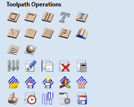
- The Toolpath Tab is on the right side of the screen. The Top section of the toolpaths tab houses all of the icons to create, edit and preview toolpaths. The bottom half shows you toolpaths that you have already created.
- The 2D Design window is where the design is drawn, edited and selected ready for machining. Designs can be imported or created directly in Aspire. This occupies the same area as the 3D View and the display can be toggled between the two using F2 and F3 or the tabs at the top of the window.
- The 3D View is where the composite model, toolpaths and the toolpath preview are displayed.
- If you wish to see the 2D and 3D views simultaneously, or you wish to switch your focus to the Toolpaths tab at a later stage of your design process, you can use the interface layout buttons (accessible in the 2D View Control section on the Drawing Tab) to toggle between the different preset interface layouts.
Managing the Interface
The Drawing, modeling, clipart, Layers and Toolpath tool pages have Auto-Hide / Show behavior which allows them to automatically close when not being used, thus maximizing your working screen area.
Aspire includes two default layouts, one for designing and one for machining, which can automatically and conveniently set the appropriate auto-hide behavior for each of the tools pages. Toggle layout buttons on each of the tools pages allow you to switch the interface as your focus naturally shifts from the design stage to the toolpathing stage of your project.
Accessing Auto-hidden tabs
If a tools page is auto-hidden (because it is currently unpinned, see pinning and unpinning tools pages, below), then it will only appear as a tab at the side of your screen. Move your mouse over these tabs to show the page temporarily. Once you have selected a tool from the page, it will automatically hide itself again.
Pinning and unpinning tools pages
The auto-hide behavior of each tools page can be controlled using the push-pin icons at the top right of the title area of each page.
 |
 |
Pinned Open (auto-hide disabled) |
|
|
Un-pinned (auto-hide enabled) |

Default layout for Design and Toolpaths
Aspire has two default tool page layouts that are designed to assist the usual workflow of design, followed by toolpath creation.