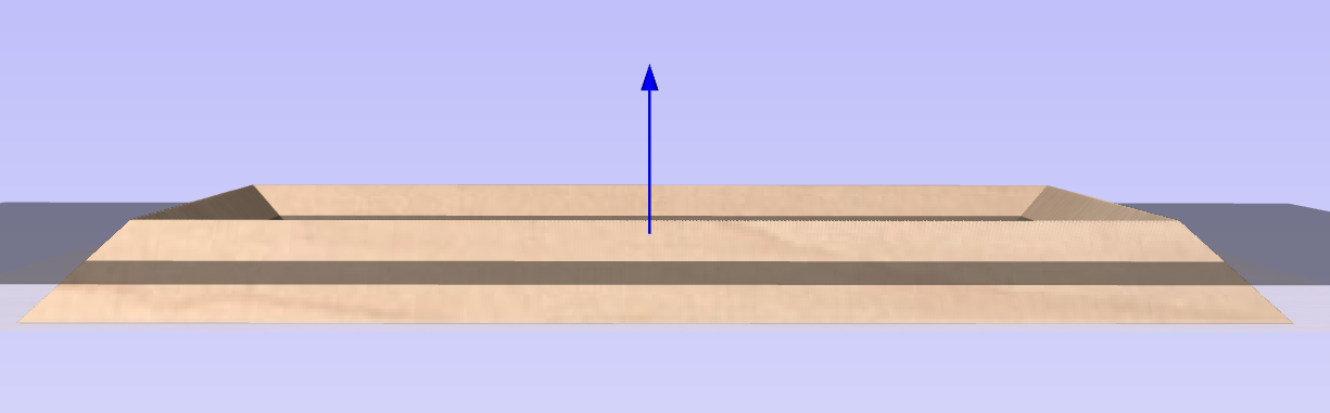
Move Selection
Selected items can be accurately moved and positioned using this option.
Watch this video to see this in action:
 Anchor
The anchor position determines the point on your selected object's bounding box that will be moved to the absolute position entered.
Type of Move
Absolute
In this mode, the X Position and Y Position values will be used to position the object's anchor point directly
Relative
With this option selected, the values entered in the X Position and Y Position fields will incrementally offset the object from its current position, by the distances entered. The Anchor options are not relevant in this mode and so will be disabled.
The keyboard shortcut Mopens the Move form in interactive mode.
Usable In Both Views
This tool can be used in both the 2D and 3D View.
2D View offers a more direct way to view your vectors while 3D Offers more flexability to work with Vectors in 3D Designs and to make use of the Edit Boxes.
Edit Sheet - Single Sided
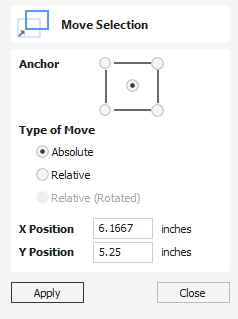
The Job Setup form is displayed whenever a new job is being created, or when the size and position of an existing job is edited.
The size forms may be limited
In most cases a new job represents the size of the material the job will be machined into or at least an area of a larger piece of material which will contain the part which is going to be cut. Clicking OK creates a new empty job, which is drawn as a grey rectangle in the 2D View. Dotted horizontal and vertical Grey lines are drawn in the 2D design window to show where the X0 and Y0 point is positioned.
Job Type
Single Sided job type should be used when design only requires the material to be cut from one side. This is the simplest type of job to design and machine.
Double Sided Job type is useful when it is desired to cut both sides of your material. Aspire allows you to visualise and manage the creation and cutting process of both sides of your design within a single project file.
Rotary job type enables the use of a rotary axis (also called a 4th axis or indexer).Aspire will provide alternative visualisation, simulation and tools appropriate for rotary designs.
Job Size
This section of the form defines the dimensions of the material block you will be using for your project in terms of width (along the X axis), height (along the Y axis) and thickness (along the Z axis).
It also allows you to select which units of measurement you prefer to design in - either inches (Imperial/English) or millimeters (Metric).
Z-Zero Position
Indicates whether the tip of the tool is set off the surface of the material (as shown in the diagram) or off the bed / table of the machine for Z = 0.0.
XY Datum Position
This datum can be set at any corner, or the middle of the job. This represents the location, relative to your design, that will match the machine tool when it is positioned at X0, Y0. While this form is open, a red square is drawn in the 2d view to highlight the datum's position.
Use Offset
This option allows the datum position to be set to a value other than X0, Y0.
Design Scaling
When editing the Job Size parameters of an existing job, this option determines whether any drawings you have already created will be scaled proportionally to match the new job dimensions. If you wish to preserve the existing size of your drawings, even after the job size has changed, leave this option unchecked. With this option checked, your drawings will be re-sized to remain in the same proportion and relative position within your new material extents when you click
Modeling Resolution
This sets the resolution/quality for the 3D model. When working with 3D models a lot of calculation and memory may be required for certain operations. Setting the Resolution allows you to choose the best balance of quality and speed for the part you are working on. The better the resolution quality chosen, the slower the computer will perform.
As this is completely dependent on the particular part you are working on and your computer hardware performance, it is difficult in a document like this to recommend what the setting should be. Generally speaking, the Standard (fastest) setting will be acceptable for the majority of parts that Aspire users make. If the part you are making is going to be relatively large (over 18 inches) but still has small details, you may want to choose a higher Resolution such as High (3 x slower) and for very large parts (over 48 inches) with small details then the Highest (7 x slower) setting may be appropriate.
The reason that the detail of your part needs to be taken into account is that if you were making a part with one large item in it (e.g. a fish) then the standard resolution would be OK but if it was a part with many detailed items in it (e.g. a school of fish) then the High or Highest setting would be better. As previously stated these are extremely general guidelines as on slower/older computers operations with the highest setting may take a long time to calculate.
As the Resolution is applied across your whole work area it is important to set the size of your part to just be big enough to contain the part you plan to carve. It would not be advisable to set your material to be the size of your machine - e.g. 96 x 48 if the part you plan to cut is only 12 x 12 as this would make the resolution in the 12 x 12 area very low.
Appearance
Clicking will pop up a dialog allowing you to set the color or material effect which will be applied to the base 3D model. It is possible to change this at any time and also to apply different colors and materials to different Components using the Component manager. See Preview Toolpaths to learn more about different material settings and adding custom material effects.
Tool Database
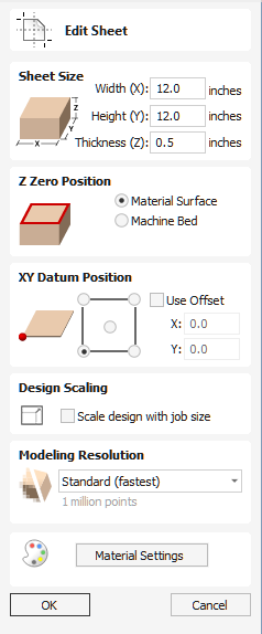
The Tool Database is used to make cutter management and selection very quick and easy, and reduces the possibility of programming jobs with incorrect cut depths and speeds and feeds. It allows pre-defined tools and settings (speeds, feeds, stepover etc.) to be selected from a list for a given machine / material.
The Tool Database can be accessed from the button through the various Toolpath forms. You can open the Toolpaths Tab button or through the Toolpaths menu.
Watch this video to see this in action:
Overview
This is a summary of the main entities and relationships in the database. More details on those will be given in the next sections.
- Tool geometry entities (organised hierarchically in the tree).
- List of Materials (Managed through the Material Management dialog).
- List of Machines (Managed through the Machine Management dialog).
- Cutting Data set for each tool geometry. This includes the Cutting Parameters, and Feeds & Speeds, and are defined per machine / material.
Tool Properties are divided into two categories,
- Tool geometry: This is the physical properties of the tool such as the diameter, tip radius, etc...
- Cutting data: These include the Cutting Parameters and Feeds & Speeds of the tool. These values are defined for a particular material / machine.
Apply Changes
If you modify the Tool database, your changes will only be saved if you click OK. If you exit the Tool Database window using the Cancel button, any changes you have made since opening the Database will be discarded.
Tool Tree
The Tool Tree is located on the left-hand side of the Tool Database. Click on items in the list to see or edit their properties using the Tool Info section of the database window.
You can drag items up and down the list to change their order or drag them inside / outside of groups.
New Tool
Create a new tool with the default name for its type. The tool will be created with the first available type by default, but that can be changed through the Tool Type dropdown to the desired type.
Copy Tool
Duplicate the selected tool geometry or group in the list. If you're copying a tool, it will be copied without its cutting parameters.
The cutting parameters can be subsequently be:
- Copied from the same tool, different material.
- Tool with identical geometry, any material.
- Created with default values.
Delete Tool
Delete the tool as well as all of the cutting data for all machines / materials for which it was defined. If we're deleting a group, this will delete all the tools inside it in the same way.
New Tool Group
Create a new group in the tool database. Tools can then be dragged inside the newly created group. Alternatively, select the group and create a new tool directly under the selected group.
Export Tools
Export an individual tool or an entire group to a tool database file.
Import Tools
A tool database file can be imported into the currently open tool database. You will have 3 options,
- Import: This will simply import the given tools under the selected group (or as a top-level tool / group).
- Merge: This will attempt to merge the incoming tool group hierarchy with the current one (without any regards for selection)
- Overwrite: When it's faced with two similarly nested tools that have the same tool geometry, the cutting data of the incoming tool will overwrite the current tool's cutting data for the active machine / material.
- Without overwriting: A new machine / material will be created to contain the cutting data of the incoming tools.
Tool Definition
When a tool or group is selected in the Tool List, its properties are displayed in the Tool Info section on the right-hand side of the Tool Database.
Name
This will go to the Name Format dialog to edit the name template for this tool type.
The name displayed here is then a result of evaluating the template in the current context (active machine, material and the cutting data defined for those as well as the tool geometry).
The name of a tool group can be defined directly through this dialog.
Tool Type
Various cutters can be specified in the database. Changing the cutter tool type is equivalent to creating a new tool, so all existing data for that tool (if any) may not be applicable anymore.
Notes
The tool notes section simply allows you to save any additional text descriptions, special instructions or relevant information you may require, within your tool definition.
To enter a link into the Note, go to the appropriate page in your Web Browser and select the URL of the page from the Address Bar.
CRTL+C to copy it and then in the Note Field, right click and use the "Paste" option to enter it into the Notes.
To use the HTML Link in the Note Window, hold the CRTL Key and click the link. This will open your computers default Web Browser and load the web page.
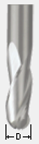
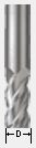
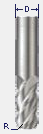
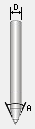
Diameter
The diameter of the tool in either inches or mm. The tool image will indicate where this dimension is taken from.
Number of Flutes
The number of Flutes for the bit. This is particularly useful if you would like to calculate a Chip Load value.
Cutting Data
The cutting data is the set of parameters which can differ between materials and machines. This set of parameters are defined to be per machine per material. The visible set of parameters are the ones for the active material / machine.
Creation / Copying
The cutting data is defined per material per machine. If the data is not defined already for a tool, we create it in a number of ways,
- Create with some default values which you can then change for your purposes.
- Copy from the same tool from a different material: This could be a sensible starting point if the materials have similar / close hardness.
- Copy from a different (identical) tool from the same (or different material)
Pass Depth
The maximum depth of cut the tool can cut. The Pass Depth controls the number of z level passes that are calculated for a toolpath.
For example, creating a pocket 1 inch (25.4 mm) deep using a tool that has a Pass Depth of 0.25 inches (6.35 mm) will result in the toolpath making 4 passes.
This value can be defined per machine / material depending on the machine's rigidity and the material's hardness.
Stepover
The distance the cutter moves over when doing area clearance cutting. For example, when raster machining the cutter will machine along the X axis, stepover in the Y direction and return parallel to the first line of cut. The greater the stepover the faster the job will be machined, but this must be balanced with the material being cut and the tooling being used, to ensure that the tool does not break. Therefore, this property (along with all other Cutting Parameters can be defined per material / machine).
When stepover's greater than 50% of the cutter / tip diameter are used the software automatically adds 'Tail' moves in the corner regions of toolpaths to ensure material is not left on the job for offset based strategies.
When using V-Bit Tools, the Stepover fields automatically change to use the following options.
Final Pass Stepover
The distance the cutter moves over when finish machining and is usually set to be a relatively small distance to produce a smooth surface finish on the job.
Clearance Pass Stepover
Only used when a V-Bit tool is being used to rough machine at multiple Z levels down to a specified flat depth. This stepover can be much larger than the Final Pass Stepover because the tool is only rough machining material away. Increasing the Clearance Pass Stepover will reduce the machining time, but you must be careful to ensure it is not too great for the material being cut.
Spindle Speed
Speed of tool rotation, specified in revolutions per minute.
Feed Rate
The surface cutting rate at which the cutter is moved in the material. The units can be specified in distance per second or minute.
Plunge Rate
The cutting rate at which the cutter is moved vertically into the material or during ramping moves. The units can be specified in distance per second or per minute.
Material / Machine
The Feed rate and Plunge rate you should use will vary depending upon the material being machined and the tooling being used.
Chip Load
This is the calculated Chip Load based on the entered values for the Number of Flutes, Spindle Speed and Feed Rate. This is displayed to conveniently be able to compare it with manufacturer-recommended Chip Load Values.
Maximum Burn Rate
This is the maximum speed at which the tool, when at 100% power, will still burn the material. This value is used for simulation purposes only. It should be calibrated to match your laser and material. A larger value will result in the simulated toolpath appearing darker.
You will need access to the Laser Module to create and simulate laser toolpaths.
Tool Number
This is the number of the tool needed to machine the job. When using a CNC machine with an Automatic Tool Changer (ATC), it is critical that the correct tool required to cut the job is located in the corresponding carousel location.
Per Machine
This parameter only needs to be defined per machine and so is shared between materials (unlike other cutting data parameters which are defined per machine per material).
Material / Machine Management
The cutting parameters / feeds & speeds section of the tool properties is defined for the active machine / material. This allows you to setup your tools with different values for each material or machine and switch between easily depending on the material you're going to use for the current job.
Material
The combo box is used to change active material. This can also be done by going to the Material Management dialog where materials can be added, removed or edited.
Machine
The combo box is used to change active machine. This can also be done by going to the Machine Management dialog where machines can be added, removed or edited.
Online Tool Database
The tool database can be stored and linked to your portal account so that it can be retrieved at any point from a different installation. For this, the software needs to be logged in to the portal account. Then, the database can be uploaded / download on request.
Login
Login to the portal to be able to access the currently stored tool database and / or upload your existing local one.
Download
Download the tool database stored on your portal account to replace your existing local tool database. This can be used for when we know there is a more up-to-date version online. You will also be prompted to update if that is the case.
Upload
When changes have been made to the tool database, this will upload it to the portal account so that it can be downloaded from any other location linked to the same portal account.
Remote Tool Database
Using the Right most Icon you can load a Remote Tool Database from a URL link supplied to you. More on this in the Remote Tool Database page.
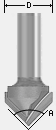
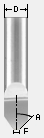
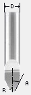
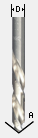
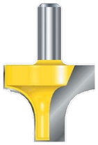
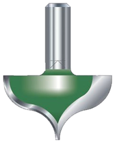
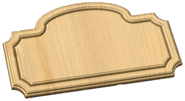
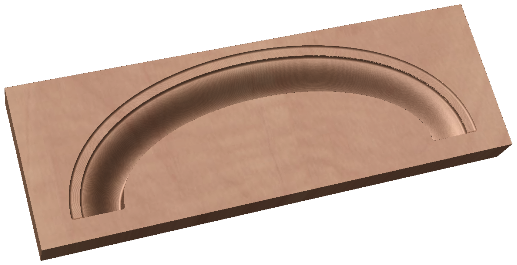
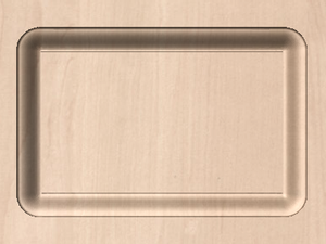
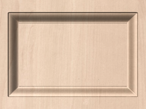
Using Form Cutters
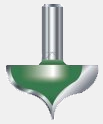
Form Cutters can be added to the Tool Database so that industry standard Ogee and Round-over type cutters, plus user definable custom shapes can be used for edge profiling and decorative carving.
Examples of these types of cutters and the kind of cuts they can be used for are shown in the images below:
Custom Form Cutters
Before opening the tool database, draw to exact scale the Right side of the cutter geometry in the 2D Window Use the Node Editing tools to create the arcs and curves etc.
Geometry
Only draw the Right-hand side of the cutter geometry to the correct size and scale as shown in the image above. The shape can be a combination of Lines, Arcs and Bezier spans.
Select the vector, then open the Tool Database dialog and create a new tool. Then, set its type to Form Tool.
The selected geometry will be imported and a profile displayed in the window. Give the Cutter a meaningful name. Enter the cutting parameters - speeds and feeds etc for the various materials you've got defined.
Click the Apply / OK button to save the new cutter into the database list so it can be used at any time.
Laser Module
Note
The Laser Module is available as a paid-for add-on to the software. The features are not included by default.
The Laser Module is a paid add-on for Aspire which adds the following additional functionality:
- The ability to create Laser Cut and Fill Toolpaths
- The ability to create Laser Picture Toolpaths
- The ability to simulate a Laser Toolpath
If you have a licence code for the laser module then it can be installed by using the Help > Enter Licence Code menu item. Enter the licence code into the Licence Code field. The Licensed To field does not need to be changed.
You will have to restart you software to enable the features.
The Laser Cut - Fill Toolpath
Laser Cut - Fill Toolpath is used for cutting out shapes or marking areas.
Cut-outs can take into account the kerf, or width, of the laser beam to maintain the precise internal or external size the selected vector shapes. Shapes can also be filled with stripes or hatching to create simple shading effects.
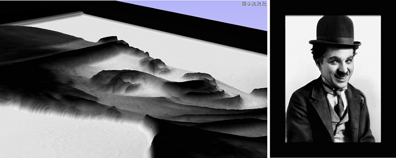
The Laser Picture Toolpath
The Laser Picture toolpath uses the laser and through varying the power of the laser etches a copy of the selected bitmap onto the surface of your material.
Simulating Laser Toolpaths
Like all other toolpaths the laser toolpaths can be simulated. However, in the case of laser toolpaths, the simulation does not remove any material but instead marks the surface of the current simulation model. This marking is meant to simulate the charring of the material when scorched by the laser.
Due to the many combinations of laser, power, material and feed rate, it will be necessary to calibrate the simulation so that the simulation output matches the real-world results. This calibration can be done by modifying the Maximum Burn Rate property of a given tool. This is the maximum speed at which the tool, when at 100% power, will still burn the material. This means that a greater value will result in the simulated toolpath appearing darker. This value can be set in the Tool Database. We suggest you cut a sample file with the material and power settings that you would typically use and then adjust the Maximum Burn Rate so that the simulation matches your achieved results.
Adapting a post-processor for Lasers
Introduction
The Laser Module enables both new tool types to represent lasers in the tool database, and also new laser specific strategies.
The laser module now provides independent records and variables for laser tools and toolpaths. Because these outputs have been separated from conventional router control, for most machines and controllers it is often possible to create a single Post Processor to work seamlessly with router or laser toolpaths, but please note that you may still need to ensure that the physical configuration of your machine is changed depending on the toolpath type.
Previous Post Processors will not work correctly with the Laser Module
Please note that many conversion kit manufacturers provided Vectric Post Processors before the release of the Laser Module. These used workarounds to allow some router toolpath strategies, such as profiling, to be used with a laser head. Post Processors created without explicit support for the additional features documented here will not work correctly.
There are generally 4 areas that need to be modified in a conventional Post Processor to extend it for Laser toolpath support.
- Add support for a new
Powervariable, which will be used by the new laser strategies. - Add new laser-specific Post Processor Blocks to format laser toolpaths correctly for your machine and controller.
- Modify any existing Post Processor Blocks to ensure independent power and laser-specific behaviour.
- Add a flag to tell Vectric's software that this post now supports laser toolpath strategies.
The following sections deal with each area in turn and an example using the GRBL gcode controller is provided. These examples are from the grbl (mm & inch) post processor provided by default with Vectric's software.
Power Variable
Vectric's software will output the power setting for a laser toolpath in the range of 1-100%. We need to add a new variable to show how to format this setting for your particular controller. This is also the opportunity to scale the raw percentage value to the numerical range that your controller requires.
Example
For GRBL-based controllers, the power setting for a laser is typically aliased to the gcode spindle speed control command 'S'. In laser mode, the controller will respond to a spindle speed control change by adjusting the power of the laser instead. Although it can be set within the controller, the default setting for the maximum expected 'S' value - or laser power - is 1000.
For GRBL, therefore, we need to format the POWER variable to be a gcode 'S' command and scale its output value by a factor of ten so that it is in the range of 1 to 1000 (instead of the default 1-100).
The variable entry in the Post Processor reads:
VAR POWER = [P|C|S|1.0|10.0]
To break this entry down in plain English, we are saying that the POWER output from our toolpath should be used everywhere in our subsequent post definition file where we have the the variable [P]. But we should only only output a command as the POWER value changes (C). We will replace the [P] variable locations in our our toolpath output with the command 'S' (S). The power value should be formatted as a whole number with no decimal points (1.0) and should be multiplied from its default by a factor of 10.
New Laser Post Processor Blocks
To allow Laser control, there are new Post Processor Blocks available in the Post Processor. These are:
JET_TOOL_ON- Output whenever the toolpath needs the laser onJET_TOOL_POWER- Output whenever the toolpath needs the laser power to changeJET_TOOL_OFF- Output whenever the toolpath needs the laser off
Example
In our GRBL example we haved added the 3 new block types. For turning the laser on, GRBL makes use of gcode M4 command (normally intended for spindle direction, but 're-used' by GRBL for laser support ). We can now make use of our POWER variable, defined above as [P], to provide the required power value. The JET_TOOL_ON block is thus:
+---------------------------------------------------
+ Commands output when the jet is turned on
+---------------------------------------------------
begin JET_TOOL_ON
"M4[P]"
For turning the Laser off GRBL makes use of the gcode M5 command:
+---------------------------------------------------
+ Commands output when the jet is turned off
+---------------------------------------------------
begin JET_TOOL_OFF
"M5"
Finally for setting the power itself then for GRBL we just output the power:
+---------------------------------------------------
+ Commands output when the jet power is changed
+---------------------------------------------------
begin JET_TOOL_POWER
"[P]"
Modify Existing Blocks
We also want it to be the case that when we perform a feed move then we also output the power, so to do this we update the FEED_MOVE blocks to include [P].
We have to do that for all of the different feed move types.
In addition, we need to avoid plunge moves occurring when the laser is on. For conventional milling or routing, we need the spindle to be on before a plunge move, but for a laser it is crucial that we only turn it on after we have moved to the correct Z level (this problem manifests as 'overburn' at the beginning of each toolpath segement). To ensure that we can correctly separate these requirements, we may need to remove any spindle commands from plunge moves, or other block types (some may have them in the header, for example) and break these out into explicit SPINDLE_ON & PLUNGE_MOVE blocks. This will ensure that these moves are only made for non-laser toolpath strategies and in the correct sequence.
Example
For GRBL this is a simple addition to the end of the feed move statement:
+---------------------------------------------------
+ Commands output for feed rate moves
+---------------------------------------------------
begin FEED_MOVE
"G1[X][Y][Z][P]"
Remember that we set our POWER variable to only output on change (C) so note that in the output for feed moves at constant power, only an initial, changing, power command will be included. For some controllers, the number of commands that can be processed is a limiting factor on the speed of toolpath and for laser images, in particular, this can be mitigated somewhat by not sending uneccessary commands whenever possible.
For the separate GRBL spindle and plunge control the blocks are:
+---------------------------------------------------
+ Command output after the header to switch spindle on
+---------------------------------------------------
begin SPINDLE_ON
"[S]M3"
+---------------------------------------------------
+ Commands output for the plunge move
+---------------------------------------------------
begin PLUNGE_MOVE
"G1[X][Y][Z][F]"
You'll note that GRBL uses the M3 to control the router or mill. Also note that the plunge move requires the ability to move the machine in X & Y in order to support ramping.
Explicitly Mark the Post Processor as Laser Capable
Lastly a Post Processor will require the new Global File Statement LASER_SUPPORT="YES" added to be available for selection as a Laser Post Processor within the software.
This is only added to Post Processors for general use once the Post Processor has recieved complete testing by the creator.
Example
LASER_SUPPORT = "YES"
SketchUp Files
SketchUp files with a .SKP extension (see www.sketchup.com) can be imported as 2D data suitable for machining into a Aspire job using the File ► Import Vectors... command from the menu bar or the import vectors icon on the Drawing tab. To import data from a SketchUp file you must already have created or opened a job to import the data into.
As a SketchUp model is usually a 3D representation of the part, the SketchUp importer offers a number of options to allow you to start manufacturing the model.
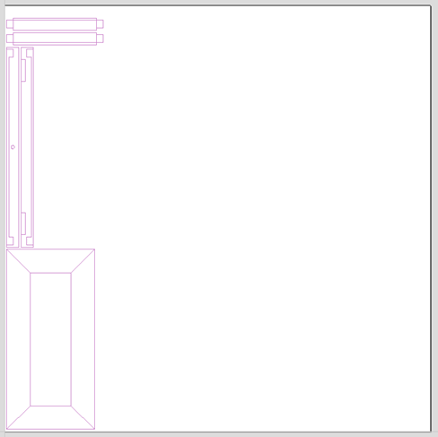
We will illustrate the two main choices for how the model will be imported using the SketchUp model shown to the left.
The model shown in the screenshots is a cabinet constructed by following the instructions in the Fine Woodworking 'Google SketchUp guide for Woodworkers: The Basics' DVD which is available via the Fine Woodworking site at www.finewoodworking.com. Vectric have no affiliation with Fine Woodworking, we are just using screenshots of the model constructed while following their tutorials to illustrate the process of importing a SketchUp model.
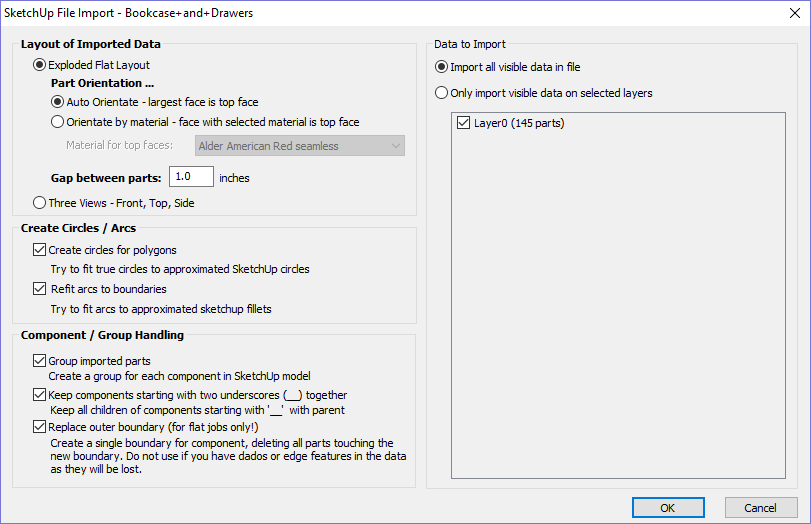
Layout of Imported Data
In the first section there are two main choices for how the data from the model will be imported, 'Exploded Flat Layout' and 'Three Views - Front, Top, Side' as shown below.
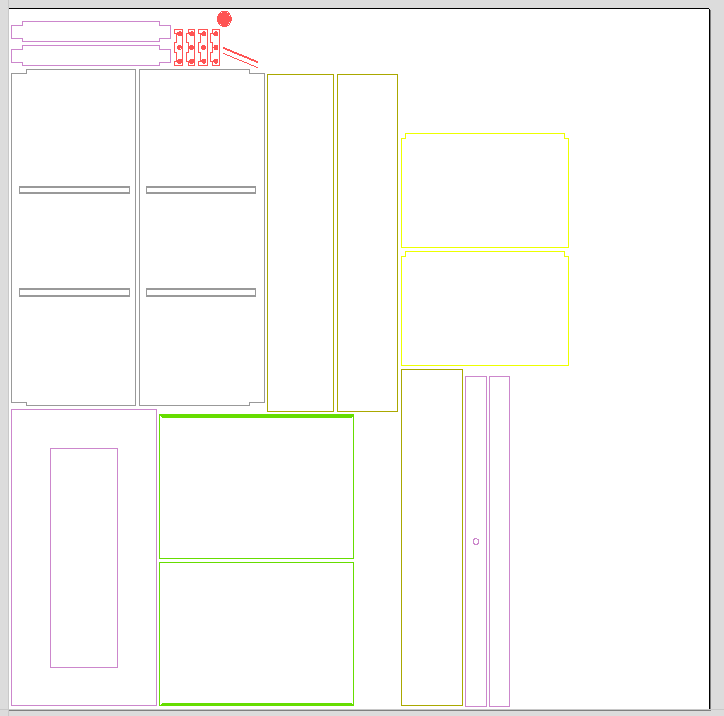
Exploded Flat Layout
This option will take each component in the model and orientate it flat ready for machining.
Once this option is selected a number of sub-options also become available.
Part Orientation
This section controls what Aspire considers to be the 'top' face of each part.
Auto Orientate
If this option is selected, for each part in the model, the 'face' with the largest area based on its outer perimeter (i.e. ignoring holes etc.) is considered to be the 'top' face and the part is automatically rotated so that this face is facing upwards in Z. This strategy works very well for models which are to be manufactured from sheet goods where there are no features on particular faces which need to be on the 'top' (such as pockets).
Orientate by material
This option allows the user to control more explicitly the orientation of each part in the model. Within SketchUp the user can 'paint' the face of each component/group with a material/color of their choice to indicate which face will be orientated on top when the model is imported. When this option is selected simply chose the material which has been used to indicate the top face from the drop down list. If a part is found in the model which does not have a face with the specified material, that part will be oriented by making the largest face the top.
Gap between parts
This field lets the user specify the gap between parts when they are first imported. After importing, the nesting functions within Aspirecan be used to layout the parts with more control and across multiple sheets
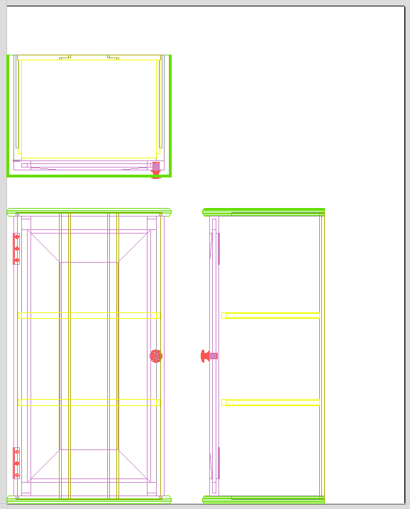
Three Views - Front, Top, Side
This option will create an 'engineering drawing' style layout of the SketchUp model as shown in the screenshot below.
The size of the model is preserved and it is relatively simple to pick up dimensions for parts you are going to manufacture from the various views. The colors of the lines you see are taken from the colors of the original SketchUp layers the various parts of the model are on.
Create Circles / Arcs
SketchUp does not maintain true arc or circle information for the boundaries of its parts. This is a problem when it comes to machining as the 'polygonal' SketchUp representation can give very poor machining results. For this reason, Aspire offers the option to refit circles and arcs to imported data.
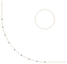
The screenshot above left shows the results of importing a part with a filleted corner and hole with these options unchecked. The 'fillet' is made up of a series of straight line segments and the circular 'hole' is actually a polygon made up of straight lines.
The screen shot above right shows the same part imported with both these options checked ✓. The 'fillet' now consists of a single smooth arc and the circular 'hole' now also consists of arcs rather than straight line segments. Both these features will machine more cleanly in this form.
Data to Import
A SketchUp model will often contain parts that you do not wish to machine (such as hinges, knobs etc.) or data which will be cut from different thicknesses of material and hence different parts need to be imported into different Aspire jobs. To allow control over what is imported you can choose to only import parts of the model which are on particular layers using this section of the dialog.
To only import data from selected layers, choose the 'import visible data on selected layers' option and click the check box next to each layer to indicate if you want to import data from that layer. Note that the number of parts on each layer is displayed next to the layer name.
It is very easy to assign different parts of the model to different layers within SketchUp to help with the import process into Aspire. The screenshot below shows the result of only importing data on the 'Door' layer from the example.
Component / Group Handling
This section of the form allows advanced handling of how 'parts' within the SketchUp model are identified and treated on import.
Group imported parts
This option is normally selected for all but the simplest models as it allows each 'part' of the model to be selected, moved and nested easily after import. You will need to ungroup the imported data after nesting etc. to allow individual features to be machined. By default, Aspire will treat each SketchUp group / component as a single part UNLESS it contains other groups or components within it, in which case each lowest level group / component will be treated as a separate part.
Items which you retain in groups can be ungrouped at any time in the usual ways.
If the right-click menu-option to Ungroup back onto original object layers is used (which is the default option when using the icon or shortcut U) then the software will place the ungrouped items back onto the original layers they were created on in SketchUp.
Keep components starting with two underscores (__) together
If you have a complex model which contain 'parts' which are made up of other groups / components, you will need to do some work on your model to identify these parts for Aspire. The way this is done is by setting the name of the groups / components that you wish to be treated as a single part to start with__ (two underscore characters). For example, if you had a model of a car and you wanted the wheels / tires / hub nuts to be treated as a single part even though the Tire, Wheel and other parts were separate components, you would group the parts together and name them something like __WheelAssembly in SketchUp. When this model was imported, and Aspire reached the group/component with a name starting with __ it would treat all subsequent child objects of that object as being the same part.
Replace outer boundary (for flat jobs only!)
There is a style of 'building' with SketchUp where individual 'parts' are made up of several components 'butted' against each other. The screenshot below shows such a component.

This object is made up of many smaller components representing the tabs on the top, the connectors at the end and the support at the bottom as shown below.
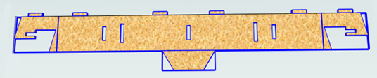
Although when can treat this as a single 'part' when imported by starting its name with __ (two underscores), the imported part is still going to be difficult to machine. The screenshot below shows the part imported into Aspire without the 'Replace outer boundary' option checked ✓. The part in the image has been ungrouped and the central vector selected.
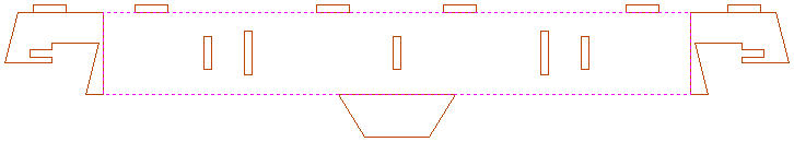
As you can see, the outer boundary is made up of separate segments for each 'feature'. Aspire does have the ability to create an outer boundary for vectors but this can be time consuming if it has to be done manually. If the 'Replace outer boundary' option is checked, ✓ for every part Aspire will try to create a single outer boundary and delete all the vectors which were part of this boundary. The screenshot below shows the result of importing the same data with this option checked, ✓ this time the part has been ungrouped and the outer vector selected.
This data is now ready to be machined directly. It is important to understand the limitations of this option. It can be substantially slower. Creating robust boundaries for each part can consume a lot of processing power. Any feature which shares an edge with the boundary will be deleted. If the tabs on the top of this part were to have been machined 'thinner', this approach would not have been suitable as the bottom edge of the tabs has been removed.
IMPORTANT
The new features will help a lot of SketchUp users dramatically reduce the time it takes to go from a SketchUp design to a machinable part using Vectric Software. It is important to understand though that while these options provide a useful set of tools, in many cases there will still be additional editing required to ensure the part is ready to toolpath. Understanding the options and how they work will allow the part to be designed in SketchUp with these in mind and therefore help to minimize the time to machine once the data is imported.
Note
Sketchup files will only open in the same bit version you are running e.g. A file saved in a 32 bit version of Sketchup will only open up in a 32 bit version of the software.
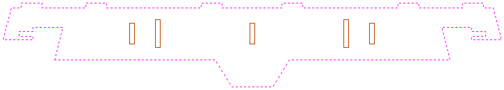
Moulding Toolpath
This icon opens up the Moulding Toolpath Form. This form is used to create a toolpath from a drive
rail and a profile. The result of machining the toolpath is the extrusion of the selected cross-section profile along the pre-selected drive rail. Although strictly speaking the result of this is a 3D shape because it does not use a 3D model it is classified as a 2.5D Toolpath.
Watch this video to see this in action:
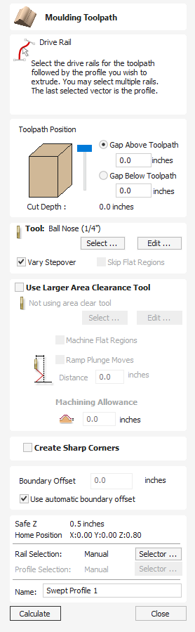
Toolpath Position
You now need to determine the toolpath position within the material. The Z Height of the toolpath is determined by the height of the selected cross section. You can interactively position the toolpath by pulling on the slider or you can enter exact values in the edit boxes.
Note
If the cross section you have selected is higher than the material thickness then you will need to change your material thickness in the material setup form to accommodate the profile height, or exit the form and edit the height of the cross section vector you are using to create the Moulding Toolpath to fit within the material block.
Drive Rail Selection
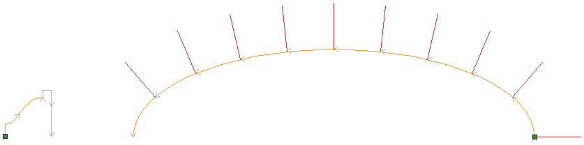
From the 2D view, select the drive rails for the toolpath followed by the profile you wish to extrude.You may select multiple rails.The last selected vector is the Profile that you are extruding.
In the 2D view your rail vector will now be colored orange and will show a green square indicating the start point, along with arrows along the vector showing you the direction.
The direction and start point may not be what you intended, you can change the direction (and start point location on an open vector) by right clicking in the 2D View on the vector and choosing .
The button on the form can be used at any time to empty your current selection; this will deselect the drive rail and if already selected the cross section too. This can be used if you want to change the selection without exiting the form.
Cross Section Selection
After you have chosen your drive rail the next step is to select a cross section that will be swept around the drive rail to create the moulding. The cross section needs to be an open shape in order for this to work.
HoldCtrlTo select a cross section and click on the appropriate vector in 2D View and it will turn orange as with the drive rail, arrows and a green square will appear on it. In addition the drive rail will now have red lines shown on it. These indicate the side of the vector that the shape will be swept along. If this is not correct you will need to reverse the drive rail vector as documented in the previous section.
The arrows and green square on the cross section indicate the direction and the start point. The start point of the cross section will be attached to the start point of the drive rail. If you need to change the start point of the cross section you can do so by selecting the cross section with a right click and choose to Reverse Profile as shown in the image below. Doing this will change the arrow direction and move the green square and also change which end of the cross section is effectively hung on the drive rail when the toolpath is created.
Note
On a closed vector shape, the cross section profile will always hang on the outside of the shape. Therefore, your drive rail vector should always represent the inside edge of the border/frame shape for which you are creating the toolpath. To change the direction in which the toolpath is created, click the Reverse Rail option on a closed vector drive rail.
Selecting a Tool
The next step in this form is to select a tool to finish-cut the moulding shape. This would typically be a ball-nose or tapered ball-nose tool but that may vary depending on the shape you plan to cut. To select a tool use the button to access the Tool Data Base. If the tool you require is already shown as the selected tool, you can use the Edit option to check and/or modify the tool settings for this particular toolpath.
Note
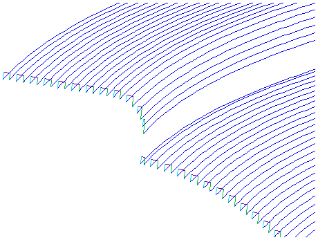
The generated toolpath will follow the shape and direction of drive rail vector. At the end of an open vector it will lift by at least the stepover distance, step over and then come down to the surface again, returning along the vector in the opposite direction, this small lift is designed to avoid leaving connecting marks on the surface of the part and so improve the potential finish quality. On a closed vector after completing a pass the length of the vector it will lift, step-over, return the tool to the profile shape and continue cutting in the same direction - this direction can be reversed by right clicking the drive rail vector and using the Revers Rail option to change the direction of the arrows on the vector.
Vary Stepover
Typically the Stepover value specifies the horizontal distance that the tool will step over and this is projected onto the 3D model. Checking ✓ the Vary Step Over option will instead adjust the step over based on the shape of the cross section profile vector rather than just projecting the standard pattern down Z. In cases where there are steeply curved, angled or near vertical edges this should result in passes that are closer together, in most situations this will improve the finish quality but also potentially increase the machining time
Skip Flat Regions
This choice will only become available when the option is checked ✓ to Machine Flat Regions when using the Larger Area Clearance Tool in the next section of the form. When this is active the software will look to identify flat areas of the cross section profile that can be machined with the larger tool. If these regions are detected and Skip Flat Regionsis also checked ✓ then the finish tool will avoid re-machining those flat areas as in most cases they should already have been completely finished by the Larger Area Clearance Toolpath.
Use Larger Area Clearance Tool
If this option is selected, then two tools are used to cut the shape. In effect the Larger Area Clearance Tool is similar to a 3D Z Level Roughing toolpath and would be cut first. It will use the tool parameters to generate multiple depth 2D pockets following the direction of the selected rail to clear away excess material. This should be used if the material is too deep and/or hard to cut directly with your selected finishing tool. As documented above and below using this option with a flat shaped tool can also be very beneficial to the machining time and finish on cross section profile shapes with flat/horizontal regions.
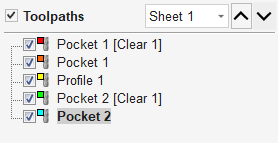
When you use the option to Use Larger Area Clearance Tool, the software will calculate two toolpaths, the first will have [Clear] in its name to differentiate the two, [Clear] being the toolpath associated with the Use Larger Area Clearance Tooland the other, is the finish toolpath using the smaller tool. The [Clear] toolpath should be run first on the machine:
Machine Flat Regions
If this option is checked ✓ then the software will try to detect flat/horizontal areas in the cross section profile. If the specified Larger Area Clearance Tool can fit into these areas then they will be machined as part of the roughing operation. When using a flat tool this should give both a superior finish and also help to reduce the cutting time. Having this option checked ✓ will also allow you to choose the option Skip Flat Regions in the finish tool section which will stop the secondary toolpath from re-cutting these areas.
Note
This option will override the Machining Allowance value in the flat areas of the shape to ensure they are machined to the correct depth and not left with additional material on.
Ramp Plunge Moves
The Larger Area Clearance Tool can be ramped over the specified distance instead of plunging vertically into the part. For some tool types and shapes, this approach can reduce the heat build-up that may damage the cutter and also reduces the load on the spindle and z axis bearings.
Machining Allowance
The machining allowance is a virtual thickness which is added to the moulding profile when the Use Large Area Clearance Tool is calculated. This ensures that the toolpath leaves some extra material on the part cut with a larger tool.
Note
If you have the option selected to Machine Flat Regions the Machining Allowance will only be applied to the other areas of the cross section profile, on the detected flat regions the software will cut down to the actual surface and ignore the Machining Allowance value within those areas ensuring that they are cut to the thickness specified by the cross section profile vector.
Create Sharp Corners
This option can be checked ✓ when working with rails that have sharp corners, allowing you to force the software to try and emulate these in the Moulding toolpath. Below you can see the effect of checking ✓ this option on a closed vector shape with the standard corners option on the left showing the toolpath rolling around the shape edge and the Sharp Corners option on the left where it has forced mitre style corners in the machined shape.
Boundary Offset
This option can be used to force the toolpath to cut past the edge of the part that is parallel to the drive curve vector. By default the center of the tool will go to the edge of the ends of the selected profile vector as its extruded along the drive rail. It may be desirable to extend this distance to either force the tool down the edge of the profile shape with vertical or steep edges or to ensure the toolpath has gone far enough past the edge to cleanly cutout the final shape with a profile toolpath. The value entered for the Boundary Offset will force the tool past the ends by the specified amount. As such if you want to ensure a vertical or very steep edge at your profile ends is machined you will need to specify a value which is at least the radius of your tool plus a small additional amount (say an additional 10% of the radius). For example if you are using a 0.25 inch (6mm) diameter ball-nose tool for the finish cut then you would specify a minimum of 0.15 inch or 3.6mm (= tool radius + 10%) to ensure the tool would be forced down the edges of your shape. If you wanted to ensure the roughing had also been able to machine these areas then the value should be based on your Larger Area Clearance Tool size instead.
Use automatic boundary offset
When this option is selected, Aspire will calculate the boundary offset to ensure that the tool fully cuts the ends of profile, even if profile ends in vertical/steep edges.
Position and Selection Properties
Safe Z
The height above the job at which it is safe to move the cutter at rapid / max feed rate. This dimension can be changed by opening the Material Setup form.
Home Position
Position from and to that the tool will travel before and after machining. This dimension can be changed by opening the Material Setup form.
Vector Selection
This area of the toolpath page allows you to automatically select vectors to machine using the vector's properties or position. It is also the method by which you can create Toolpath Templates to re-use your toolpath settings on similar projects in the future. For more information, see the sections Vector Selector and Advanced Toolpath Templates.
Name
The name of the toolpath can be entered or the default name can be used.
Automatic Vector Selection
Like many of the other toolpaths the Moulding toolpath can use an automatic vector selector (see here for more details). In the case of the Moulding toolpath there are two separate selectors, one for the rail and one for the profile. Both work as any other selector does and will be saved with any toolpath template that uses them.
V-Carve Toolpath
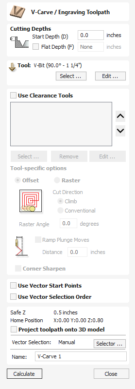
This icon opens the V-Carving Toolpath form which is used to specify the type of carving required, details, cutting parameters and name for the toolpath.
V-Carving uses a constant angled cutter that's moved at flowing variable depth to create a 3D carved effect on the job. The software automatically calculates a path defined by the combination of the angle of the tool specified and the width and shape of the vectors being machined.
Watch this video to see this in action:
Cutting Depths
Start Depth (D) specifies the depth at which the V-Carving toolpath is calculated, allowing V-Carving / Engraving to be machined inside a pocket region. When cutting directly into the surface of a job the Start Depth will usually be 0.0. If the V-Carving / engraving is going to be machined into the bottom of a pocket or stepped region, the depth of the pocket / step must be entered. For example, to carve or engrave into the bottom of a 0.5 inch deep pocket, the Start Depth = 0.5 inches
Start Depth (D)
Start Depth (D) specifies the depth at which the V-Carving toolpath is calculated, allowing V-Carving / Engraving to be machined inside a pocket region. When cutting directly into the surface of a job the Start Depth will usually be 0.0. If the V-Carving / engraving is going to be machined into the bottom of a pocket or stepped region, the depth of the pocket / step must be entered. For example, to carve or engrave into the bottom of a 0.5 inch deep pocket, the Start Depth = 0.5 inches
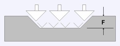
Flat Depth (F)
Checking ✓ this option limits the depth that the tool(s) will machine to, and is used for Flat Bottomed Carving and Engraving.
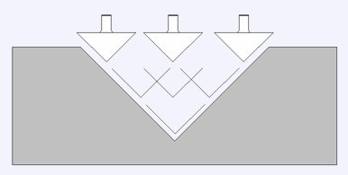
When No Flat Depth is specified the toolpath will be calculated to carve or engrave to full depth as shown below. Multiple z level passes will be automatically calculated where the tool needs to cut deeper than its Pass Depth specified in the Tool Database
No Flat Depth
Flat Depth
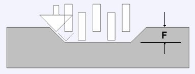
Flat Depth Using 2 Tools
Tool
Clicking the button opens the Tool Database from which the required V-Carving or Engraving Tool can be selected. See the section on the Tool Database for more information on this.
Clicking the button opens the Edit Tool form which allows the cutting parameters for the selected tool to be modified, without changing the master information in the database. Note that Ball Nose tools can also be used to V-Carve designs.
Use Clearance Tools
Check ✓ this option if you wish to use End Mill, Ball Nose or Engraving cutters to machine the large open regions of a design. If no tool is selected here but Flat Depth is specified then the selected V-Carving tool will be used to clear the flat areas as well as for the V-Carving. All the tools in this section will leave an allowance for the V-Carving tool. Subject to this, the first tool in the list will remove as much material as it can, whereas subsequent tools will only machine areas the previous tools could not fit. The order of the tools in the list should match the order they will be run on the machine.
Clicking the button opens the Tool Database from which the required clearance tool can be selected and added to the list.
Clicking the button will remove the selected tool from the list.
Clicking the button opens the Edit Tool form which allows the cutting parameters for the selected tool to be modified, without changing the master information in the database.
Clicking the up and down arrow buttons will move the selected tool up and down the list respectively.
Clearance Tool Options
The strategy used to clear the material, either Offset or Raster, can be chosen for the first clearance toolpath. In the case of Raster, a Raster Angle can be entered.
The cutting direction, either Climb or Conventional, can be selected for each clearance tool.
Checking ✓ Ramp Plunge Moves applies ramping to the plunge moves of the clearance tool.
The above options are the same as those found on the Pocketing form.
Checking ✓ Corner Sharpen will raise the selected Engraving tool to fit the smaller tool tip into narrower regions. This option is available for a tool positioned second or later in the list.
Use Vector Start Points
If this option is checked ✓, the start point of the profile and offset toolpath segments will be as close as possible to the start point of the corresponding boundary vector. Otherwise this is left up to the program.
Use Vector Selection Order
If this option is checked ✓, the vectors will be machined in the order you selected them. If the option is not checked the program will optimize the order to reduce machining time.
Position and Selection Properties
Safe Z
The height above the job at which it is safe to move the cutter at rapid / max feed rate. This dimension can be changed by opening the Material Setup form.
Home Position
Position from and to that the tool will travel before and after machining. This dimension can be changed by opening the Material Setup form.
Project toolpath onto 3D Model
This option is only available if a 3D model has been defined. If this option is checked, ✓ after the toolpath has been calculated, it will be projected (or 'dropped') down in Z onto the surface of the 3D model. The depth of the original toolpath below the surface of the material will be used as the projected depth below the surface of the model.
Note:
When a toolpath is projected onto the 3D model, its depth is limited so that it does not exceed the bottom of the material.
Vector Selection
This area of the toolpath page allows you to automatically select vectors to machine using the vector's properties or position. It is also the method by which you can create Toolpath Templates to re-use your toolpath settings on similar projects in the future. For more information, see the sections Vector Selector and Advanced Toolpath Templates.
Name
The name of the toolpath can be entered or the default name can be used.
Join Open Vectors
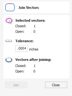
The icons to join and close vectors are located under the Edit Vectors section of the Drawing Tab.
Open vectors are automatically identified and closed or joined to other vectors where the end points lie within the user definable tolerance.
Watch this video to see this in action:
Usable In Both Views
This tool can be used in both the 2D and 3D View.
2D View offers a more direct way to view your vectors while 3D Offers more flexability to work with Vectors in 3D Designs and to make use of the Edit Boxes.
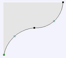
Distort Object
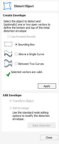
This tool allows you to bend and flex a vector or component by manipulating a distortion envelope using standard node editing tools. You can select one or more vectors or components and then use one of the three different tool modes to create your initial distortion envelope.
Multiple Objects
You can distort several vectors or components at once but you cannot distort a mixture of vectors and components together in a single operation.
Once the distortion envelope has been created, you can use the node editing tools to add or edit its nodes and spans. As you alter the shape of the envelope the associated object will be distorted to reflect the changes.
Watch this video to see this in action:
Layers
When distorting a selection of objects which fall on different layers, the result will be created on the layer of the first object in the selection.
Use Rotated Bounds
This option is only supported if you only have one object selected to distort. It makes use of the local rotation of the object as shown in the Selection Tool.
When this option is ticked,
- The initial distortion envelope is created along the transformed bounds of the selected object.
- When distorting along a curve (or two), the object is distorted on the curve in its local transformation. This is useful if you're distorting a rotated object onto a rotated curve, for example.
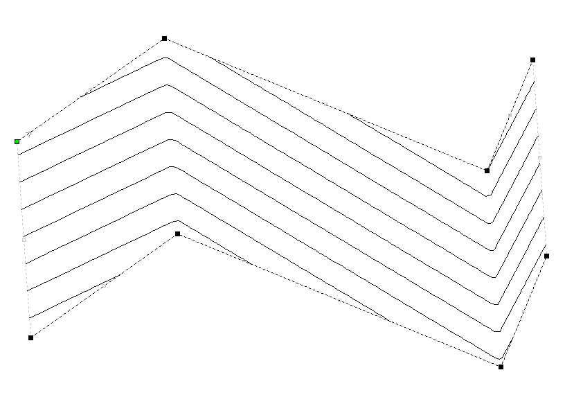
Bounding Box Distortion
This option is available if you have a selection of vectors or components (Note that you cannot mix vectors and components in this mode). It creates a distortion envelope based on the closest bounding box that can be drawn around your selection. Thus the resulting envelope is always initially a rectangle, comprising four line spans and a node at each corner. Using the normal node editing tools, however, you can modify this envelope as much as you like and the shape within it will be distorted accordingly.
Along a Single Curve
This option is only available if the last item in your selection is an open vector that can be used to define a curve, above which the other selected objects will be distorted. The distorted object can comprise one or more vectors or one or more components, but not both.
Using this option, you will usually end up with your objects bent to match the curve in your original selection. The distortion curve itself is left unchanged by this operation.
Between Two Curves
This option will become available if the last two objects in the current selection are open vectors, between which the other objects can be distorted.
Baking Distortion into an Object
Once an object has been distorted, node editing will always relate to the object's distortion envelope. If you wish to edit a distorted vector directly again, you will first need to permanently apply the distortion to the shape.
If you select an object that already has a distortion envelope while in the Distort Object tool, the button will be available. Clicking this button will permanently apply your current distortion and you will then be able to either distort the object again (with new settings), or node edit the shape directly.
Baking Components
If you try to use this tool to modify multiple, grouped or distorted components you will first be prompted to 'bake' your selection components into a single object. For more information on what this means, please see the section Baking Components.
Usable In Both Views
This tool can be used in both the 2D and 3D View.
2D View offers a more direct way to view your vectors while 3D Offers more flexability to work with Vectors in 3D Designs and to make use of the Edit Boxes.
Redo Operation
Clicking this option steps forward through design steps that have been Undone using the Undo command (see above) to get back to stage that the user started using the Undo function.
12. Advanced - Modelling 3D Rotary Projects
Elaborating 2D designs with 3D clipart pieces
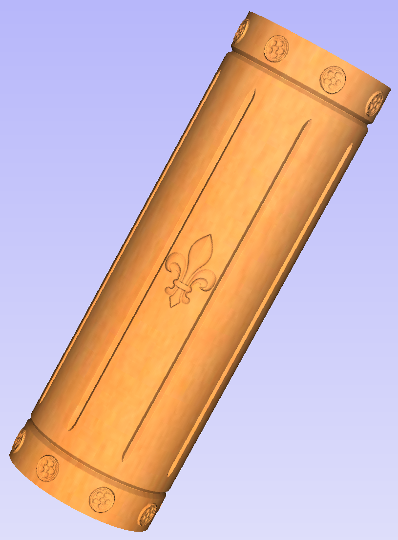
This section will present how to add 3D clipart to basic fluted column presented in Simple rotary modelling using 2D toolpaths.
A simple way to start with 3D rotary models is to use add pieces of decorative clipart that is provided with Aspire. This process is very similar to adding clipart to single - or double - sided project, however there are some additional considerations that are specific to wrapped rotary machining.
To start, switch to the Clipart tab. Then choose a piece of clipart and drag and drop it into the workspace. Aspirewill show following message:
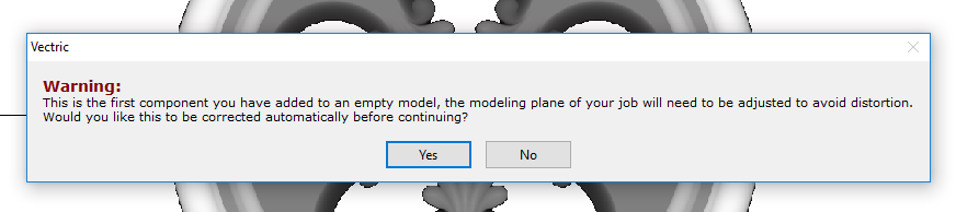
To understand this message, we need to consider the flat view of our model, after importing the clipart. Flat view can be accessed by clicking Auto Wrapping button.
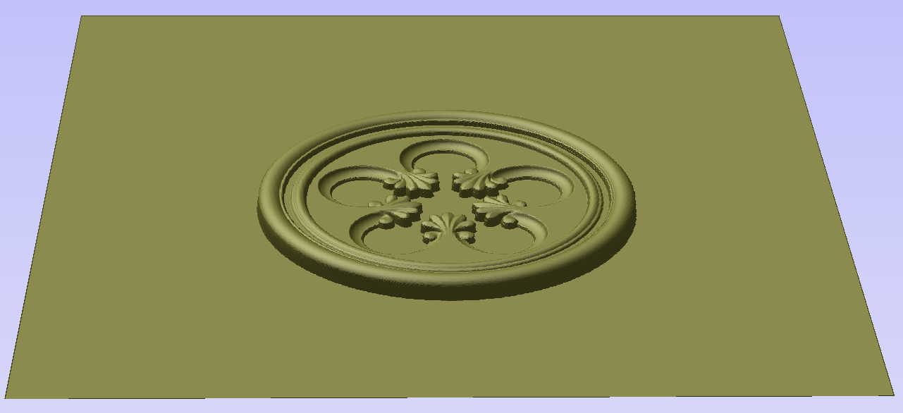
As can be seen, the model contains only the selected decorative piece on the flat plane. Although the column is obviously a cylindrical solid, so far we only used 2D toolpaths to carve details on the surface of cylinder. So the fact that machined piece is a cylindrical solid, derives only from fact that the blank is a cylindrical solid itself. Aspireallows the 3D model to also describe a solid body.
In this example the intent is to only place a decorative piece on the surface, rather than define body of the column. Aspirecan see that we did not model a body and we are placing a piece of clipart, that is likely to be placed at the surface. By responding 'Yes' to the message we can confirm that it is our intent to use the component to decorate a surface.
Note
The above message is only displayed when the 3D model is empty. Regardless of user choice, this message will not be displayed again for this project.
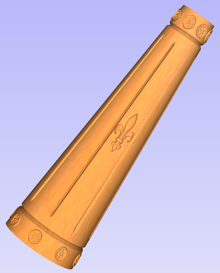
More clipart can be placed as desired. Then the 3D view can be inspected. Once design is finished it is time to create toolpaths. In order to create 3D roughing toolpath, use the 3D Roughing Toolpath. Then create 3D finishing toolpath, using 3D Finish Toolpath. Select settings that are most appropriate for given application, while remembering which axis is rotating. The choice of axis may be particularly important if rotation axis speed is slower than linear axis.
In this example the decorative clipart that was added was not recessed. That means that after 3D machining the flat areas around clipart will be recessed due to clipart 'standing out' of the flat surface. Therefore existing 2D toolpaths needs to be projected. This can be accomplished by selecting Project toolpath onto 3D model option and recalculating the toolpaths.
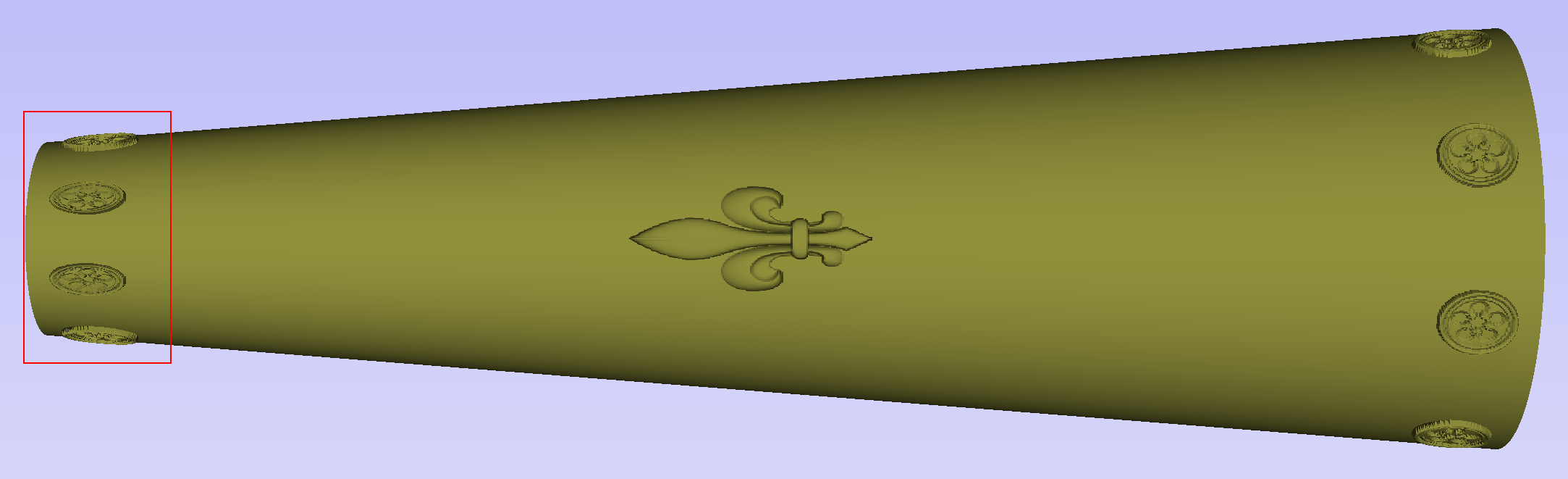
Making a tapered column
This section will explain how to make a tapered column by modifying the basic design from previous section.
So far only the surface details were modelled. In order to make a tapered shape, we need to model 'body' of the shape in addition to surface details. For that purpose, zero plane component can be used. It is added automatically for rotary jobs.
Double-click the zero plane component to open Component Properties. Enter 0.8 in the Base Height box. Select Tilt option. Click Set button in Tilt section, then switch to 2D view and then click in the middle left and then in the middle right. Set the angle to 3 degrees.
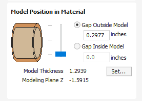
Since the modelling plane was adjusted for placing component on the surface, it needs to be adjusted again, so the component body is not 'inflated'. To do that open the Material Setup form. Adjust modelling plane by moving the slider down, until the Gap Inside Model is 0.
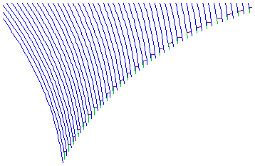
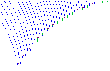
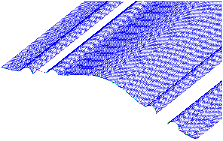
After modelling a tapered shape, the 3D model of column will have a desired shape. However clipart pieces in the narrower parts have been distorted, as can be seen below. To fix that, one needs to stretch the components in the wrapped dimension, to compensate for distortion.
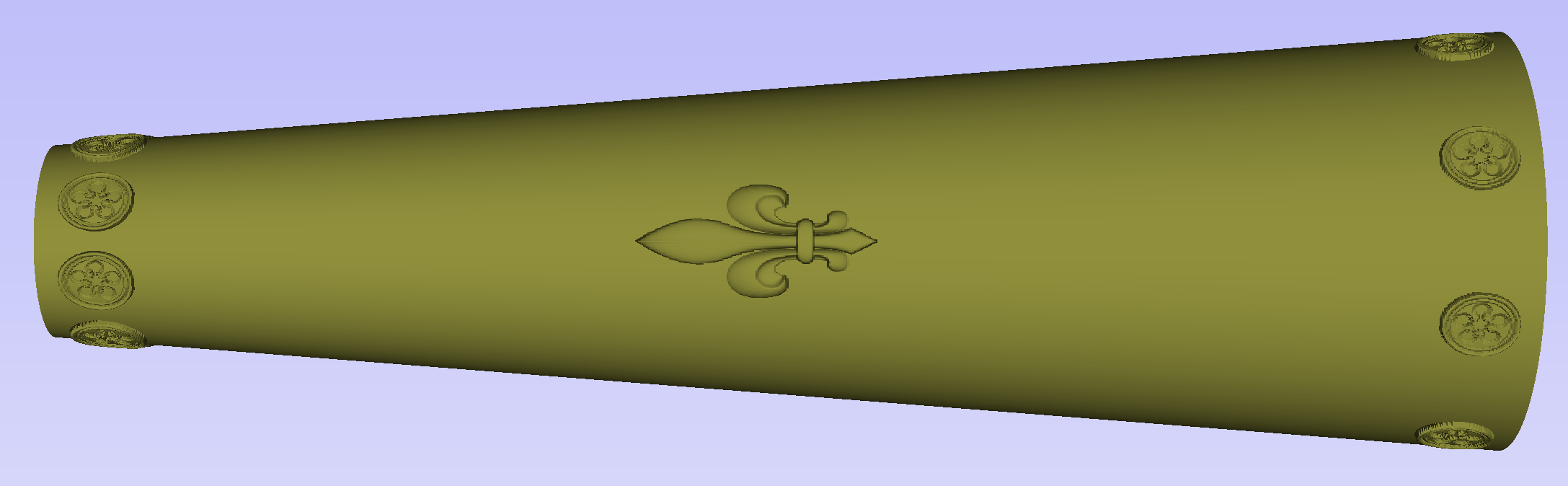
The distortion that has been demonstrated above, applies also to toolpaths. That means that wrapped toolpaths will match flat toolpaths only at the surface of the blank. The closer to the rotation axis (i.e. deeper) the toolpath is, the more it will be 'compressed'. This fact have a profound implication for 3D toolpaths. Consider the example shown below.
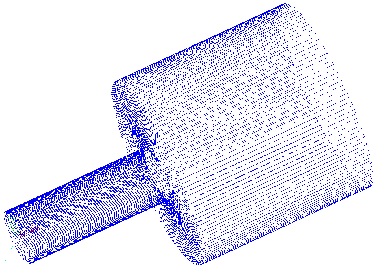
As can be seen if there is substantial difference in diameter in different parts of model, generating one 3D toolpath for whole model will result in wrapped toolpath being overly compressed. Thus it is usually better to create boundaries of regions with significantly different diameter and generate separate toolpaths using correct settings for each diameter.
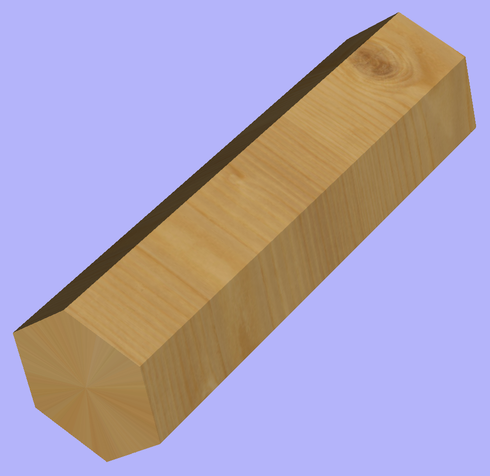
Modelling turned shapes
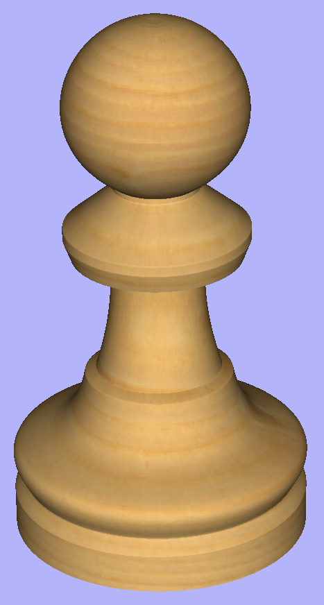
This section will present a basic technique for creating turned shapes.
Modelling turned shapes is quite easy. It requires a vector representing a profile of the desired shape and a Two Rail Sweep tool.
To start, create a new rotary job. Then either draw a profile using available drawing tools or import profile vector. This example used a chess pawn profile, as can be seen below.
Open the Two Rail Sweep tool. When the rotary job is created, the software inserts a special layer called '2Rail Sweep Rails'. It contains two blue lines on the sides of the job, that are perpendicular to the rotation axis.
Select both of those rails and click the Use Selection button. The rails will then be highlighted. Then select the profile vector and click apply. Inspect the 3D view to verify the results.
Modelling cross section
This section will explain how to model desired shape using Vector Unwrapper.
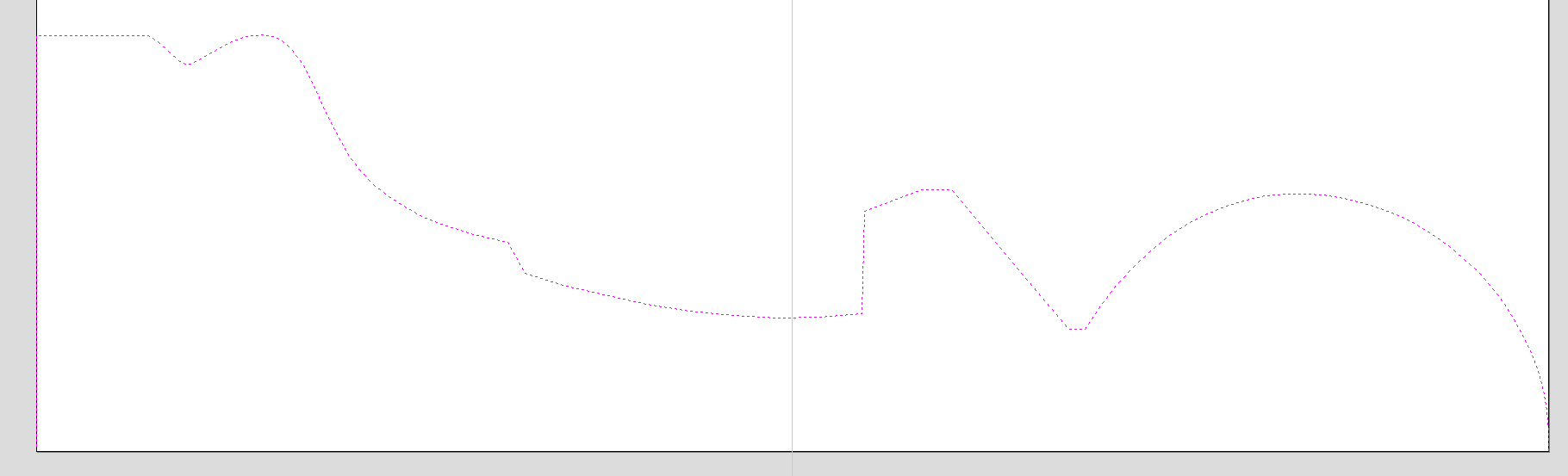
The Vector Unwrapper is useful when rather than modelling a profile along the rotation axis, it is more intuitive to specify a desired cross section. The tool transforms a vector, representing a cross section, into a profile vector that can be subsequently used with Two Rail Sweep tool.
Suppose we would like to create a hexagonal-shaped column. Let's start by creating a new rotary job. In this example job has a diameter of 6 inches and is 20 inches long. X axis is the rotation axis and Z origin has been placed on the cylinder axis.
We need to create a hexagon using Draw Polygon tool. This vector will serve as a cross section and can be placed anywhere in the 2D view. In this example the material block diameter is 6 inches, so the radius of the shape cannot exceed 3 inches.
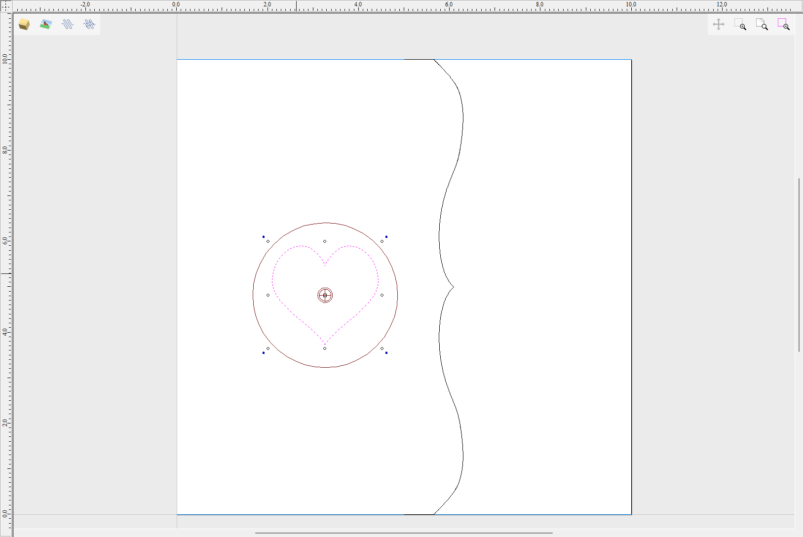
When the shape is created, select it and open Vector Unwrapper. The tool will display a crosshair in place where the rotation axis is crossing the profile and a circle with the diameter of the material block. This will help you determine whether the shape with such cross profile will fit in current material block.
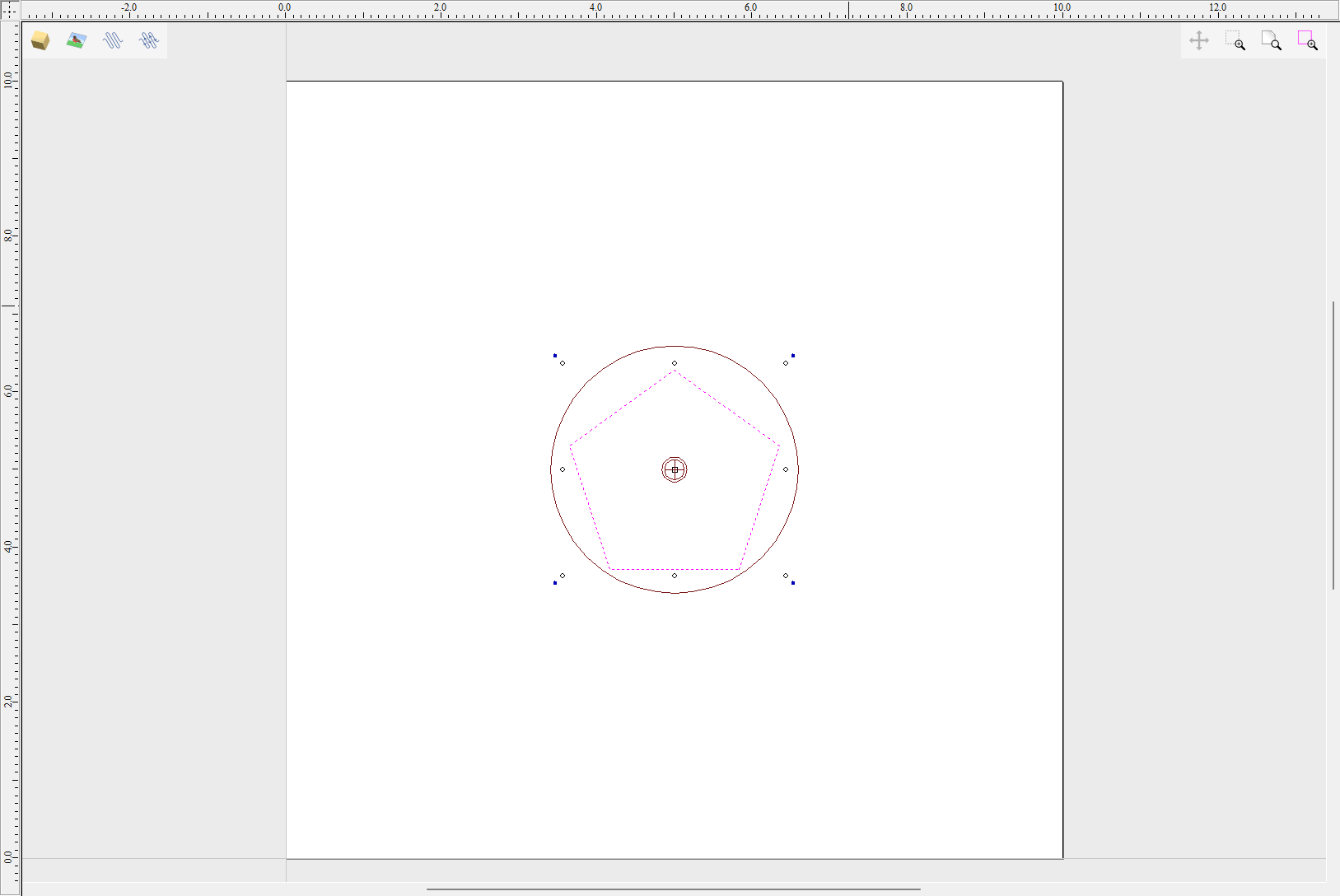
In this example, the Use Center of contour option was used. That means that rotation axis will be placed in the centre of vector's bounding box. One can also tick Simplify unwrapped vectors option to fit bezier curves, instead of using series of very short line segments. After apply is pressed, the unwrapped version of the selected cross section will be created, as have been shown below.
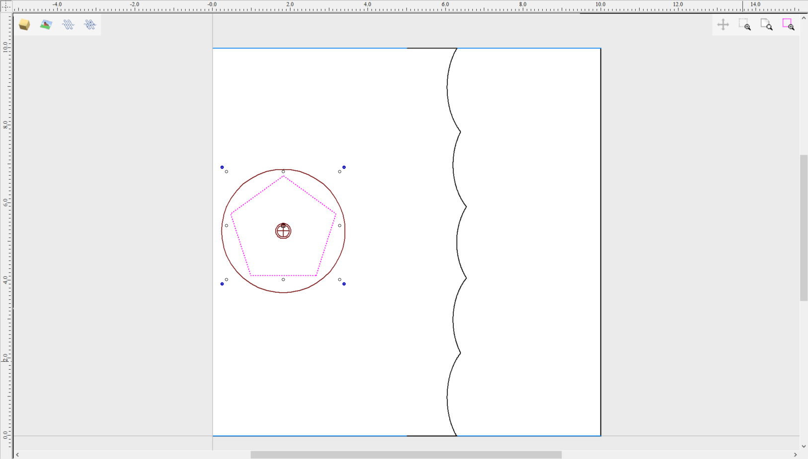
This example shows the unwrapped vector for a cylinder rotating around the X axis. If your rotary axis is aligned along Y the unwrapped vector will be horizontal. It is worth noting that unwrapped profile have 'legs' on each end. Those are needed to ensure that correct height will be used in the next step.
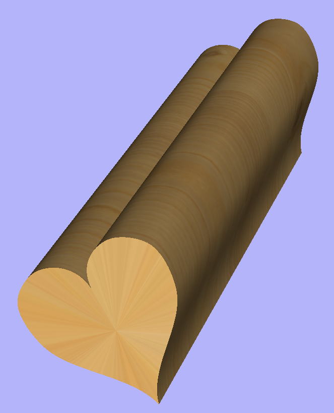
The tool automatically creates layer called 'Unwrapped Vectors Drive Rails' on which it places two blue line vectors on job sides, parallel to the rotation axis. In order to extrude the profile, open the Two Rail Sweep tool. Then select top and then bottom rail (left and right when Y axis is rotation axis) and confirm selection by clicking Use Selection button. The rails will now be highlighted. Now click on unwrapped vector and press apply. The 3D view will show a hexagonal column, that can be seen at the beginning of this section.
Modeling Plane
The desired cross-section will only be achieved if modelling plane is positioned in cylinder centre. That means that Gap Inside Model is reported as 0 in Material Setup form. Otherwise the resulting model will have incorrect diameter and the cross section will become rounded.
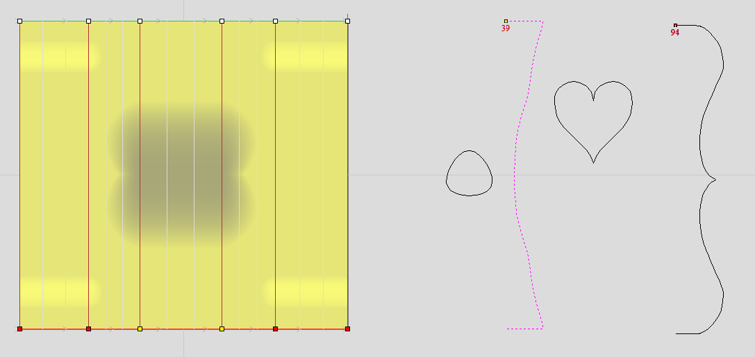
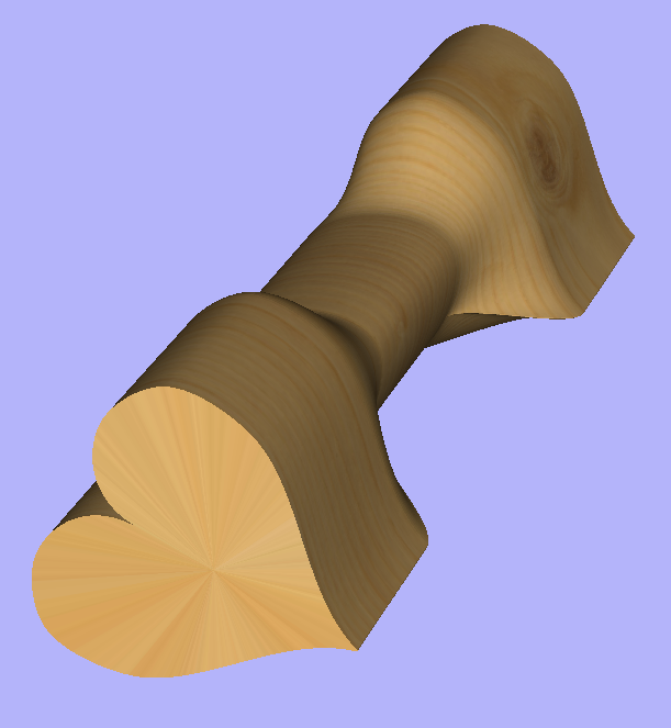
The Vector unwrapper is not restricted to simple shapes. In principle it is always possible to use convex shapes and certain concave shapes. The example below shows a heart profile unwrapped.
If cross section in question is concave, one could imagine straight line starting in the center of the shape and touching a point on the boundary. If the second points keeps travelling along the boundary and each line is not crossing another point on the boundary, then it is possible to use this cross section. If the line does cross more than one point on the boundary, this part of the cross section will not be represented correctly.
All the examples so far used a single cross section. However it is also possible to use multiple cross sections.
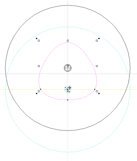
Let's take another cross section and open Vector Unwrapper. Then drag the rotation axis handle a bit down from the center. If snapping is enabled, it can be used to help position the rotation center, as can be seen below.
Once we have another unwrapped cross section, it is possible to use both during Two Rail Sweep. For example unwrapped heart profile can be placed twice on the left and twice on the right. The second unwrapped profile can be placed twice in the middle. Such arrangement may result in shape morphing, as can be seen below.
Text Selection
The Text Selection tool allows the user to adjust kerning, line spacing and bending the text on an arc. The text will be displayed as magenta lines with 2 Green handles in the middle for arching the text.
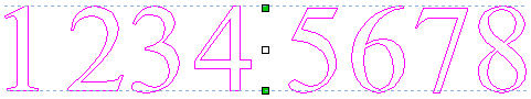
If the selected text was placed on a curve the handles will not appear, as such text cannot be arched.
Letter Kerning
The interactive kerning and line spacing cursor is shown when placed between letters or lines:

The interactive letter kerning allows default text to be modified so that adjacent pairs of letters sit more naturally together. A typical example is shown above where the capital letters W A V are placed next to each other and the default space is excessive.
Place the cursor between 2 letters and click the Left mouse button to close the gap.
Holding the Shift key and clicking the Left mouse button moves the characters apart.
Holding the Ctrl key when kerning doubles the distance each letter moves on each click.
Holding Shift and Ctrl keys together and clicking the Left mouse button moves the letters closer together in larger increments.
Holding down altwith any of the above combinations will apply the kerning changes between every pair of letters on the line.
Line Spacing
Line spacing can be modified by placing the Edit Text cursor between lines. It will change to the line spacing cursor:

Clicking Left mouse button will move the adjacent lines of text closer together.
Holding the Shift key and clicking the Left mouse button will move the lines apart.
Holding the Ctrl key doubles the distance each line moves on each mouse click.
Holding the Shift and Ctrl keys together and clicking the Left mouse button moves the lines apart in larger increments.
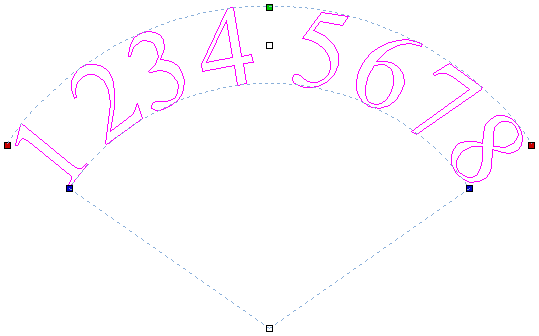
Text Arching
The interactive rotation and movement cursor is displayed when the cursor is placed over either of the Green Handles to indicate that the text can be arced either Upwards or Downwards:


Click and Drag the Bottom Green box to arc the text Downwards.
Click and Drag the Top Green box to arc the text Upwards.
The text can easily be dragged back into the horizontal position again.
After arcing text, additional Red and Blue handles are displayed for Rotating and Moving the text.
Moving
There are two white handles for moving the text, one in the middle of the text, and one in the center of the arc, though that may be off-screen for very shallow arcs.
Rotating
Clicking and dragging the Red boxes rotates the text around the center point of the arc.
Holding the Ctrl key forces the rotation to be in 15° increments. This allows the text to be positioned exactly on the horizontal or vertical quadrants, even after it may have been moved slightly.
Changing arc radius
Clicking and dragging the Blue boxes changes the radius without moving the arc center.
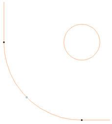
Circular Copy
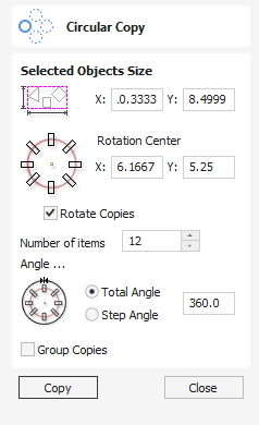
This tool will automatically create a repeating pattern by making copies of the selected object and positioning them around a full or partial circle. The number of copies to be made can be entered directly.
Watch this video to see this in action:
Selected Objects Size
Reports the current size of the selection that you are intending to copy. This is for information only, but the values can be selected, copied and pasted to use in other calculations.
Rotation Center
This is the absolute XY coordinate around which the objects will be rotated when copied and pasted. The default Rotation point is the middle of the selection. You can set the rotation center coordinates explicitly using the X and Y edit boxes on this form or by clicking the selected geometry to show the transform grips, then double-clicking the center one to show the pivot-point and dragging the Pivot Point handle associated with the selection in the 2D View:
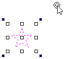
Rotate Copies
This option controls whether the copied objects are each rotated as they are placed around the circle, as shown in the diagrams below. If this option is selected, each copy is rotated according to its position on the circle. If the option is not selected then each copy maintains the orientation of the originally selected object.

Angle
Total Angle
With this option selected the number of items is divided into the Total Angle to give the incremental angle between each object.
Step Angle
With this option selected this angle is used to copy the selected vector(s) by this angle x the number of Items.
Note
A negative step angle pastes the copies in a counter-clockwise direction. A positive step angle pastes in a clockwise direction.
Usable In Both Views
This tool can be used in both the 2D and 3D View.
2D View offers a more direct way to view your vectors while 3D Offers more flexability to work with Vectors in 3D Designs and to make use of the Edit Boxes.
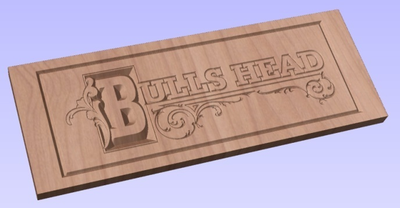
Preview Toolpaths
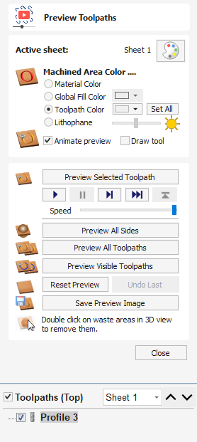
Calculated toolpaths can be previewed to see exactly what they will produce when cut into the material. The 3D preview mode also allows the job to be viewed in different material types with the option to paint the machined regions with a Fill Color.
Active Sheet
The active sheet label shows the sheet that is currently active. Each sheet can be given different material settings. The active sheet can be toggled by clicking within the 2D view, or using the dropdown menu in the toolpaths tree.
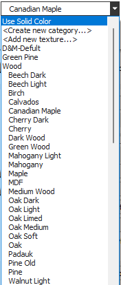
Material Selection
Clicking the color palette icon will pop up the Material Appearance dialog, allowing you to edit the appearance of the 3D shaded image for visualization purposes. The pull-down list offers a range of material types to shade the 3D model.
Use Solid Color
If this is selected the color for the material can be selected from the color picker below the list.
Use Material
The user can choose from the list of pre-defined material effects by clicking on appropriate position on the list. These include many wood grains, metal effects, stone and plastic.
Adding Custom Materials
Additional materials can be added to the library using the list itself. You can add a category (folder) which groups your textures using <Create new category...>. You can also add extra textures under any category using <Add new texture...>.
Alternatively, you can copy an image file (JPG, BMP or TIF) of the material or image you wish to render the job with into the Textures folder within the 'Application Data Folder'. You can open the Application Data Folder from within the program using the File ► Open Application Data Folder menu command.
Shading textures can be obtained from sources such as the internet, clipart libraries or simply create your own from a digital or scanned photographs. For good quality results the image needs to be approximately 1000 pixels x 1000 pixels. The texture image is simply scaled proportionally in X and Y to fit the longest side of the job.
Machined Area Color
Material Color
With this setting, the areas of your preview will simply be colored using the material defined above. Effectively this switches off independent material settings for your machined areas.
Global Fill Color
Paints all the machined regions with the selected color. Selecting the associated pull-down list opens the default color selection form. Click on one of the preset colors, or click to create a completely custom color.
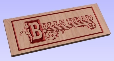
Toolpath Color
If this option is selected, each toolpath can have a different color assigned. If the 'No Fill' option is selected from the color picker form, the current toolpath will be shown in the material color.
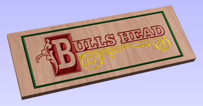
Choose the color you want for the fill of that toolpath and it will be applied to the areas that the toolpath has carved when they are previewed. Once you assign an individual color a small square of that color will be displayed next to the name in the toolpath list. This can be seen top left of each tool icon:
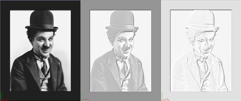
Lithophane
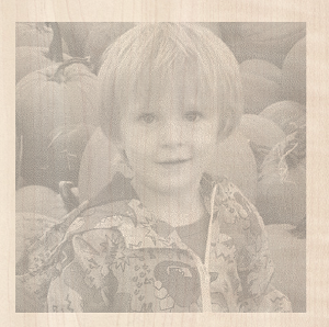
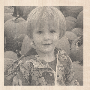
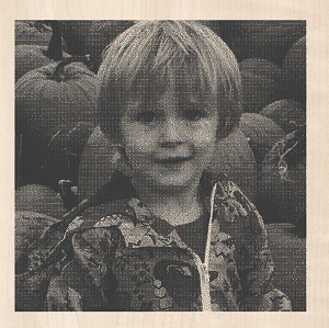
Lithophane mode allows the preview to be shaded to give the effect of a semi-transparent material which is being lit from behind. The thinnest areas of material will appear brightest and then the brightness will be reduced to be lowest at the full material thickness.
Lithophane mode will work with whatever material or solid color is selected. The brightness of the material will vary between white at 0 material thickness and the selected color at full material thickness.
How a lithophane appears can vary depending on many factors including ambient lighting in the room, how strong the light behind the lithophane is and the properties of the material being used. The slider bar next to the lithophane option allows you to adjust the slider to account for these and to pick a value that looks right to you.
The below image shows the effect of changing the brightness slider. A white material has been chosen, as the slider increases from the left to the right the effect changes from being very high contrast to a much lighter appeance like you might see if no backlighting had been applied.
Animation Settings
Animate preview
This option will show the material being removed by the cutter as the preview is drawn.
Draw tool
This option will show a wireframe animation of the tool (to scale) cutting the job.
Toolpath Preview Tools
Preview Toolpath
This option animates the selected toolpath cutting into the material
Preview Control Simulation
The preview controls provide full video-like playback control of your toolpath. You can use this mode to analyze the tool moves in detail, step-by-step. To begin using Preview Control, click on either the Run, Single Step or Run to Retract buttons


Preview All Sides
This option animates all calculated toolpaths cutting into the material on both sides if working in a two sided environment without being in the 'Multi Sided View' mode (This option will be grayed out if working in a single sided setup)
Preview All Toolpaths
This option animates all calculated toolpaths cutting into the material
Preview Visible Toolpaths
Previews all the visible toolpaths
Reset Preview
Resets the material back to a solid block
Save Preview Image
Saves an image of the 3D window as a BMP, PNG, JPG or GIF file
Turn and Spin
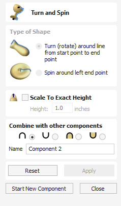
The Turn and Spin tool allows you to create a 3D component by turning or spinning a cross section (an open vector)
Watch this video to see this in action:
Turn
Turn takes a profile and turns (rotates) it around line from start point to end point to create a rounded symmetrical shape. To turn a shape select the vector cross section you want to turn and use the Turn (Rotate) option, this cross section should represent the silhouette of the shape you wish to create. You can click to create your 3D turned shape.
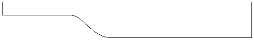
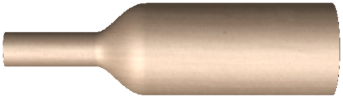
The profile to be turned can run beneath the line between the two end points
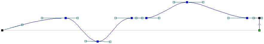
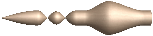
Spin
Spin takes a profile and spins it around the left end point of the cross section to create a circular component based on the profile shape of your cross section. To spin a shape select the vector cross section you want to spin around the left end point and click to create your 3D spun shape.
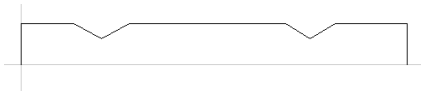
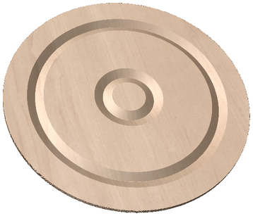
Note
The Spin Tool will always Spin around the left end point, which may require you to move your vector to the right side of your job to accommodate the vector being spun to create the spun shape.
Scale to Exact Height
Checking ✓ this option scales the shape calculated so its maximum height is the value entered in the Height area of the form.
Common Modeling Options
All of the main modeling tools in the software use a common set of commands to assign a name and combine mode to the component being created along with options to apply the settings in the form, reset the shape, start creating a new component and close to exit the function.
Combine with other components...
This section includes options to allow you to name your Component and control the way it will be combined with other objects in the Component Tree.
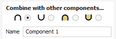
Reset
Clicking the button will remove the current shape, doing this before you Close the form will ensure that a component is not created from the current selection. Clicking this does retain the current set of selected vectors or Components.
Apply
Clicking the button will create a shape based on the settings you have chosen. You can continue making edits to the component by choosing different parameters within the form and hitting Apply to update it.
Start New Component
Clicking the button will save the state of the component that has been created, deselect all components/vectors and start the creation process again on a new component. The values and options within the form will be retained in this case until you Close it.
Close
Clicking the button will close the form returning to the Modeling Tab icons and the updated Component Tree, reflecting any changes that you have made. If you wanted to remove the shape you just created then you can hit the Undo icon or use the keyboard shortcut to undo, CTRL+Z.
Nest Parts
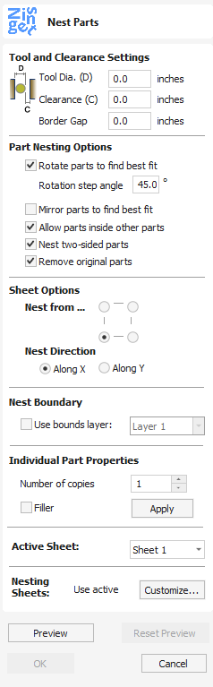
The Nesting tool will automatically fit vector shapes within the user defined area in the most efficient way it can calculate (based on the user defined parameters). By default the area the vectors will be fitted is the current Job Size but it is also possible to select a vector as the nesting area. This is a powerful way to optimize material usage and increase toolpath efficiency when laying out and cutting a number of shapes.
Watch this video to see this in action:
Object Selection
The Nesting tool allows you to select closed vectors, text, components and open vectors that are contained within closed ones.
Once selected the objects will form parts, with part outer boundary highlighted with a thicker line.
The basis for forming parts is overlapping. If selected object contains another or overlaps with it they will be considered the same part.
Tool and Clearance Settings
The settings in this section of the form will determine the spacing which will be left between each of the nested vectors and also control how close they are to the edge of your nesting area.
Tool Dia. (D)
Enter the diameter of the tool that you will be using to Profile (cut-out) the vectors you are nesting. This is the minimum distance that will be left between shapes once they are nested.
Clearance (C)
The Clearance value will be combined with the specified Tool Diameter to create the final minimum spacing between the nested shapes. For example a Clearance of 0.05 inches combined with a Tool Diameter of 0.25 inches would create a minimum spacing gap of 0.3 inches (0.05 + 0.25 = 0.3).
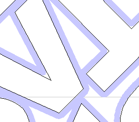
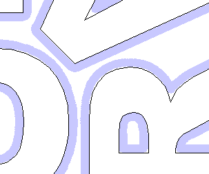
Border Gap
The Border Gap value is applied to the edge of the area which is being used to nest the vectors into. It will be added to the Clearance value around the edge of this shape to create the minimum distance that parts will be nested in respect to the nesting boundary.

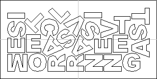
Part Nesting Options
The options in this area of the form will all directly affect how many parts or how efficiently it is possible for the software to fit shapes into the defined nesting area.
Rotate Parts to find best fit
Checking ✓ this option will allow the software to rotate the selected vectors in order to try and better fit them. The increments of rotation the software will use is based on the Rotation step angle.

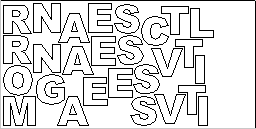
Mirror parts to find best fit
Checking ✓ this option will allow the nesting to mirror (flip) the vectors in order to try and more efficiently nest the selected shapes. This should only be checked ✓ if the direction the parts are cut in is not important.
Allow parts inside other parts
Checking ✓ this option will allow the software to nest within the internal areas of shapes that have gaps in the middle.
When this option is active, the internal areas that will be considered in nesting will be highlighted.


Nest two-sided parts
This option is only available for double-sided projects and allows nesting on both sides simultaneously. When this option is active, any visible objects on the other side will be included, if they intersect with objects selected on active side.
When using this mode it is recommended to perform selection on the side that contains cut-out contours.
When part is selected, the included vectors on the other side will be highlighted as can be seen below.
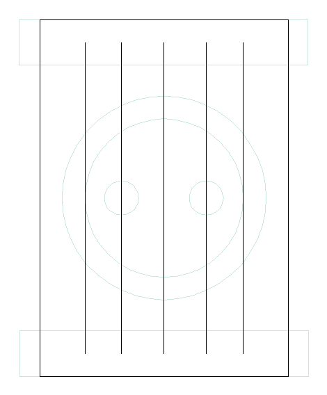
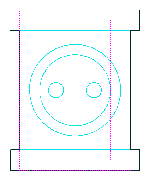
Remove original parts
If this option is checked the original parts are removed in the nesting rather than duplicated in the nest.
Filler Part
Select the vector you wish to use as the Filler Part, tick the "Filler" Tick box and click Apply to set this. The Filler Part Vector will be marked with a Green asterisk (*)
When the Nesting preview is applied, any area not filled by other nesting parts will be filled with as many Filler parts as can be made to fit in the remaining Sheet space.
Sheet Options
Nest From
This area of the form is used to define which corner the nesting will start in. There are four options which can be selected from the options in the form.
Nest Direction
The options in this area of the form are used to select how the parts will progress as they are positioned within the sheet. The best way to think of this (for the purposes of this section) is that they 'pour' out of the selected corner filling the sheet in one axis then advancing along the other defined axis (X or Y) .
Individual Part Properties
If you want more than one incidence of a particular item then select it from the 2D view. In the box where it says Number of Copies enter as many copies as you want and hit and the selected vectors will be marked with a green number indicating how many copies of that item will be made when they are nested. Different shapes or groups of shapes can be assigned different numbers of copies. To stop an item being copied multiple times just set the Number of Copies back to 1 and click .
Nest boundary
A nesting boundary can be specified by choosing a layer whose vectors will represent the nesting boundary. Multiple vectors can be used, allowing holes and areas to be excluded from the nesting to be represented. The nesting process will try to place the nested objects inside the vectors of the boundary layer.
Active Sheet
This option lets you choose which Sheet of vectors is currently active, either for editing or applying toolpaths onto.
Nesting Sheets
For more complicated nesting requirements it is possible to define how the nested parts are placed on to existing sheets and how new copies of existing sheets might be created to accomodate more parts. To edit the default setting click on the Customize button.
The Custom Sheet Selection form show the list of sheets we have to nest on to.
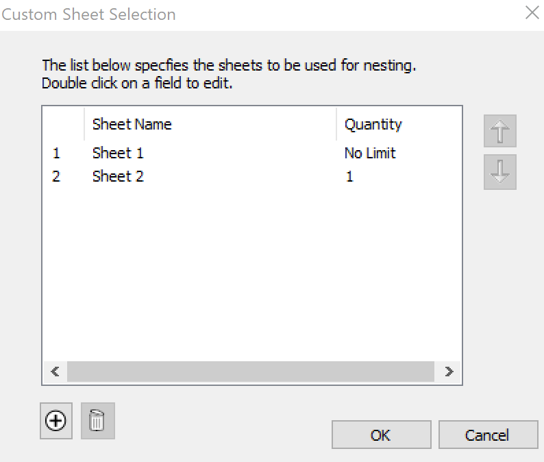
Slice Model
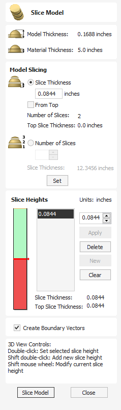
The slicing feature allows the user to divide the Composite Model into Z-Slices each of which will become a Component. This is for customers who need to cut a part which exceeds the Z depth of their machine gantry, the cutting length of their tools or the thickness of the material they are using. Once the slices have been cut on the CNC then they can be re-assembled to make the finished full depth part.
Watch this video to see this in action:
When this function is executed each slice will become a Component in the Component Tree and can then be moved into position and have toolpaths calculated on it. An example of this is shown in the images below, on the left it shows a scallop shell component that is 3 inches thick, the image below right shows this divided into two separate components, each a 1.5 inch slice of the original.
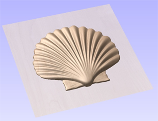
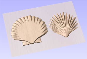
Note
Before using the Slice model command it is important to make sure that you hide any components that you do not wish to include in the operation.
When the icon is clicked the Slice Model form will appear. This can be used to control the number and thickness of slices which will be created. At the top of the form it will display some reference information showing the thickness of the current Composite Model and also the currently defined Material Thickness (for machining).
Model Slicing
The Model Slicing section can be used to set up the initial slices which can later be customized in the Slice Height section.
There are two ways to set up the initial slicing: by setting a standard slice thickness or by setting a fixed number of slices.
Slice Thickness
Checking this option allows you to specify the default slice thickness. You can choose if you want to slice from the top down or bottom up using the From Top checkbox. Each slice is will be the specified thickness, except for the final slice which will be whatever height remains after all the other slices have been taken. If From Top is checked then the final and potenitally thinner slice will be at the bottom. If From Top is uncheched then the final and potentially thinner slice will be at the top.
Number of Slices
Checking ✓ this option will divide the model into a specific number of slices. The slice thickness will be determined by the Composite Model thickness divided by the Number of Slices defined. This may be a good option to use if the specific slice thickness is not important (for instance if it does not relate to material thickness).
Example
If the Composite Model is 3.96 inches thick and you define 3 Slices then the software will create 3 Component slices each 1.32 inches thick.
Create Boundary Vectors
Checking ✓ this option will cause the slicer to create vector boundaries for each slice. These can be useful for defining the subsequent machining regions required to cut each part. The boundary vectors will be placed on the same layer in the 2D View as the component preview for their associated model slice.
Slice Model
Clicking will apply the choices made in the form and create the Components which represent each slice of the Composite Model.
Note
The Component Tree will retain a copy of the original Components in the part as well as the new Slice Components. This may result in a very thick looking model as all the slices will be added to the original shapes. At this point you can delete, undraw or move Components before proceeding with any additional operations.
Close
Clicking will close the Slice Model form without completing the operation.
Slice Heights
The Slice Heights section controls the specific details of each individual slice height. It also allows customization of the number of slices.
There are two parts to the slice height control:
- The height bar which gives a visual indication of the slice heights
- The slice list which lists the slice heights using their z value
The slice height section is for editing the values at which the model is sliced and not the slices themselves.
Controlling Slice Thickness
A specific slice height can be controlled by selecting it from the slice list, updating the value and clicking
Updating the height of a specific slice might potentially adjust the thickness of the surrounding slices
Add New Slices
Additional slices can be added by either:
- Entering a specifc z height for the slice and selecting apply; or
- Double clicking on the height bar at a particular location
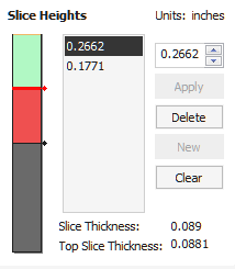
Removing Slices
To remove a slice height select it from the list and press the Delete button. Deleting a slice height will merge the surrounding slices into one slice.
3D View
When the slicing tool is open then the 3D view gives a visualisation of the results of the slicing. If a slice height is selected then:
- Red areas show which are included in this slice
- Green areas indicate that the component is above the slice height and so these will be sliced flat.
- The slice will occur between the Red and the green areas.
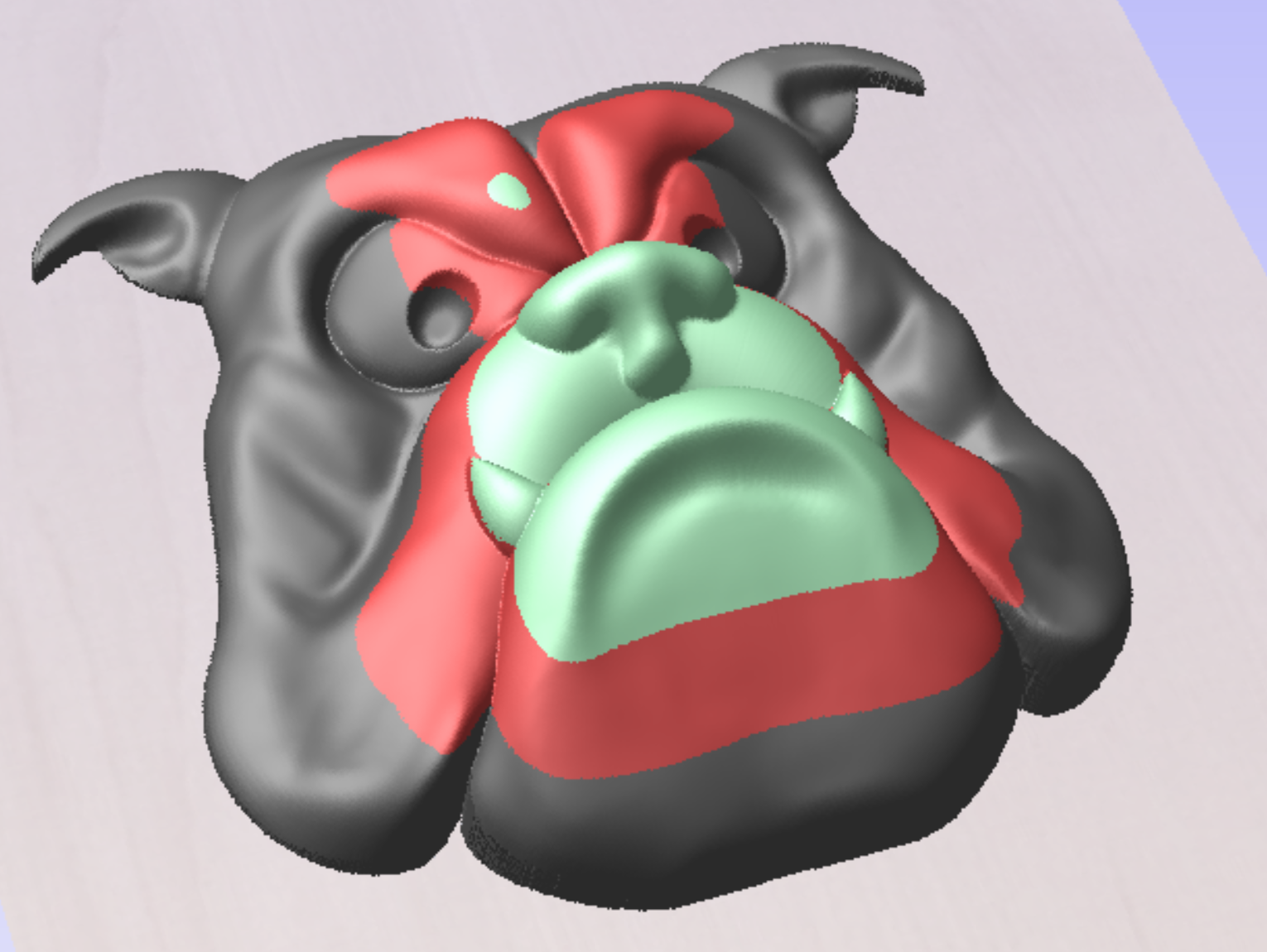
You can also manuipulate the slices within the 3D View
- Double clicking on the model will change the value of the active slice height to be equal to the clicked height.
- Shift + Double Click will insert a new slice height at the clicked height.
- Shift + Mousewheel up/down will raise/lower the actice slice height by a small amount allowing you to tweak the thickness to remove thin slices.
Trace Bitmap
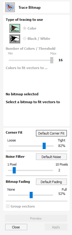
This tool automatically traces or fits vectors to image files so they can be machined. Use the Import Bitmap tool and select the image in the 2D view, then open Fit Vectors to Bitmap.
After importing an image the Tracing option allows vector boundaries to be created automatically around colored or black and white regions in the image.
Watch this video to see this in action:
Tracing a Selected Area of the Bitmap
You can define an area within the bitmap, such that only that part of the bitmap will be traced. This can be done by selecting the bitmap (if this hasn't been done already), and then clicking and dragging the mouse over the area you want, to define a rectangular region on the bitmap. This will be highlighted with a dashed black rectangle.
Clicking on the Bitmap again will remove a selected area if one has been specified, in which case, the entire bitmap will have vectors fitted to it.
Tracing Black and White Images
When working with Black and White images the slider can be used to change the Threshold and merge the levels of gray between all white (min), and all black (max).
When the image being displayed in the 2D view looks correct then clicking the button automatically creates vector boundaries either around the selected Trace Color or the grayscale.
Tracing Color Images
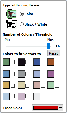
Color images are automatically reduced to 16 colors and the slider allows the visible number of colors to be set as required. Colors are merged with the closest match.
Colors can be temporarily linked together by clicking the check boxes next to each of the colors displayed. This changes the color displayed in the 2D view to the selected Trace Color. This is very useful for merging similar color's together to allow complete regions to be traced.
If a new Trace Color is selected the linked colors are displayed using this color in the 2D view.
The Reset button unlinks all the checked ✓ colors and the image displayed in the 2D view reverts back to the original 16 color image.
2D View
You can select the colours directly from the image in the 2D View.
Tracing a Selected Area of the Bitmap
You can define an area within the bitmap, such that only that part of the bitmap will be traced. This can be done by selecting the bitmap (if this hasn't been done already), and then clicking and dragging the mouse over the area you want, to define a rectangular region on the bitmap. This will be highlighted with a dashed black rectangle.
Clicking on the Bitmap again will remove a selected area if one has been specified, in which case, the entire bitmap will have vectors fitted to it.
Fitting-Options
The options available on this form control how closely the vectors fit / follow the selected color boundaries and these can be modified to obtain improved results.
Corner Fit
The Corner Fit control determines how accurately the vectors are fitted to the corner edges in an image.
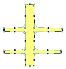
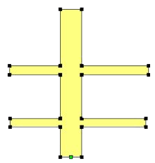
Noise Filter
The Noise Filter slider controls the minimum size of pixels that are traced / vectorized, preventing small unwanted vectors or noise being created.
Bitmap Fading
Preview
This will preview the result of the tracing of the bitmap. If you are not happy with the result provided, you can alter the settings and click on the button again to get an updated result.
Apply
When you are happy with the result of the preview you can click on the button to keep it.
How to Get Started
The first stage in any project is to create a new blank part or import some existing data to work with. At this stage a number of parameters need to be defined relating to the size of the part and its position relative to the datum location on the CNC machine. Later, once the part has been defined and you have started working, you may want to change the size of the material, import additional data and generally manage the project operation. In this section of the manual the initial creation of a part will be covered along with all the icons which appear under the File Operations section of the Drawing Tab.
When you first start the program you will see the Startup Task options on the left hand tab and also a list of your 4 most recently opened Aspire parts (this is a rolling list that will be populated each time you run the software and may initially be empty).
Startup Tasks and Recently Opened Files
When you first start the program you will see the Startup Task options on the left hand tab and also a list of your most recently opened Aspire parts.
In the Startup Tasks section you will have the option to Create a new file, New file from template or Open an existing file.
Creating a new file allows you to specify a size and location for a blank work area, set your material thickness and also set the model quality and even the shading color/material. The process to do this will be covered in the next section (Job Setup Form Options).
New file from template will allow you to start a project using a pre-created template file from your computer. The CRVT3D or CRVT template files will have the necessary information for material size etc. already embedded in it. It may also contain vectors and toolpaths that have been created for this template file. Template file are created for settings you use regularly so you do not need to create them each time.
Open an Existing File, will allow you to open a pre-created file from your computer. This may be a file you previously created (*.crv3d or .crv). Alternatively, it might be a 2D vector layout from another CAD system (.dxf, *.eps, *.ai and *.pdf). A CRV3D or CRV file will have the necessary information for material size etc. already embedded in it. The 2D formats will import the data at the size and position it was created but will require you to go through the Job Setup form to verify/edit all the parameters for the part.
Video Tutorials
The Tutorial Video Browser will open your default web browser (typically Mircosoft Edge, Chrome or Firefox - depending on your Windows setup and personal preference). The web browser offers a number of tutorial videos and associated files, presented either by project or feature category to help you to learn about the software. You will initially need internet access to watch or download the videos or files, but, once downloaded, the materials can be used offline.
We recommend you start with our dedicated Getting Started Videos that cover all typical beginner projects. Watch the first one here:
Online Resources
This section includes direct links to useful websites and web resources like the Vectric website, V&Co portal and forum. These links will also open in your default web browser and you will need internet access to use them.
Social Media
This section includes direct links to the Vectric social media accounts - here you can find the latest news about the software, free projects, Tips and Tricks and events. These links will also open in your default web browser and you will need internet access to use them.
Clipart and Projects
This section includes a direct link to the Design and Make website where you can purchase and download additional clipart. This link will also open in your default web browser and you will need internet access to use them.
Interactive Vector Trim
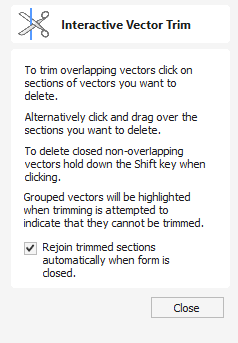
The interactive trimming tool allows the user to just click on sections of vectors they want to delete.
Watch this video to see this in action:
The program finds the closest intersections either side of the clicked portion of the vector and removes the piece of the vector between the intersections. Optionally, when the form for this command is closed, the program can rejoin all the remaining trimmed pieces automatically.
Without using this tool, to remove an overlapping section of a vector, the user would need to insert extra nodes into both vectors, manually delete the intermediate sections and then manually join the resulting pieces. These operations can be performed with a single click using this tool.
When the tool is selected the cursor changes into a 'closed' scissor shape. When the cursor is moved over a vector suitable for trimming the scissors 'open' to show you can click and trim.
If there are lots of vectors to trim then the left-click mouse button can be held down and then when the cursor is dragged and hovers over a vector then it will also trim the vectors. This can be much quicker than individually clicking spans.
Note
If you try to trim a group then the group will flash pink. This indicates that it cannot be trimmed unless it first has to be ungrouped
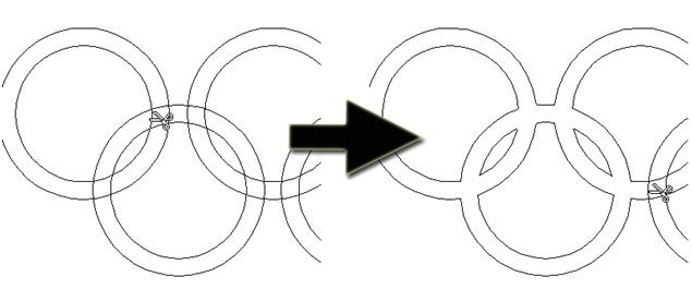
Rejoin Trimmed Sections
Allows the user to select whether the program will automatically try to rejoin trimmed vectors when the form is closed. For most simple cases like that shown above with the overlapping rings, this option can be left checked ✓. If you have an example where for instance many trimmed lines meet at the same point, you may want to uncheck this option and rejoin the vectors manually.
Job Setup - Single Sided
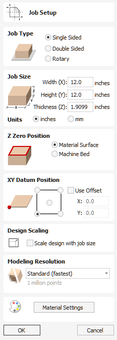
The Job Setup form is displayed whenever a new job is being created, or when the size and position of an existing job is edited.
The size forms may be limited
In most cases a new job represents the size of the material the job will be machined into or at least an area of a larger piece of material which will contain the part which is going to be cut. Clicking OK creates a new empty job, which is drawn as a grey rectangle in the 2D View. Dotted horizontal and vertical Grey lines are drawn in the 2D design window to show where the X0 and Y0 point is positioned.
Job Type
Single Sided job type should be used when design only requires the material to be cut from one side. This is the simplest type of job to design and machine.
Double Sided Job type is useful when it is desired to cut both sides of your material. Aspire allows you to visualise and manage the creation and cutting process of both sides of your design within a single project file.
Rotary job type enables the use of a rotary axis (also called a 4th axis or indexer).Aspire will provide alternative visualisation, simulation and tools appropriate for rotary designs.
Job Size
This section of the form defines the dimensions of the material block you will be using for your project in terms of width (along the X axis), height (along the Y axis) and thickness (along the Z axis).
It also allows you to select which units of measurement you prefer to design in - either inches (Imperial/English) or millimeters (Metric).
Z-Zero Position
Indicates whether the tip of the tool is set off the surface of the material (as shown in the diagram) or off the bed / table of the machine for Z = 0.0.
XY Datum Position
This datum can be set at any corner, or the middle of the job. This represents the location, relative to your design, that will match the machine tool when it is positioned at X0, Y0. While this form is open, a red square is drawn in the 2d view to highlight the datum's position.
Use Offset
This option allows the datum position to be set to a value other than X0, Y0.
Design Scaling
When editing the Job Size parameters of an existing job, this option determines whether any drawings you have already created will be scaled proportionally to match the new job dimensions. If you wish to preserve the existing size of your drawings, even after the job size has changed, leave this option unchecked. With this option checked, your drawings will be re-sized to remain in the same proportion and relative position within your new material extents when you click
Modeling Resolution
This sets the resolution/quality for the 3D model. When working with 3D models a lot of calculation and memory may be required for certain operations. Setting the Resolution allows you to choose the best balance of quality and speed for the part you are working on. The better the resolution quality chosen, the slower the computer will perform.
As this is completely dependent on the particular part you are working on and your computer hardware performance, it is difficult in a document like this to recommend what the setting should be. Generally speaking, the Standard (fastest) setting will be acceptable for the majority of parts that Aspire users make. If the part you are making is going to be relatively large (over 18 inches) but still has small details, you may want to choose a higher Resolution such as High (3 x slower) and for very large parts (over 48 inches) with small details then the Highest (7 x slower) setting may be appropriate.
The reason that the detail of your part needs to be taken into account is that if you were making a part with one large item in it (e.g. a fish) then the standard resolution would be OK but if it was a part with many detailed items in it (e.g. a school of fish) then the High or Highest setting would be better. As previously stated these are extremely general guidelines as on slower/older computers operations with the highest setting may take a long time to calculate.
As the Resolution is applied across your whole work area it is important to set the size of your part to just be big enough to contain the part you plan to carve. It would not be advisable to set your material to be the size of your machine - e.g. 96 x 48 if the part you plan to cut is only 12 x 12 as this would make the resolution in the 12 x 12 area very low.
Appearance
Clicking will pop up a dialog allowing you to set the color or material effect which will be applied to the base 3D model. It is possible to change this at any time and also to apply different colors and materials to different Components using the Component manager. See Preview Toolpaths to learn more about different material settings and adding custom material effects.
11. Advanced - Importing External Models in a Rotary Project
Importing Full-3D models
This section will present the process of importing the Full-3D STL model into rotary project, using a table leg as an example.
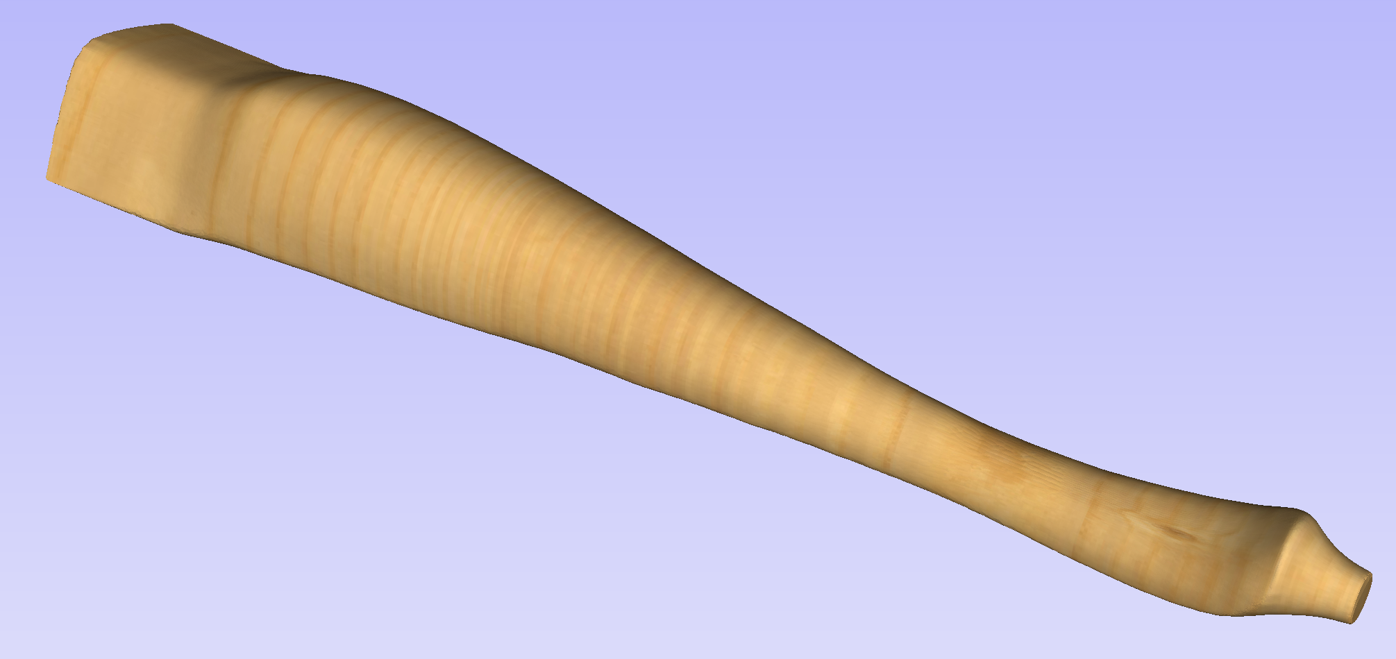
Overview
There are two basic use cases when importing an external model into the rotary job. The first case involves bringing a model designed for this particular job in another software. Thus the dimensions of the imported piece may already be correct and it can be desired to use them for the size of project. The second use case is when importing a stock model that would have to be scaled to fit on particular machine.
Aspire uses following workflow that covers both of those cases:
- Setting-up rotary project
- Choosing file for import
- Orientating the model in material block
- Scaling the model
- Finishing the import
Setting up a rotary project
Create a new job using the Job Setup form. It is important to set the job type as rotary to ensure a proper import tool is used in the next step.
If the dimensions of the project are already known, they could be specified directly.
If it is desired to fit the model to a given machine or stock available, set both the diameter and length to maximum. During import the model will be scaled to those limits.
If it is desired to use the imported model size, any size can be specified at this time. During the model import the project can be automatically resized to match the model dimensions.
In this example it was desired to fit the model into a specific stock size with a Diameter of 4 inches and a Length of 12 inches. XY origin was set to centre.
Importing the file and orientating it
To start the importing process, use Import a Component or 3D Model tool from the Modelling tab
Make sure that the Imported model type is set to Full 3D model .
The first step is to position the imported model within the material. This step is necessary as this information is not present in the imported file. When the model was opened, the import tool chose the initial orientation, as can be seen below.
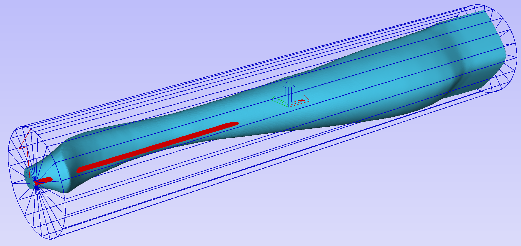
To help with orientating the model, the software displays a blue bounding cylinder. This cylinder has the rotation axis aligned with that defined for the material block and thus can be used as a reference. Its size is just big enough to contain the imported model at the current orientation. When the model orientation is changed, this blue cylinder will shrink or grow so it always contains the model. At this stage its exact dimensions are not important, as we are only interested in positioning the model correctly.
The software also highlights the rotation axis in red. This is particularly important when importing bended models. It is currently not possible to represent areas of model that are entirely below or above the rotation axis. This is the case in the example shown here. If the model was imported as is, the distortion would be created as can be seen below. Therefore it is important to position the model in a way such that the rotation axis is contained within the model.
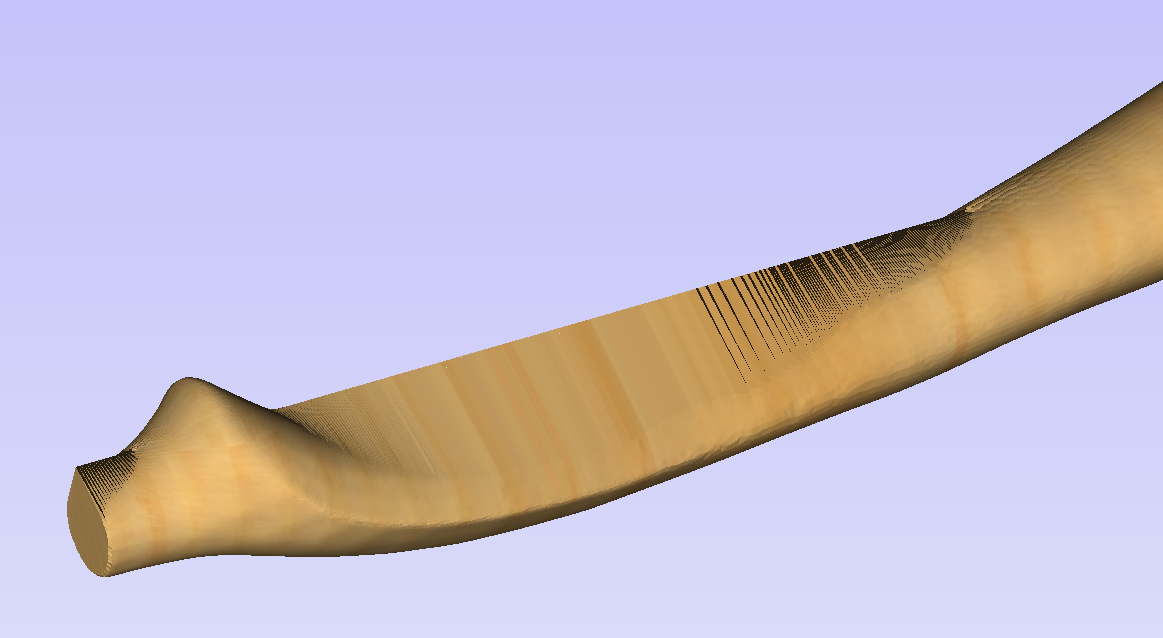
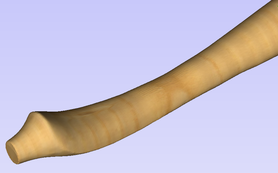
The last guiding element displayed by the software is the red half arrow on the side of the cylinder. This arrow is indicating the position that corresponds to the center of the wrapped dimension in the 2D view. In this example the model is orientated in such a way, that front of the leg would be placed on side of the 2D view, rather than centre. Thus it is better to rotate model so this arrow points to the front of the imported model.
The import tool provides a few ways of adjusting the model orientation. The most basic one is the Initial Orientation. This can be used to roughly align the model with the rotation axis. This can also be combined with the Rotation about Z Axis.In this example the tool chose Left with no rotation. In order to align the front of the leg with the red arrow, one could use the Front and -90 as the Rotation about Z Axis.
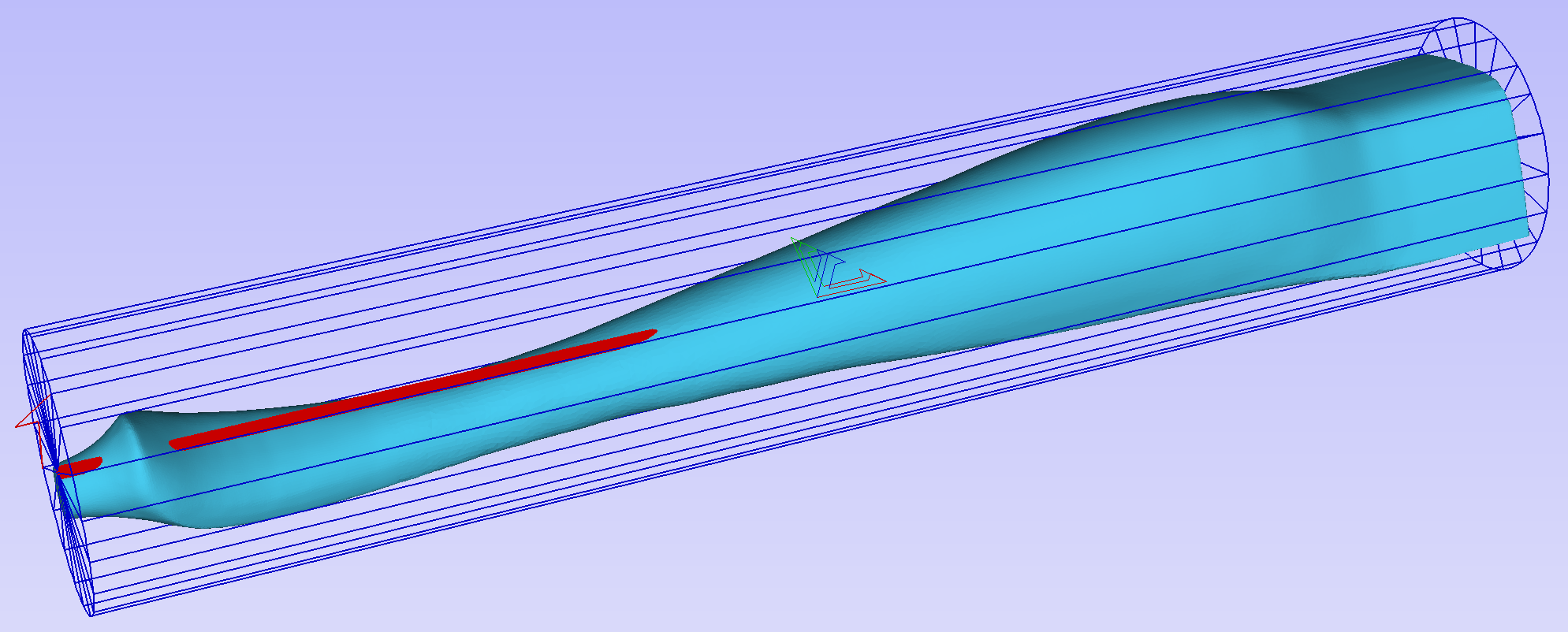
Once the initial orientation is decided, further adjustments can be made using the Interactive Rotation. The default option - XYZ View - disables the interactive rotation. That means that the 3D view can be twiddled with a mouse. Selecting other options enables the rotation around the specified axis.
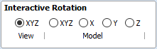
In this example, instead of changing the initial orientation to align the front of the leg with the red arrow, one could select X Model option and rotate the piece manually. When selecting single axis rotation, the 3D view will be adjusted to show that axis pointing towards the screen. If any mistake is made, it is possible to undo rotation using Ctrl+ Z
Notice that whenever the part is rotated, it is always centered in the cylinder. In this example it is not desired, since we need the rotation axis to be contained within the model. In order to move the model in relation to the rotation axis, one can use the Rotation Axis Movement
Similarly to the previously described tool, when Rotation Axis Movement is set to Off, the 3D view can be panned
Correctly positioning the model for importing may require a combination of the Rotation Axis Movement and the Interactive Rotation to achieve desired results with models that bend. It is important to make sure that rotation axis is hidden in order to avoid distortion. However it is also desirable to have the rotation axis being in the center of each segment of the piece to ensure tool has angle close to the optimal during machining. Usually it is also useful to rotate the model in view around the axis after the adjustment, as this allows us to inspect the model from each side without the need to disable the Interactive Rotation before changing the viewing angle.
It is important to understand that Aspire does not support 4-axis machining. That means that while the machined piece can be rotated and tool moves along the rotation axis and in the Z direction, it is not possible to move the tool in the wrapped dimension and thus the tool is always above the rotation axis and cannot be moved to the side.
This limitation is shown below. The first picture presents correct machining of the point. If the tool moves to another location though, the angle will be incorrect and even worse, the tool side will be touching the stock.
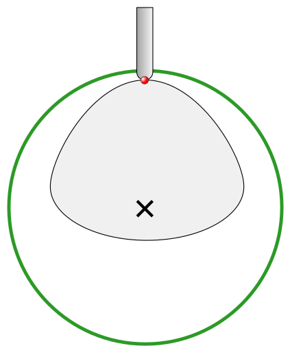
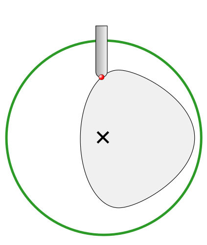
Scaling imported model
Once model has been positioned as desired, its size can be taken into account.
By default the tool will assume that imported model is using the same units as the project. If that is not the case, model units can be switched. In this example project was set-up in inches, while imported model was designed in mm. After switching model becomes considerably smaller and a red cylinder, representing current material block is shown, as can be seen below.
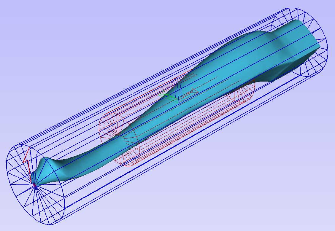
At this point it is possible to specify the model size, in terms of diameter and length. This can be done manually by typing desired dimensions, or by fitting to material. If Lock ratio option is selected, the ratio between diameter and length is kept. One can also tick Resize material block option. If it is selected, the material block will be scaled to match current size of the model, after OK is clicked.
If it is desired to use model size as material block size, one can just make sure units are correct, then tick Resize material block option and press OK.
If it is desired for the model to fit material, one could click Scale model to fit material and tick Resize material block.
In this example model was fitted to material. Since in this case length of the piece is limiting factor and lock ratio is maintained, this results in model having considerably smaller diameter than material block. Hence Resize material block option was ticked.
Finishing import
After pressing OK the model will be imported as a component. It is possible to modify it as any other component or add pieces of decorative clipart onto its surface if desired.
It is important to keep in mind the distortion caused by the wrapping process. That means that wrapped toolpaths will match flat toolpaths only at the surface of the blank. The closer to the rotation axis (i.e. deeper) the toolpath is, the more it will be 'compressed'. This fact have a profound implication for 3D toolpaths. Consider the example shown below.
As can be seen if there is substantial difference in diameter in different parts of model, generating one 3D toolpath for whole model will result in wrapped toolpath being overly compressed. Thus it is usually better to create boundaries of regions with significantly different diameter and generate separate toolpaths using correct settings for each diameter.
Importing Flat Models
This section will present a process of importing Flat STL model into rotary project. Flat models are similar to decorative clipart pieces provided with Aspire and are supposed to be placed on the surface of modelled shape.
To start the importing process, use Import a Component or 3D Model tool from the Modelling tab
Make sure that Imported model type is set to Flat model
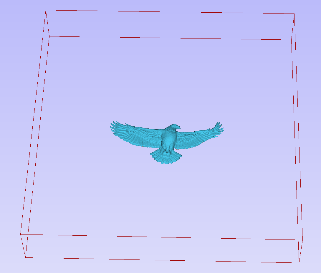
Again the first step is to select proper orientation of model. The tool will chose initial orientation and display model in the red material box. This box corresponds to the 'unwrapped' material block and its thickness is equal to half of the specified diameter of the blank.
If model is not oriented correctly, that is, does not lie flat on the bottom of the material box, as can be seen above, orientation have to be adjusted. To do that one can change Initial Orientation option and/or Rotation about Z Axis.
If imported model is not aligned with any of the axes, it may be necessary to use Interactive Rotation.The default option - XYZ View - disables interactive rotation. That means that 3D view can be twiddled with a mouse. Selecting other options enables rotation around specified axis.
Each rotation can be undone by pressing Ctrl+ Z.
Once model is properly orientated, units conversion can be performed. By default the tool will assume that imported model is using the same units as the project. If that is not the case, model units can be switched.
There is also model scaling option included. When Lock ratio option is selected, the ratio between X, Y and Z lengths are kept. Note that once model is imported, it will be added to project as a component. Hence correct placement, rotation and sizing can be performed later, after model is imported.
If the project does not contain any models yet, following message will be displayed:
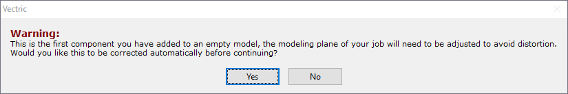
Typically you could simply click Yes.The more detailed explanation about modelling plane adjustment has been provided in Modelling 3D rotary projects
Crash Handling
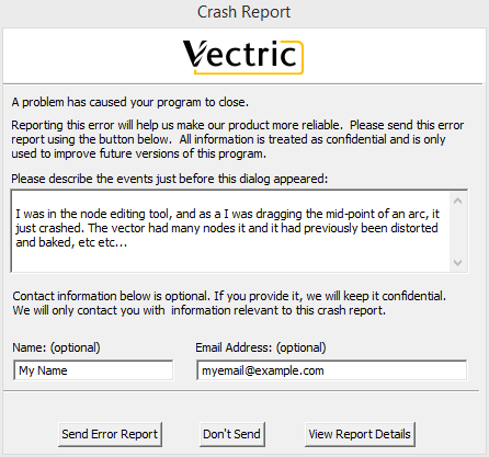
In the unfortunate event of the software crashing,
- We try to save unsaved changes, so that your data isn't lost.
- Provide an easy way for you to report the crash so that we can work on a fix.
Project Saving
If you're working on a job and the software crashes, the first thing it will try to do is to save your project. The project will be saved alongside your original to avoid accidentally corrupting your original file.
Report the crash
A dialog will pop up asking you to upload the crash information which will help us track down the issue. Any information you can think of would be greatly appreciated and will help us fix the issue in a timely manner.
Description
Please try to remember what you were doing at the time, and describe it for us. Please include any information you can think of. Any bit of information can help us track the issue quicker, so we greatly appreciate that.
Information
You can include your name and e-mail to allow us to get back to you with questions in case we need more information. For example, we may need the project that you were working on. This data will not be used for any purpose other than to help us track down the issue.
Internet
You will need to be connected to the internet for this to work. If not, you can still send the generated zipped report to support@vectric.com. The report can be found in the Application Program Data (Accessible through the menu File ⇛ Open application data folder.... If you try to send the report and it fails, you will get a message of where that path is and possible methods to get that report to us.
The crash reporting is powered by BugSplat (a third-party) company which provides us with the tools that help us analyse them.
Edit Picture
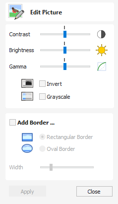
The Edit Picture form allows you to add a border to, and edit the properties of a selected bitmap.
Watch this video to see this in action:
Contrast
This slider adjusts the contrast.
A higher contrast emphasises the differences between the light and dark parts of the image.
A lower contrast will reduce that difference and make the image more neutral and average.
Brightness
This slider adjusts the brightness of the image.
Gamma
This slider adjusts the gamma correction applied to the image. This can make an image look lighter or darker whilst maintaining detail.
Invert
Inverts the colors in the image. White becomes black and black becomes white
Grayscale
Makes the image black and white.
Add Border


Fades the edges of the image based on the border type and the width of the fading.
Edit Sheet - Rotary
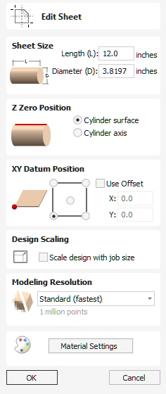
The Job Setup form is displayed whenever a new job is being created, or when the size and position of an existing job is edited.
In most cases a new job represents the size of the material the job will be machined into or at least an area of a larger piece of material which will contain the part which is going to be cut. Clicking OK creates a new empty job, which is drawn as a gray rectangle in the 2D View. Dotted horizontal and vertical Grey lines are drawn in the 2D design window to show where the X0 and Y0 point is positioned.
Job Size
Length
Length of the material
Diameter
Diameter of the material
Units
Whether the job units are measured in mm or inches
Z Zero Position
Indicates whether the tip of the tool is set off the rotation axis (as shown in the diagram) or off the surface of material for Z = 0.0. For the best accuracy using Cylinder Axis option is recommended
XY Datum Position
This datum can be set at any corner, or the middle of the job. This represents the location, relative to your design, that will match the machine tool when it is positioned at X0, Y0. While this form is open, a red square is drawn in the 2d view to highlight the datum's position.
Use Offset
This option allows the datum position to be set to a value other than X0, Y0.
Orientation
This option selects along which axis the material block will rotate.
- Selecting Along X Axis means that X coordinates represent movement along the cylinder, whereas Y coordinates represent the angle around the cylinder.
- Selecting Along Y Axis means that Y coordinates represent movement along the cylinder, whereas X coordinates represent the angle around the cylinder.
Flip Design
When this option is enabled, the design will be flipped when the orientation is changed
Design Scaling
When editing the Job Size parameters of an existing job, this option determines whether any drawings you have already created will be scaled proportionally to match the new job dimensions. If you wish to preserve the existing size of your drawings, even after the job size has changed, leave this option unchecked. With this option checked, your drawings will be re-sized to remain in the same proportion and relative position within your new material extents when you click
Modeling Resolution
This sets the resolution/quality for the 3D model. When working with 3D models a lot of calculation and memory may be required for certain operations. Setting the Resolution allows you to choose the best balance of quality and speed for the part you are working on. The better the resolution quality chosen, the slower the computer will perform.
As this is completely dependent on the particular part you are working on and your computer hardware performance, it is difficult in a document like this to recommend what the setting should be. Generally speaking, the Standard (fastest) setting will be acceptable for the majority of parts that Aspire users make. If the part you are making is going to be relatively large (over 18 inches) but still has small details, you may want to choose a higher Resolution such as High (3 x slower) and for very large parts (over 48 inches) with small details then the Highest (7 x slower) setting may be appropriate.
The reason that the detail of your part needs to be taken into account is that if you were making a part with one large item in it (e.g. a fish) then the standard resolution would be OK but if it was a part with many detailed items in it (e.g. a school of fish) then the High or Highest setting would be better. As previously stated these are extremely general guidelines as on slower/older computers operations with the highest setting may take a long time to calculate.
As the Resolution is applied across your whole work area it is important to set the size of your part to just be big enough to contain the part you plan to carve. It would not be advisable to set your material to be the size of your machine - e.g. 96 x 48 if the part you plan to cut is only 12 x 12 as this would make the resolution in the 12 x 12 area very low.
Appearance
Clicking will pop up a dialog allowing you to set the color or material effect which will be applied to the base 3D model. It is possible to change this at any time and also to apply different colors and materials to different Components using the Component manager. See Preview Toolpaths to learn more about different material settings and adding custom material effects.
Draw Star
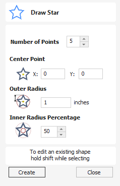
Stars can be created interactively with the cursor and Quick Keys, or by entering the number of points, exact coordinates and outer radius and inner radius percentage using typed input.
Watch this video to see this in action:
Interactive Creation
The quickest and easiest way to create a star is by clicking and dragging the shape to size in the 2D View using the mouse.
- Click and hold the left mouse button to indicate the center point.
- Drag the mouse while holding down the left mouse to required radius.
- Release the left mouse button to complete the shape.
Note
Holding Alt and dragging creates a star from the middle point.
As the cursor is dragged across the screen so the outer radius is dynamically updated. The increments will depend upon your snap radius and the job size.
Quick Keys
Instead of releasing the left mouse button when you have dragged your shape to the required size, you can also type exact values during the dragging process and set properties precisely.
- Left-click and drag out your shape in the 2D View.
- With the left mouse button still pressed, enter a quick key sequence detailed below.
- Release the left mouse button.
Default
By default, entering a single value will be used to set the outer radius of your star. While you are dragging out the star, type Radius Value Enter to create a star with the precisely specified outer radius.
Example
- 2 . 5 Enter - Creates a start with an outer radius of 2.5 all other settings as per the form
Specifying Further Properties
By using specific letter keys after your value, you can also indicate precisely which property it relates to.
Note
When specifying multiple properties with quick keys, it is still important that they are entered in the order indicated in the table below.
- Value D - Creates a start with the outer Diameter (D) specified with all other properties as per the form
- Value I Value R - Creates a star with the inner radius percentage (I) and the outer radius (R). The inner radius is defined in terms of a percentage of the outer radius or diameter. All other properties are as per the form.
- Value P Value R - Creates a star with the specified number of points (P) and the outer radius (R).
- Value P Value I - Creates a star with the specified number of points (P), inner radius percentage (I) and the outer radius (R).
Examples
- 1 R - Outer radius 1, other properties as per form
- 1 D - Outer diameter 1, other properties as per form
- 6 P 1 R - A 6 pointed star with an outer radius of 1
- 6 P 2 5 I 4 D - A 6 pointer (P) star with an outer diameter (D) of 4 and an inner diameter that is 25% of the outer (i.e. 1).
Exact Size
Stars can also be drawn by entering the Number of Points, Center Point, Outer Radius and Inner Radius Percentage.
- Click to update the star.
Usable In Both Views
This tool can be used in both the 2D and 3D View.
2D View offers a more direct way to view your vectors while 3D Offers more flexability to work with Vectors in 3D Designs and to make use of the Edit Boxes.
Help
Help Contents | Displays an online version of the full reference manual that documents every feature and option available in the software. Note The reference manual is not intended as a User Guide or introductory training resource - please don't forget about the Getting Started guides and the extensive video tutorial library on your install media. |
Keyboard Shorcuts | Displays the Shortcut Keys |
Video Tutorial Browser... | Access the tutorials |
What's New | See a summary of the new features added in major and minor updates. |
Release Notes | See the list of issues fixed and enhancements in patch updates. |
Third Party Licences | Display a list of all the third party software used to help create Aspire. |
Enter License Code | Displays the License Dialog used for entering license or module details. |
View the Vectric Online FAQ... | Displays the Frequently Asked Questions (FAQs) |
View the Vectric User Forum... | Opens the Vectric User Forum in your Web Browser if you have an Internet Connection. Everyone should join the Forum to engage with other users and benefit from each others tricks and tips! |
Visit Vectric Support online... | Opens the Vectric Support Website in your Web Browser if you have an Internet Connection. |
Visit Vectric User Portal... | Opens the Vectric User Portal in your Web Browser if you have an Internet Connection. Download software installation files, activation codes and Clip Art included with the software. |
Post Processor Editing Guide | Opens the page explaining how to create and edit your own post processors. |
Migrate From Older Version | Opens a dialog to enable the settings in the last version of Aspire to be copied to the latest version. 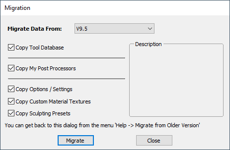 |
Check for Updates | Try this periodically to check (through the Internet) if an update is available for your software. |
Run Kickstarter | Opens a wizard allowing the user to get started. |
About Aspire... | This window displays the version of the software being used, to whom the software is license and the type of license. |
Post-Processor Content
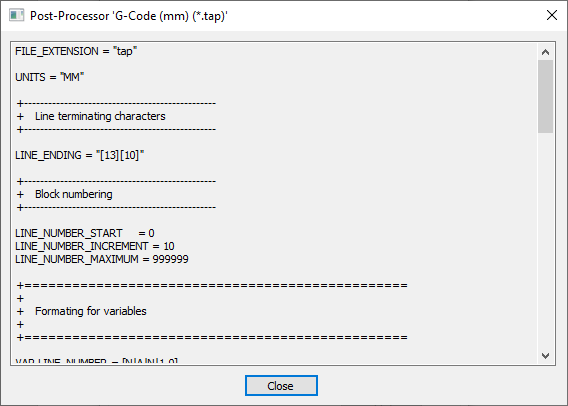
This window allows you to view the contents of the selected post-processor file.
This can be viewed from the Machine Configuration Management dialog and costomized through the Post-Processor Management dialog.
To view, open the Machine Configuration Management dialog, click on the post processor that you wish to view with the Right hand mouse button and select "View" from the right hand click menu.
Please note: The view option is not available for custom post processors that you have placed in your My_PostP folder.
Machine Configuration Post-Processor
In the Machine Configuration Management dialog, you have the ability to define a fixed version of the post-processor for use. Viewing this post-processor through there will be showing you the content of that version you have selected, and not the contents of the latest version. If you want to see the contents of the latest version, then you need to View the post-processor through the Post-Processor Management dialog.
POST_NAME
If you would like to copy the contents of this post-processor and use it, you will need to add a POST_NAME statement at the top of the file. This will be done automatically for you if you choose the 'Customise' option instead.
You can cut and paste content in text form to the clipboard of your computer.
Custom Post-Processor
Within the Post-Processor Management dialog form you can mark a post processor as being a custom one. To do this click on the Edit icon

This will move the selected post processor to your My_PostP folder. You can make edits to this post processor with any text editior.
License Dialog
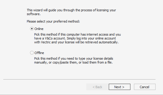
The License Dialog is used to set the details you need to activate the software. This dialog can also be used to activate optional modules. The page that initially appears will give you the option to set your license details either automatically from your V&Co account or manually.
The "Online Method" section below covers the process to follow if Online is selected.
The "Manual Method" section below shows the process to follow if you wish to type in your license details manually or do not have an Internet connection available.
Online Method
This method will allow you to retrieve your details automatically from your V&Co account. To use this select 'Online' and then click on the form. The online section of the form will then be displayed.
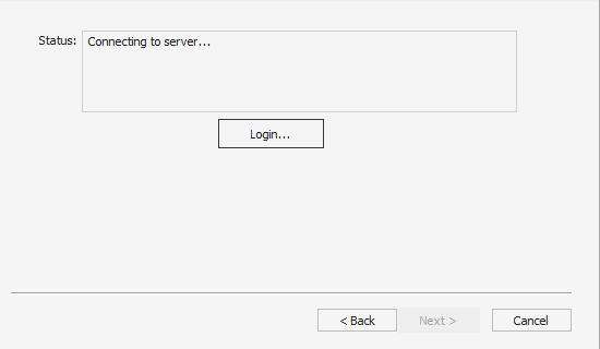
Pressing on this dialog will launch a web browser which will take you to the V&Co login page if authentication is required.
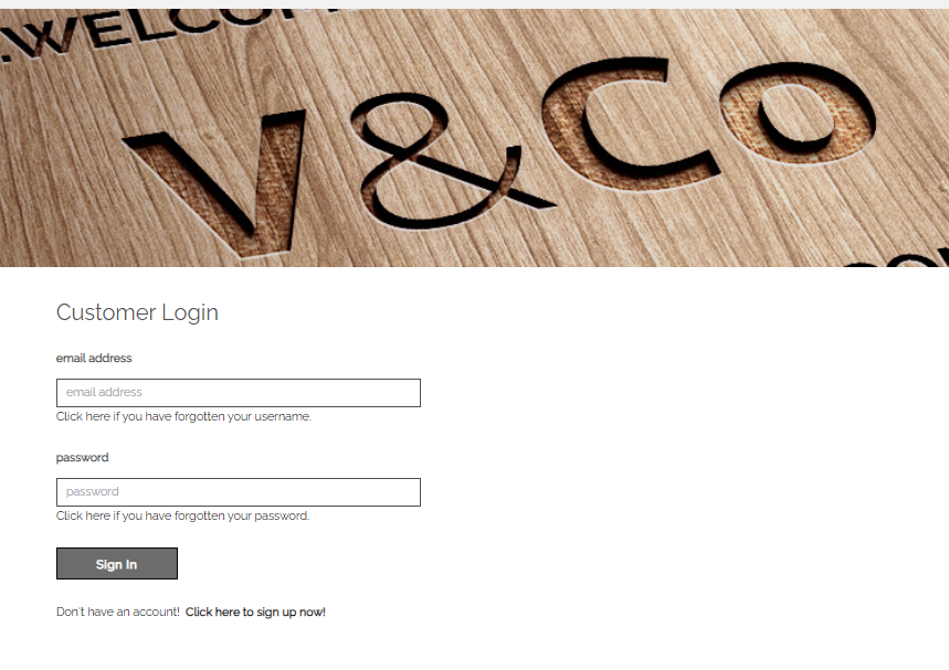
After logging in here with your V&Co account details another page may appear asking for permission for Aspire to access your license details.
This page will only appear if you have not already granted access. If this appears you should select "Allow" to enable Aspire to retrieve your license details automatically.
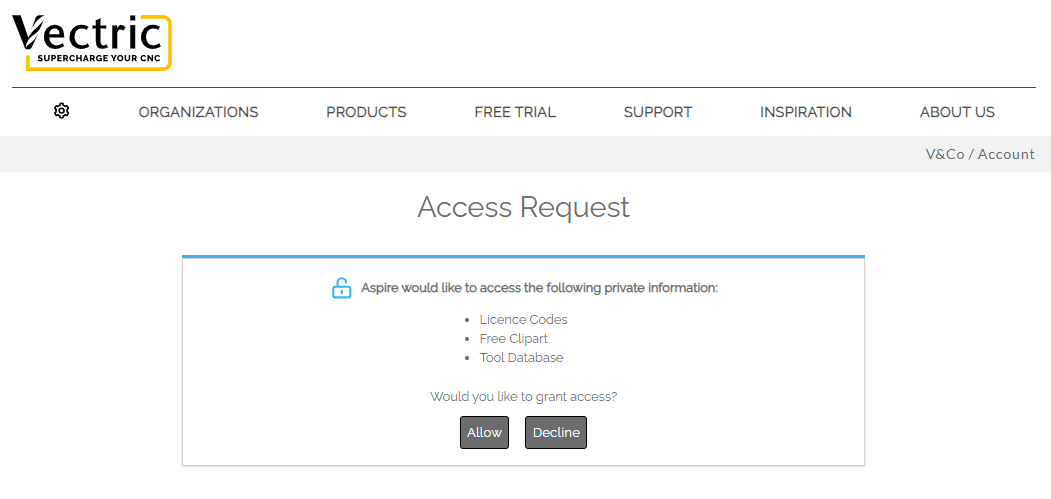
At this point Aspire should be being displayed and the dialog should be automatically populated with any licenses available on your account.
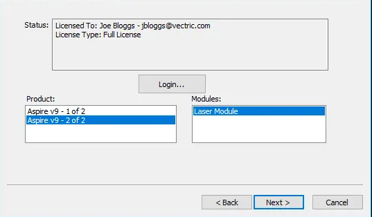
You can select any of the product licenses available and information on the type of license will be displayed in the status area. Once the license and any modules have been selected by clicking on them can be pressed to activate these and proceed to the summary page.
Note
If there is only a single license available on your account the above page is skipped and the summary page (below) will already be displayed.
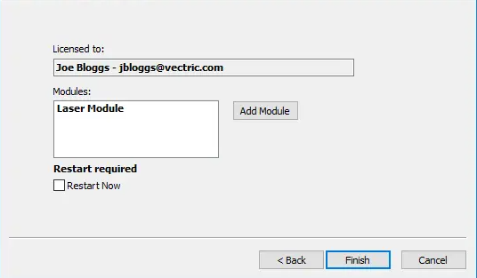
This page displays the selected license and module details. If you are changing current license details or adding a module a restart will be required for these to fully take effect. In this case a check box will appear allowing you to restart automatically. If this is checked then when you press Aspire will automatically be restarted to apply the license changes. If you do not select this option the license changes take effect the next time Aspire is restarted.
Manual Method
The manual method allows entry of license details without requiring an Internet connection.
There are 2 methods for entering a licences,
- Loading from a File
- Typing or Copying the values into the text fields
Load from File
You can choose to download a vlicence file from your V&Co account.
There are 2 ways to use this file
- Double-click the file to open it with the software
- Go through the License Dialog wizard and click to Load the vlicence file.
Multiple Software Installations
If you have a previous version of the software installed, please make sure you use the correct installation of the software to open the vlicence file with.
Manual
License Data
You can get the License Data from your V&Co account and enter it using the Enter License Data option.
Example License Data
---BEGIN VECTRIC LICENCE--- eyJ2ABCDEFGHIJKLMNOPQRSTUVWXYZ0123456789eyJ2ABCDEFGHIJKLMNOPQRSTUVWXYZ012345 6789eyJ2ABCDEFGHIJKLMNOPQRSTUVWXYZ0123456789eyJ2ABCDEFGHIJKLMNOPQRSTUVWXYZ01 23456789eyJ2ABCDEFGHIJKLMNOPQRSTUVWXYZ0123456789eyJ2ABCDEFGHIJKLMNOPQRSTUVWX YZ0123456789eyJ2ABCDEFGHIJKLMNOPQRSTUVWXYZ0123456789eyJ2ABCDEFGHIJKLMNOPQRST UVWXYZ0123456789eyJ2ABCDEFGHIJKLMNOPQRSTUVWXYZ0123456789== ---END VECTRIC LICENCE---
Registered User Name & License Code
If you are not registered but you have received a Register User Name and License Code with your recently purchased machine, then you can enter those using the Enter User Name & License Code option.
Example Registered User Name & License Code
Registered User Name My Machine Test - 00100 License Code ABCDEF-GHIJKL-MNOPQR-STUVWX-YZ0123-456789-ABCDEF-GHIJKL-MNOPQR-STUVWX
Copying the License Code
You can copy the entire code into the first field and will automatically fill the rest of the text fields.
If the product is already licensed then a module code can be entered at this stage instead of the product code. If you wish to manually activate both a product and module code the product code should be added here and there will be an opportunity to add the module code later.
Pressing will set the license and display the summary screen.
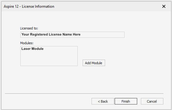
Adding Module
The summary screen shows the current licensed user and has an button to allow additional modules to be added. Pressing this button will display the manual entry form again and allow the module details to be entered.
If the licensed user is changed or a new module is added a restart will be required for these to take full effect. In this case a check box will appear allowing you to restart automatically. If this is checked then when you press the finish button the program will automatically be restarted to apply the license changes. If you do not select this option the license changes take effect the next time the program is restarted.
Create Component from Bitmap
This tool lets you automatically create a 3D Component from a Bitmap.
If no Bitmap is selected in the 2D View, then a File dialog will open allowing you to select an image file from one of the drives on your computer. This method of component creation bypasses the need to convert the image when importing which potentially reduces the number of color shades, so this second method is the best way to directly convert Bitmap files to components in Aspire.
The Component from a Bitmap is automatically scaled and set to Add to other Components by the software so will typically need to be edited using the Component Properties icon to adjust height or Combine Mode and the Transform tools to adjust its size and position.
Watch this video to see this in action:
Converting selected bitmap
If you have a selected Bitmap in the 2D View this will automatically create a new component derived from that Bitmap, the Component will have the same name as the original image.
Converting without bitmap selected
If no Bitmap is selected in the 2D View, then a File dialog will open allowing you to select an image file from one of the drives on your computer. This method of component creation bypasses the need to convert the image when importing which potentially reduces the number of color shades, so this second method is the best way to directly convert Bitmap files to components in Aspire. This is especially important for 16-bit images.
Edit Sheet - Double Sided
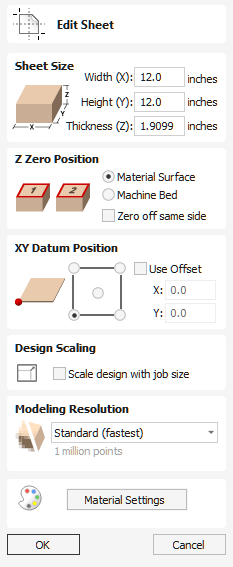
The Job Setup form is displayed whenever a new job is being created, or when the size and position of an existing job is edited.
In most cases a new job represents the size of the material the job will be machined into or at least an area of a larger piece of material which will contain the part which is going to be cut. Clicking OK creates a new empty job, which is drawn as a gray rectangle in the 2D View. Dotted horizontal and vertical Grey lines are drawn in the 2D design window to show where the X0 and Y0 point is positioned.
Job Type
Single Sided job type should be used when design only requires the material to be cut from one side. This is the simplest type of job to design and machine.
Double Sided Job type is useful when it is desired to cut both sides of your material. Aspire allows you to visualise and manage the creation and cutting process of both sides of your design within a single project file.
Rotary job type enables the use of a rotary axis (also called a 4th axis or indexer).Aspire will provide alternative visualisation, simulation and tools appropriate for rotary designs.
Job Size
This section of the form defines the dimensions of the material block you will be using for your project in terms of width (along the X axis), height (along the Y axis) and thickness (along the Z axis).
It also allows you to select which units of measurement you prefer to design in - either inches (Imperial/English) or millimeters (Metric).
Z Zero Position
Indicates whether the tip of the tool is set off the surface of the material (as shown in the diagram) or off the bed / table of the machine for Z = 0.0.
Zero off same side
This option allows Z Zero to reference the same physical location, regardless whether material is flipped or not
XY Datum Position
This datum can be set at any corner, or the middle of the job. This represents the location, relative to your design, that will match the machine tool when it is positioned at X0, Y0. While this form is open, a red square is drawn in the 2d view to highlight the datum's position.
Use Offset
This option allows the datum position to be set to a value other than X0, Y0.
Flip Direction Between Sides
This section gives choice between horizontal and vertical flipping when changing machining side. Aspire uses that information to correctly manage the alignment of the geometry relating to each side.
Design Scaling
When editing the Job Size parameters of an existing job, this option determines whether any drawings you have already created will be scaled proportionally to match the new job dimensions. If you wish to preserve the existing size of your drawings, even after the job size has changed, leave this option unchecked. With this option checked, your drawings will be re-sized to remain in the same proportion and relative position within your new material extents when you click
Modeling Resolution
This sets the resolution/quality for the 3D model. When working with 3D models a lot of calculation and memory may be required for certain operations. Setting the Resolution allows you to choose the best balance of quality and speed for the part you are working on. The better the resolution quality chosen, the slower the computer will perform.
As this is completely dependent on the particular part you are working on and your computer hardware performance, it is difficult in a document like this to recommend what the setting should be. Generally speaking, the Standard (fastest) setting will be acceptable for the majority of parts that Aspire users make. If the part you are making is going to be relatively large (over 18 inches) but still has small details, you may want to choose a higher Resolution such as High (3 x slower) and for very large parts (over 48 inches) with small details then the Highest (7 x slower) setting may be appropriate.
The reason that the detail of your part needs to be taken into account is that if you were making a part with one large item in it (e.g. a fish) then the standard resolution would be OK but if it was a part with many detailed items in it (e.g. a school of fish) then the High or Highest setting would be better. As previously stated these are extremely general guidelines as on slower/older computers operations with the highest setting may take a long time to calculate.
As the Resolution is applied across your whole work area it is important to set the size of your part to just be big enough to contain the part you plan to carve. It would not be advisable to set your material to be the size of your machine - e.g. 96 x 48 if the part you plan to cut is only 12 x 12 as this would make the resolution in the 12 x 12 area very low.
Appearance
Clicking will pop up a dialog allowing you to set the color or material effect which will be applied to the base 3D model. It is possible to change this at any time and also to apply different colors and materials to different Components using the Component manager. See Preview Toolpaths to learn more about different material settings and adding custom material effects.
Save Toolpaths
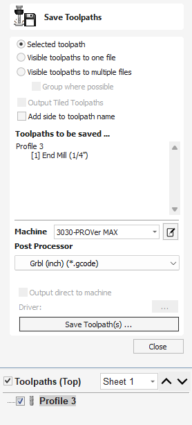
This option allows toolpaths to be saved in the appropriate file format needed to drive the CNC machine. Toolpaths can be saved as individual files for each tool used or as a single file containing multiple toolpaths for CNC machines that have automatic tool changers.
Watch this video to see this in action:
Save Option
CNC machines that require the tooling to be changed manually will typically need a separate toolpath for each cutter used. The procedure for saving this type of toolpath is to:
- Select the toolpath to save from the Toolpath List
- Click on the Save option and the Save Toolpaths form is displayed.
- Select the desired Machine from the pull-down list.
- Select one of the Postprocessors associated with that machine from the pull-down list.
- Click the Save Toolpath(s) button.
- Enter a suitable Name and click the button.
Postprocessor selection and association
When Machine is selected from drop-down list, the Postprocessor list is updated to only show those relevant for the selected machine. Before this can happen Postprocessors have to be associated with given machine.
The Postprocessors can be associated with Machine using Machine Configuration Dialog that can be accessed by clicking on
You can also select <Add Post-Processors> option from the Postprocessor drop-down list to quickly associate Postprocessors with currently selected machine.
For more details please refer to Online Machine Configuration and Manual Machine Configuration.
Selected Toolpath
Saves only the selected toolpath
Visible Toolpaths To One File
Saves all of the visible toolpaths to a single file. Requires that the selected toolpaths uses the same tool, or the use of an automatic tool changer (see below).
Visible Toolpaths To Multiple Files
Saves all of the visible toolpath to individual files. You will be prompted to provide a filename. This filename will be used as a prefix for each of the files.
If the option Group where possible is chosen then consecutive toolpaths which use the same tool will save out to the same file. In this case then the chosen name will be applied, as well as numbers which indicate which toolpaths have been saved. For example, if you decide to name your files Toolpaths and the first 3 toolpaths can be all output in single file, then that file will begin: Toolpaths_1-3 to indicate that it is toolpaths 1- 3 which are being saved out.
Automatic Tool Changing Support
CNC Machines that have Automatic Tool Changing (ATC) capabilities can work with a single file that contains multiple toolpaths, each having a different tool number.
The postprocessor must be configured to support ATC commands for your CNC machine. Contact your software or machine supplier for more details.
- The procedure for saving these toolpaths is,
- Use the Up and Down arrows to order the toolpath list in the cutting sequence required.
- Tick each toolpath to ensure it is drawn / visible in the 3D window as shown:
- Click on the Save option and the Save Toolpaths form is displayed. Select the option Output all visible toolpaths to one file
The names of the toolpaths that will be written into the file are displayed along with the tool number in square brackets [1]. If a calculated toolpath is not required, simply tick to undraw it.
Click the button Enter a suitable Name and click the button
Error Messages
The postprocessor automatically checks to ensure:
- It has been configured for saving files that include ATC commands
- A different tool number has been defined for each different cutter being used.
An error message will be displayed to indicate the problem if either of these items is not correct.
Create Text
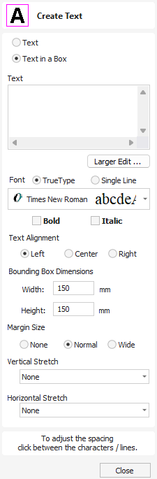
This form allows text to be created at any height using the units the model is being designed in.
Watch this video to see this in action:
Text/Text in a Box
Switch between standard Text tool and Text in a Box Tool modes.
Entering Text
To enter text:
- Click in the 2D view to choose the anchor position
- Enter the text in the Text box
- Edit the styling options. All changes are automatically applied
Font Selection
Vertical Fonts
Fonts that start with the @ character are drawn vertically downwards and are always left justified.
Engraving Fonts
The Single Line Radio Button changes the Fonts list to show a selection of fonts that are very quick to engrave.
Text Alignment
Positions text relative to the full body of text, this only has a noticeable effect when writing multiple lines of text.
Anchor
Sets the position of your text block. Either enter values directly, or use the mouse cursor to set the position values interactively:
- For new text simply left click in 2D view in the desired location
- For existing text object, left click the anchor point handle and drag it to the desired location
Text in a Box Mode
The Standard Text tools are replaced with specialist Text In a Box tools.
Watch this video to see this in action:
Bounding Box Dimensions
These are the actual size of the box into which the text will be fitted. If the text is scaled interactively (by left clicking twice on the text) or precisely using the scale tool, the new bounding box is updated and displayed as a light gray rectangle.
Margin Size
The distance between the text and the bounding box where:
- None - Scales text to fit the rectangle width or height of the bounding box
- Normal - Scales text to fit within 80% of the bounding leaving a 10% border to the left and right.
- Wide - Reduces the size to 60% of the rectangle width leaving a 20% border to the left and right.
Vertical Stretch
When the text fits the width of the box and there is space above and below it, the text can be made to fill that vertical space using one these methods:
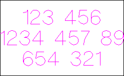
Horizontal Stretch
When the text fits the height of the box and there is space at the sides, the text can be made to fill that horizontal space using one these methods:
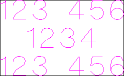
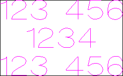
Editing Text
To edit text properties or content of previously created text:
- If the Create Text form is open, click the text you wish to edit or
- If the Create Text form is closed, click the left mouse button on the text in the 2D View to select it before opening this form. The form will now allow you to edit the properties of the selected text.
Spell Checker
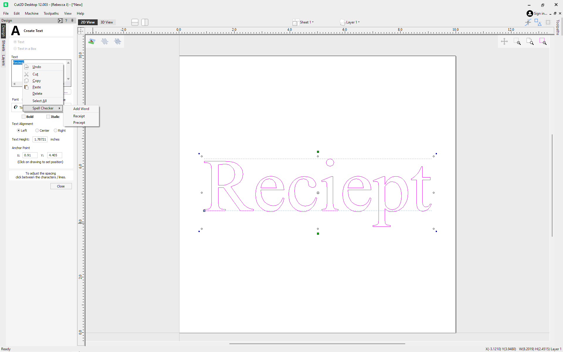
The Text tool has a spell checking feature to assist with spelling errors.
- The software checks the spelling for the user and underlines the misspelled words with red.
- When an underlined word is clicked. It suggest corrections for the user.
- There is an add word feature if you want to add a new word.
- There is a remove word feature if you want to remove a word you added by mistake ( it has to be a word added by the user).
- The language of the spell checker is the same as the language of the software.
- All the Software supported languages are supported by the spell checker except for Japanese
Usable In Both Views
This tool can be used in both the 2D and 3D View.
2D View offers a more direct way to view your vectors while 3D Offers more flexability to work with Vectors in 3D Designs and to make use of the Edit Boxes.
2D Profile Toolpath
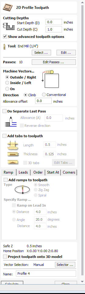
Profile Machining is used to cut around or along a vector. Options provide the flexibility for cutting shapes out with optional Tabs / bridges plus an Allowance over/undercut to ensure perfect edge quality.
Profile toolpaths can be outside, inside or on the selected vectors, automatically compensating for the tool diameter and angle for the chosen cut depth.
When working with open vectors the profile toolpaths can be to the Left, to the Right or On the selected vectors.
Clicking this icon opens the 2D Profile Toolpath form which is shown at the right; the functions in this form are described on the following pages.
If you have vectors which are nested (like the letter 'O'), the program will automatically determine the nesting and cut the correct side of the inner and outer vectors. In addition, the program will always cut the inner vectors before the outer vectors to ensure the part remains attached to the original material as long as possible.
Watch this video to see this in action:
Cutting Depths
Start Depth (D)
This specifies the depth at which the toolpath is calculated from.
When cutting directly into the surface of a job the Start Depth will often be 0. If machining into the bottom of an existing pocket or 3D region, the depth needs be entered.
Cut Depth (C)
The depth of the toolpath relative to the Start Depth.
Pass Depth Control
When a toolpath is created, the Pass Depth value associated with the selected tool (part of the tool's description) is used to determine the number of passes needed to profile down to the specified Cut Depth. However, by default the software will also modify the precise step down by up to 15% in either direction, if by doing so it is able to total number of passes required to reach the desired cut depth. It is nearly always desirable to benefit from the significantly reduced machining time of cutting using less passes if possible. Nevertheless, there are some occasions where the exact step down for a given profile pass needs to be more precisely controlled - when cutting into laminated material, for example. The Passes section page indicates how many passes will be created with the current settings.Thebutton will open a new dialog that enables the specific number and height of passes to be set directly.
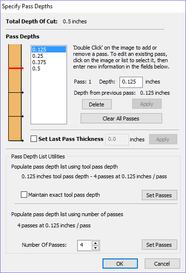
Specify Pass Depths
The Pass Depths section at the top of the form shows a list of the current pass depths. The relative spacing of the passes is indicated in the diagram next to the list. Left click on a depth value in the list, or a depth line on the diagram, to select it. The currently selected pass is highlighted in red on the diagram.
To edit the depth of the selected pass, change the value in the Depth edit box and click .
The button will delete the selected pass.
The Passes button will delete all the passes.
To add a new pass, double left click at the approximate location in the passes diagram that you wish to add the pass. A new pass will be added and automatically selected. Edit the precise Depth value if required and then click .
The Set Last Pass Thickness option will enable an edit box where you can specify the last pass in terms of the remaining thickness of material you wish to cut with the last pass (instead of in terms of its depth). This is often a more intuitive way to specify this value.
Pass Depth List Utilities
Note
Setting the number of passes with either of these utilities will discard any custom passes you may have added.
The first method simply sets the passes based on the Depth of Step property of the selected tool. By default, this is the method used by Aspire when initially creating profile passes. However, if the Maintain Exact Step Depth option is checked, the software will not vary the step size to try to optimize the number of passes (see above).
The second method creates evenly spaced passes based on the value specified in the Number of passes edit box.
To apply either method, click the Set Associated Passes button to create the resulting set of pass depths in the pass list and diagram.
Machine Vectors...
There are 3 options to choose from to determine how the tool is positioned relative to the selected vectors.
Outside

Inside

On

Direction
Can be set to either Conventional or Climb machining where the cutting direction depends upon the strategy selected - see above for details. Using Climb or Conventional cutting will largely be dictated by the material is being machined and the tooling.
Allowance offset
An Allowance can be specified to either Overcut (negative number will cut smaller) or Undercut (positive numbers will cut larger) the selected shape. If the Allowance = 0 then the toolpaths will machine to the exact size.
Do Separate Last Pass
A separate allowance can be specified for the last pass. If this allowance is given then all but the last pass will be undercut by the specified allowance with the final pass being the only pass which cuts to size.
Note
This is intended to be just a thin skin of material to be cut away as the tool will have to cut through this allowance at the full depth of the cut where all the previous passes undercut. There will be a warning displayed if the last pass allowance is greater than 1/3rd of the tool diameter but the last pass allowance should ideally be kept a lot smaller than this. Keeping this as small as possible reduces the chances the final pass will fit in areas where the previous passes will not and reduces the amount of material the last pass is having to cut through. If using a last pass allowance for the toolpath you should check that you are happy with the amount of material left for the last pass to cut through. The toolpath will fail to calculate if the last pass is cutting a significant distance into material which has not been cleared by the previous passes.
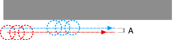
If the Reverse direction button is checked ✓ then the cutting direction of the last pass is reversed. This feature is can be useful if for minimizing witness marks on the edge of profile cuts.
The last pass allowance will also take into account any allowance offset and so the two options can be used together.
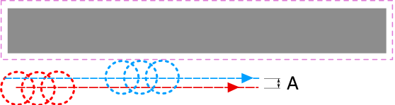
Use Vector Start Point
Use Start Point can be selected to force the toolpath to plunge and start cutting at the first point on the shape. This is very useful if you need to ensure the cutter doesn't plunge onto a critical part of the job. For example, setting the Start Point to be on a corner will often be the best position to plunge and cut from as this will not leave a witness / dwell mark on the machined surface.
The Start Points are displayed as Green boxes on all vectors when this option is selected. Start Point on a vector can be moved using the Node Editing Tools. Select Node Editing cursor or press N. Place the cursor over the node to be used as the Start Point. Click Right mouse button and select Make Start Point (or press P) Remember, you can also insert a new point anywhere on a vector using the Right mouse menu or pressing the letter P - this will insert a new point and make it the start point.
Note
Selecting Use Start Point may result in less efficient toolpaths (increased cutting times) because it may take the machine longer to move between each shape being cut. If this option is not selected the software will try to calculate the shortest toolpath, minimizing the distance between link up moves. But the downside is that the cutter may plunge/mark important surfaces on the machined edge.
Tabs (Bridges)
Tabs are added to open and closed vector shapes to hold parts in place when cutting them out of material.
Add tabs to toolpath
Checking ✓ the Add tabs option will activate tab creation for this toolpath. The Length and Thickness specify the size of each tab. Checking ✓ the Create 3D Tabs option will create 3D Tabs, the difference between this and 2D Tabs is described below.
Create 3D Tabs
When this option is selected the tab will be triangular in section. This is shape is created as the cutter ramps up to the specified Tab Thickness then down the other side. The 3D Tabs will often allow the machine to run quicker and smoother because it does not have to stop to move in Z at the start and end of each tab.
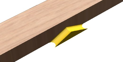
If this option is unchecked, the 2D tabs will be used. The cutter stops at the start point for each tab, lifts vertically by the specified Thickness runs across the ramp, stops and plunges down the other side.
Tab thickness is measured from the bottom of the CUT DEPTH, not the Material bottom.
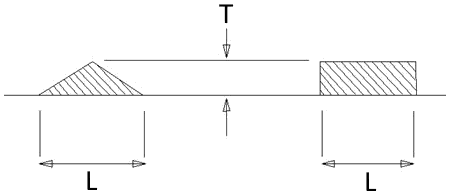
Profile Options
The Profiling options section of the toolpath form contains five additional pages, each of which allows a particular set of Profile machining options to be specified. The precise number of option pages will depend on which Toolpath strategy you are currently using. The full range of option pages are:
- Ramps
- Leads
- Order
- Start At
- Corners
These help control ways to ensure the parts are held in place and machined as easily as possible while ensuring the highest quality edge finish.
Each set of options can be accessed by the tabs at the top of the Profile options section.
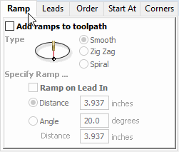
Ramp
Ramp moves are used to prevent the cutter from plunging vertically into the material. The cutter gradually cuts at an angle dropping into the material significantly reducing cutter wear, heat build-up and also the load on the router spindle and Z axis of the machine. If multiple passes are required due to the Pass Depth being less than the Cut Depth, the ramp moves are applied at the start of each level. All ramp moves are performed at the plunge rate selected for the current tool.
Smooth
This option creates a smooth ramp into the material using either the specified Distance or Angle.
When a Lead In distance has been specified, the option Ramp on Lead In disables the distance and angle options and automatically limits the ramp moves to only be on the lead in portion of the toolpath.
Zig Zag
This option ramps into the material by Zig-Zag backwards and forwards using either the specified Distance or Angle and Distance.
The Distance option ramps into the material, zigging for the specified distance in one direction then zagging back over the same distance.
The Angle option is typically used for cutters that cannot plunge vertically but have an entry angle specified by the manufacturer.
Spiral
Checking ✓ this creates a continual spiral ramp, these are only available when the toolpath does not include lead in moves.
This option ramps into the material over the complete circumference of the profile pass. The angle is automatically calculated to ramp from the start point to full depth over the perimeter distance around the job.
The rate at which the cutter ramps into the material is determined by the Pass Depth specified for the cutter. For example, Spiral Profiling 0.5 inch deep with a cutter that has a Pass depth of 0.5 or greater will spiral down in 1 pass. Editing the Pass depth to be 0.25 inch results in the 2 spiral passes around the profile.
Leads
Lead in / out moves can be added to profile toolpaths to help preventing marking the edges of components with dwell marks that are typically created when a cutter is plunged vertically on the edge of the job.
Straight Line Lead
This option creates a linear lead onto the cutter path using the Angle and Lead length distance specified.
The toolpath will lead onto the selected edge at the specified Angle.
Checking ✓ the Do lead out option results in an exit lead being added at the end of the toolpath off the machined edge.
The Overcut Distance forces the cutter to machine past the start point and is often used to help produce a better edge quality on parts.
Circular Lead
This option creates an arc lead onto the toolpath using the Radius and Lead length distance specified.
The Radius and Angle will automatically inform the Length when entered, and the angle range is 0.1 to 90 degree.
The toolpath will curve onto the selected edge, tangent to the direction of the vector at the point it reaches the actual geometry edge.
Checking ✓ the Do lead out option results in an exit lead being added at the end of the toolpath off the machined edge.
The Overcut Distance forces the cutter to machine past the start point and is often used to help produce a better edge quality on parts.
Order
The order tab allows you to specify the approaches the program will use to determine the best order to cut your vectors. You can specify multiple options, in which case the program will calculate the result of using each option and select the one which results in the shortest machining time.
Vector Selection Order
This option will machine the vectors in the order in which you selected them. If you have vectors inside each other (like in the letter 'O'), the inner vector will always be machined before the outer one regardless of the selection order.
Left to Right
This option will join up parts on the left of the material first and move across to the right.
Bottom to Top
This option will join up parts on the bottom of the material first and move up to the top.
Grid
This option will join using a grid based approach with the size of the grid based on the size of the parts. The algorithm will try to join up parts within a particular section of the grid before moving on.
Start At
Keep Current Start Points
The start point of the vector will dictate the start of the toolpath.
Optimize Start Points
The software will automatically attempt to optimize each profile start position based on speed of completing the job.
Closest on Bounding Box
Influence the start point by defining which part of the bounding box of the profiled vector it should start near.
This will look for the nearest point, from all of the spans' endpoints, and will start the toolpath from that point.
Position and Selection Properties
Safe Z
The height above the job at which it is safe to move the cutter at rapid / max feed rate. This dimension can be changed by opening the Material Setup form.
Home Position
Position from and to that the tool will travel before and after machining. This dimension can be changed by opening the Material Setup form.
Project toolpath onto 3D Model
This option is only available if a 3D model has been defined. If this option is checked, ✓ after the toolpath has been calculated, it will be projected (or 'dropped') down in Z onto the surface of the 3D model. The depth of the original toolpath below the surface of the material will be used as the projected depth below the surface of the model.
Note:
When a toolpath is projected onto the 3D model, its depth is limited so that it does not exceed the bottom of the material.
Vector Selection
This area of the toolpath page allows you to automatically select vectors to machine using the vector's properties or position. It is also the method by which you can create Toolpath Templates to re-use your toolpath settings on similar projects in the future. For more information, see the sections Vector Selector and Advanced Toolpath Templates.
Name
The name of the toolpath can be entered or the default name can be used.
Chamfer Toolpath
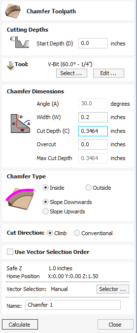
The Chamfer Toolpath uses the selected vectors and tool to create an angled feature
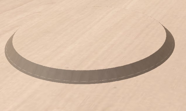
The Chamfer Toolpath has two distinct ways of operating depending on the tool used:
- If the selected tool is an angled tool, then the angle of the tool determines the angle of the chamfer
- If the selected tool is a round nosed tool, then the angle of the chamfer must be specified manually, and will be approximated by a series of fine cuts.
Watch this video to see this in action:
Cutting Depths
The Start Depth (D) specifies the depth at which the top of the chamfer should start.
Vector Selection
To create the toolpath you must first draw and then select the vectors you wish to create the chamfer on.
Tool
Clicking the button opens the Tool Database from which the required tool can be selected. See the section on the Tool Database for more information on this. Clicking the button opens the Edit Tool form which allows the cutting parameters for the selected tool to be modified, without changing the master information in the database. Hovering the mouse cursor over the tool name will display a tool tip indicating where in the Tool Database the tool was selected from.
Chamfer Dimensions
The chamfer dimensions control the shape of the created chamfer.
Angle (A)
The angle determines the slope of the chamfer. It is measured from vertical.
When a V-Bit tool is selected for the toolpath then the angle is fixed to half of the angle of the tool.
For a round nosed tool then the angle may be specified.
Width (W)
The width determines the horizontal size of the chamfer. If the angle is set then changing the width will change the cut depth proportionally.
Cut Depth (C)
The Cut depth is the height of the chamfer. If angle is set then changing the cut depth will change the width proportionally.
Max Cut Depth
To achieve the desired height of the chamfer, as specified by the cut depth field, cutting deeper might be required. This will be true in the case of a round-nosed tool.
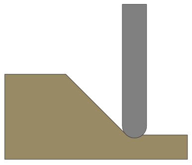
The Max Cut Depth field is read only and shows the full length of the cut so you can accurately see how deep the tool cuts.
Overcut
When using a V-Bit tool for chamfering it can be desirable to use the edge of tool, and keep the point of the tool off the part. Small movements in the machine and the material can mean that the point of the leaves an unsightly witness mark. The overcut control allows you to specify a value that will be used to offset the centre of the tool, and use the side of the tool for machining.
Note
The length of the side of the tool is unknown and so when specifying an overcut distance you should always ensure that the cutting edge of the tool is long enough to accomodate the overcut distance.
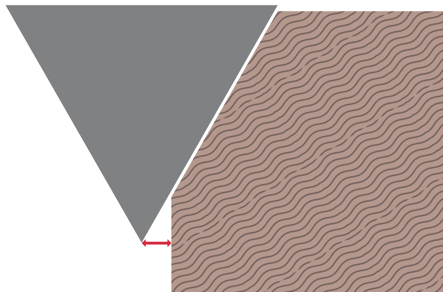
Chamfer Type
The Chamfer Type option controls whether or not a chamfer occurs inside or outside a vector and the direction of the chamfer slope :
- An inner chamfer will be inside the selected vector.
- An outside chamfer will be outside the selected vector.
The direction of the slope tells us whether our chamfer is upward or downward relative to the selected vector or whether it is downward relative to the selected vector.
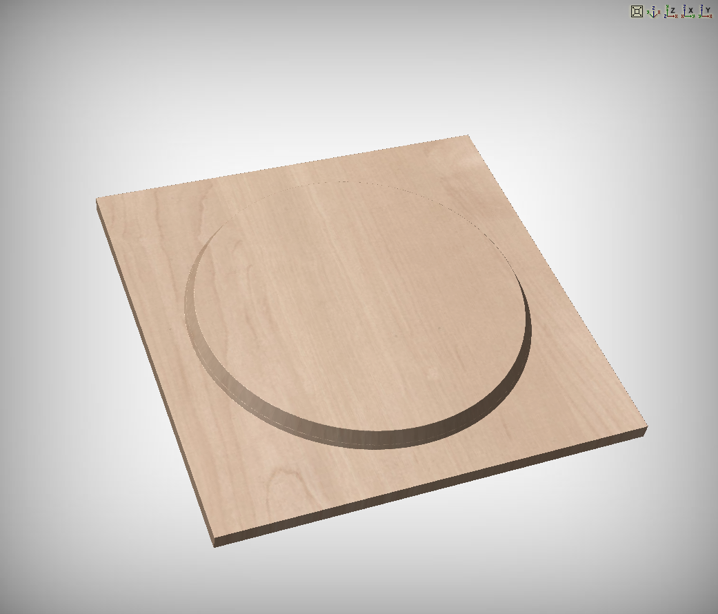
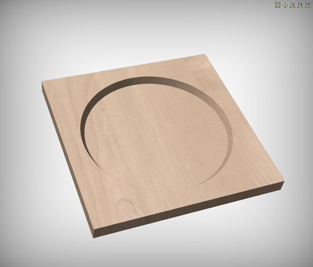
Both options can be used together to generate different chamfer styles.
Cut Direction
The cut direction may be set to either climb or conventional milling.
2D Preview
When using the Chamfer toolpath the 2D View will provide immeditate feedback on what the resulting chamfer will look like. Small lines will extend outwards from the selected vector to show where the slope of the chamfer will lie. The arrows on these line indicate the direction of slope. The arrows always point down in the direction of the downwards slope.
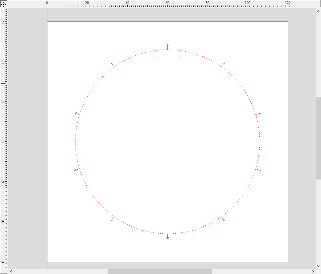
Use Vector Selection Order
If this option is checked, ✓ the vectors will be machined in the order you selected them. If the option is not checked the program will optimize the order to reduce machining time.
Position and Selection Properties
Safe Z
The height above the job at which it is safe to move the cutter at rapid / max feed rate. This dimension can be changed by opening the Material Setup form.
Home Position
Position from and to that the tool will travel before and after machining. This dimension can be changed by opening the Material Setup form.
Vector Selection
This area of the toolpath page allows you to automatically select vectors to machine using the vector's properties or position. It is also the method by which you can create Toolpath Templates to re-use your toolpath settings on similar projects in the future. For more information, see the sections Vector Selector and Advanced Toolpath Templates.
Name
The name of the toolpath can be entered or the default name can be used.
Load Toolpath Template
When you load a previously saved toolpath template (using Toolpaths ► Templates ► Load Template...) you will have an empty toolpath which can be edited by double clicking on its name in the toolpath list or selecting the Edit Toolpath icon in the Toolpaths tab. Once the toolpath form is open, the vectors to be machined can be selected and the toolpath calculated using all the saved settings.
If you load a toolpath template which has toolpaths associated with layers which don't exist in the current file, the Missing Layers for Template dialog will be displayed. It lists all the missing layers and offers you the choice of having them created automatically, deleting toolpaths associated with missing layers or just loading the toolpaths as is.
Choosing to allow the dialog to automatically create the missing layers allows a toolpath template to be used to create 'standard' layers for machining operations and load the toolpaths ready to be calculated. All you then need to do is move vectors to the appropriate layers and recalculate all the toolpaths.
Choosing the Delete all toolpaths associated with missing layers option allows you to create a single template with many toolpaths and have the ones which aren't appropriate to the current job automatically deleted.
Multiple Sheets
If a Template is loaded into a project with multiple sheets in the project, it will offer to apply that template to all sheets in the project.
Estimating Machining Times
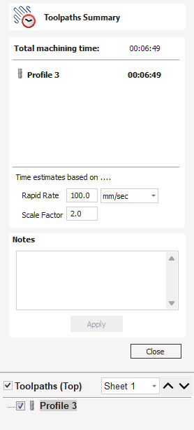
This option estimates the machining times for all calculated toolpaths based on the feed rates specified for each tool. The estimates for individual toolpaths plus the overall machining time of all visible toolpaths are calculated using the user defined Rapid Rate moves and Scale Factor.
Times
The estimated machining times are displayed in Hours: Minutes: Seconds
Rapid Rate
The maximum feed rate at which the machine runs for rapid moves, typically specified using a G0 or G00 move
Scale Factor
The nature of different styles of toolpaths means that they may be simple 2D cuts or require simultaneous 3-axis moves, the more complex the toolpath then the more chance the CNC machine may not actually achieve the programmed feed rates. This can be compensated for by multiplying the times by the Scale Factor.
The scale factor in the program lets you approximate this slowdown for your machine, but it will vary depending on the type of work you are doing. Many people will use one scale factor for simple 2d work and another for 3d or VCarving. The best way to calculate it is just to take a note of estimated and actual machining times of a period of time.
For machines where the controller provides an estimated machining time, these should be more accurate as the controller can determine where the machine is accelerating / decelerating and take account of this.
Notes
Notes for the summary of the toolpath can be written here.
Click Apply once written to store them.
2D View Controls
See also the Rulers, Guides and Snap Grid section.
 | Pan | Click and hold the Left mouse button and drag the mouse about to Pan - Esc to cancel mode Shortcut: Click and drag the Middle mouse button or if using a 2 button mouse, Hold Ctrl + drag with Right Mouse button. | |
 | Zoom Interactive | Mouse with Middle Wheel - Scroll wheel in / out Mouse without Middle Wheel - Hold Shift + Push / Pull with Right Mouse button. | |
 | Zoom Box | Click top left corner, hold mouse down and drag to bottom right corner and release. Clicking the left mouse button will zoom in, Shift + click will zoom out. | |
 | Zoom Extents | Zooms to show material limits in the 2D window | |
 | Zoom Selected | With objects selected Zooms to the bounding box of the selection |
Sheets
When there are multiple sheets in the job then the outline of the sheets is shown in the 2D view.
Here you can see Sheet 1 Is the Active Sheet.
When vectors lie outside of the bounds of a sheet, then the bounds in the 2D view are updated to indicate this.
A sheet can be activated by using the Sheet Management Tab, using the Sheets Dropdown menu, or by double clicking on the sheet in the 2D view.
Undo Operation
Clicking this option steps backwards through the design changes made by the user.
Draw Arc
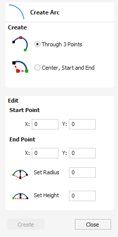
The Create Arc tool allows a single arc span to be created using precise values, or dynamically within the 2D View.
Watch this video to see this in action:
Through 3 Points
- Left click the mouse in the 2D View to set the start point of an arc.
- Click again to set the end point position.
- Move the mouse and click a third point to set the arc's radius.
Center, Start and End
- Left click the mouse in the 2D View to set the center point of the arc.
- Click again to set the start point of the arc.
- Move the mouse and click a third point to set the end point of the arc.
Note
Clicking the Right mouse button will complete the arc drawing if possible and close the form. Pressing the Esc key will close the form.
Exact Size
Precise values for the start and end point positions (in absolute X Y coordinates) and either the radius or the height of the arc can be entered in the form directly. Click to draw an arc using these values.
Material Setup
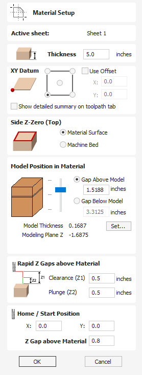
The Material Setup section of the Toolpaths tab provides a summary of the current material settings. Some of these values will have been initially set when the job was first created (see Job Setup for more information). When you come to creating toolpaths, it is important to review this information and ensure it is still valid and also to set the machining clearances. To access all these properties for editing, click on the button to open the Material Setup form:
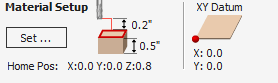
Different form is displayed depending on the job type:
Watch this video to see this in action:
Toolpath Tiling Manager
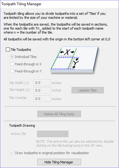
Using the Toolpath Tiling options it is possible to machine objects and designs that are many times larger than the available area of your CNC machine bed. This process is also invaluable if the maximum size of your material pieces are limited. In both cases, a much larger project can still be achieved by breaking the toolpath down into manageable tiles or strips, each of which can fit within the machinable area of your CNC machine, or on the available material blocks. Once cut, the tiles can then be re-assembled to form the finished piece.
The process of tiling begins by creating toolpaths based on the final object entirely as normal - at this stage you do not need to take any account of the available machining bed size. Once you have calculated required toolpaths, click on the toolpath tiling button in the toolpaths pane to open up the toolpath tiling form.
Tiling Options
There are three layout strategies for tiled toolpaths, the most appropriate one will depend on your machines capabilities and the available material.
Individual Tiles
The first tiling option is for individual tiles. This splits the current job in both X and Y, to form a series of entirely separate toolpaths. This is generally the preferred option if you have independent pieces of material to machine, or if you have a moving-bed type CNC machine that will not allow you to 'overhang' material outside of the machinable area.
With this option selected, you are asked to specify the width and height of each tile, and the required overlap (which will be applied in each direction). Tiles are created from the bottom left of your model. The overlap for independent tiles is particularly important for 2.5D toolpaths that utilize the shape of your tool bit (such as V-bit carving). 2.5D toolpaths will need to 'overrun' the edges of your tile in order to complete their cuts using the side of the bit. For this reason, the overlap distance for Independent Tiles will typically need to be at least equal to the radius of your tool bit.
Feed-through in X or Feed-through in Y
Instead of cutting a series of individual pieces of material and assembling them later, it can also be convenient to cut a single strip of material using a series of set-ups - moving the material through the machinable area between cuts. Aspirespecifically supports this technique using the Feed-through in X/Y options. In these cases you will only need to define either the Tile Width or Height (which corresponds to your intended feed-through distance), as the other dimension is assumed to correspond to the shorter side length of your material and will match the equivalent current job dimension. Similarly, the overlap distance is only applied in the direction of the draw-through. Because you will typically be cutting the same piece of material with each toolpath tile, the overlap distance for Feed-through is not as critical as for Individual tiles and is typically used to allow for a margin of error in your set-up accuracy.
Once you have set your tiling option, click the Update Tiles button to see your settings reflected in the Tile Previews in either the 2D or 3D Views.
Machine smallest tile first
If this option is unchecked then the tiling space is divided into parts of the specified size. Any remainder space is placed at the end. If the option is checked then the remaining space is placed at the beginning.
Tile Previews
The 2D View indicates how the model area is split into tiles. The yellow lines indicate the tile sizes, but the light red areas also indicate the overlap region for each tile.
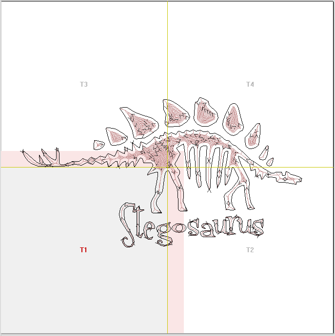
Double-clicking on a tile will make that tile the active tile.
In the 3D view the toolpaths will be showed tiled, with only the moves that are within the active tile shown.
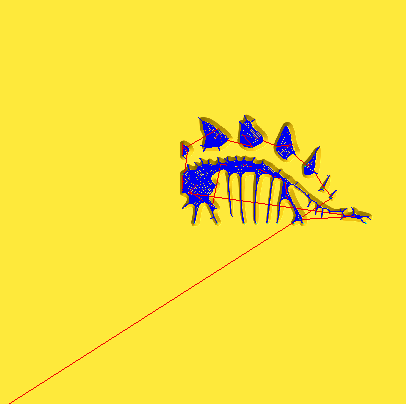
Simulating Tiled toolpaths
You can also view and simulate individual toolpath tiles in the 3D View. To view the toolpath tiles, simply ensure that the toolpaths are visible (checked ✓ in the Toolpath List) and then select the tile you wish to see either from the Tile Toolpaths form, or the 2D View (see above).
Since tiles are created so that they will all be cut within the same machinable area (i.e. they are all located in a similar position relative to the machining origin), this can make them difficult to visualize using Preview Toolpaths. Simulating each toolpath tile in its absolute position will result in the toolpaths being cut in the same region of your preview block and they will overcut the same area. The Tile Toolpaths form has an option Draw toolpaths in original position for visualization to allow you to simulate the tiles as if they were arranged in their final pattern. With this option enabled, you can visualize how your final piece will look by previewing all your toolpath tiles together, but you should note that it will not reflect the true offset of each toolpath from your machining origin.
Saving toolpath tiles
Provided you have created toolpath tiles using the Tile Toolpaths form, an additional option, Output Tiled Toolpaths, will be available in the toolpath saving form.
It will be checked ✓ or unchecked to match the current state of the Tile Toolpaths check box in the Tile Toolpaths form.
06. Intermediate - 2D Design and Management
The 2D View is used to design and manage the layout of your finished part. Different entities are used to allow the user to control items that are either strictly 2D or are 2D representations of objects in the 3D View. A list of these 2D View entities are described briefly below and more fully in later sections of this manual.
Ultimately the point of all these different types of objects is to allow you to create the toolpaths you need to cut the part you want on your CNC. This may mean that they help you to create the basis for the 3D model or that they are more directly related to the toolpath such as describing its boundary shape. The different applications and uses for these 2D items mean that organization of them is very important. For this reason Aspire has a Layer function for managing 2D data. The Layers are a way of associating different 2D entities together to allow the user to manage them more effectively. Layers will be described in detail later in the relevant section of this manual. If you are working with a 2 Sided project you can switch between the 'Top' and 'Bottom' sides in the same session, enabling you to create and edit data on each side, and using the 'Multi Sided View' option you can view the vectors on the opposite side. 2 Sided Setup will be described in detail later in the relevant section of this manual.
Vectors
Vectors are lines, arcs and curves which can be as simple as a straight line or can make up complex 2D designs. They have many uses in Aspire, such as describing a shape for a toolpath to follow or creating designs. Aspire contains a number of vector creation and editing tools which are covered in this manual.
As well as creating vectors within the software many users will also import vectors from other design software such as Corel Draw or AutoCAD. Aspire supports the following vector formats for import: *.dxf, *.eps, *.ai, *.pdf, *skp and *svg. Once imported, the data can be edited and combined using the Vector Editing tools within the software.
Bitmaps
Although bitmap is a standard computer term for a pixel based image (such as a photo) in *.bmp, *.jpg, *.gif, *.tif, *.png and *.jpeg. These file types are images made up of tiny squares (pixels) which represent a scanned picture, digital photo or perhaps an image taken from the internet.
To make 3D models simple to create, Aspire uses a method which lets the user break the design down into manageable pieces called Components. In the 2D View a Component is shown as a Grayscale shape, this can be selected and edited to move its position, change its size etc. Working with the Grayscale's will be covered in detail later in this manual. As with bitmaps, many of the vector editing tools will also work on a selected Component Grayscale.
Interactive Selection Mode
The Interactive Move, Rotate, Scale Selection tools can be used to quickly and easily modify vectors and components.
Watch this video to see this in action:
Clicking twice on one of the selected objects and the interactive scaling, movement and rotation handles are displayed in the same way as selecting this icon. Lines, Arcs and Bezier spans will be displayed as dotted magenta lines and text and grouped objects will be displayed as solid magenta lines:
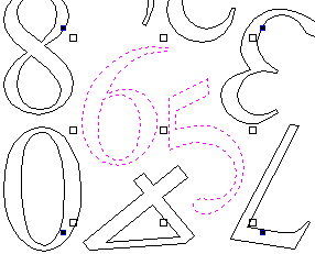
Transform Handles
When in this mode the mouse is used to click on one of the handles which has appeared on the selected Vector/s. Each Transform handle is used for a specific editing operation as detailed here in the 2D View:
- Middle - Move the vectors (Hold +Alt Move the selected objects in one axis)
- Middle - Click a second time to switch to Rotational center. Click and drag the Rotational Anchor to reposition the Rotational Center of the current selection.
- Corner (White) - Scale the vectors proportionally (Hold +Alt Scaling non-proportionally, +Shift Scale around the centre)
- Edges (White) - Scale the vector in one axis (Hold +Shift Scaling proportionally)
- Corner (Black) - Rotate the vectors (Hold +Alt Rotate in 15° increments) about the Rotation Center.
To deselect objects,
- Click the white background unless Shift is pressed.
- Press Esc
- Right click menu ► Unselect All
In the 3D View, the Transform Handles are:
- Middle - Move the vectors (Hold +Alt Move the selected objects in one axis)
- Middle - Click a second time to switch to Rotational center. Click and drag the Rotational Anchor to reposition the Rotational Center of the current selection.
- Corner (White) - Scale the vectors proportionally (Hold +Alt Scaling non-proportionally, +Shift Scale around the centre)
- Edges (Black) - Scale the vector in one axis (Hold +Shift Scaling proportionally)
- Rotation Arrow (Top Black) - Rotate the vectors (Hold +Alt Rotate in 15° increments)
When you select a Transform Handle, it will activate the appropriate Edit Box for that Handle.
If you need an exact value for a Transformation, click into this box and type in the desired value, followed by Enter to accept the new value.
Usable In Both Views
This tool can be used in both the 2D and 3D View.
2D View offers a more direct way to view your vectors while 3D Offers more flexability to work with Vectors in 3D Designs and to make use of the Edit Boxes.
Sketch Carving
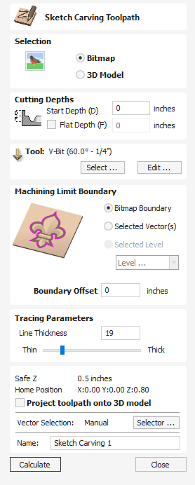
This tool uses the differences in contrast between areas of a Bitmap image or a 3D model to create a toolpath and create a Sketching style carving design of the outline.
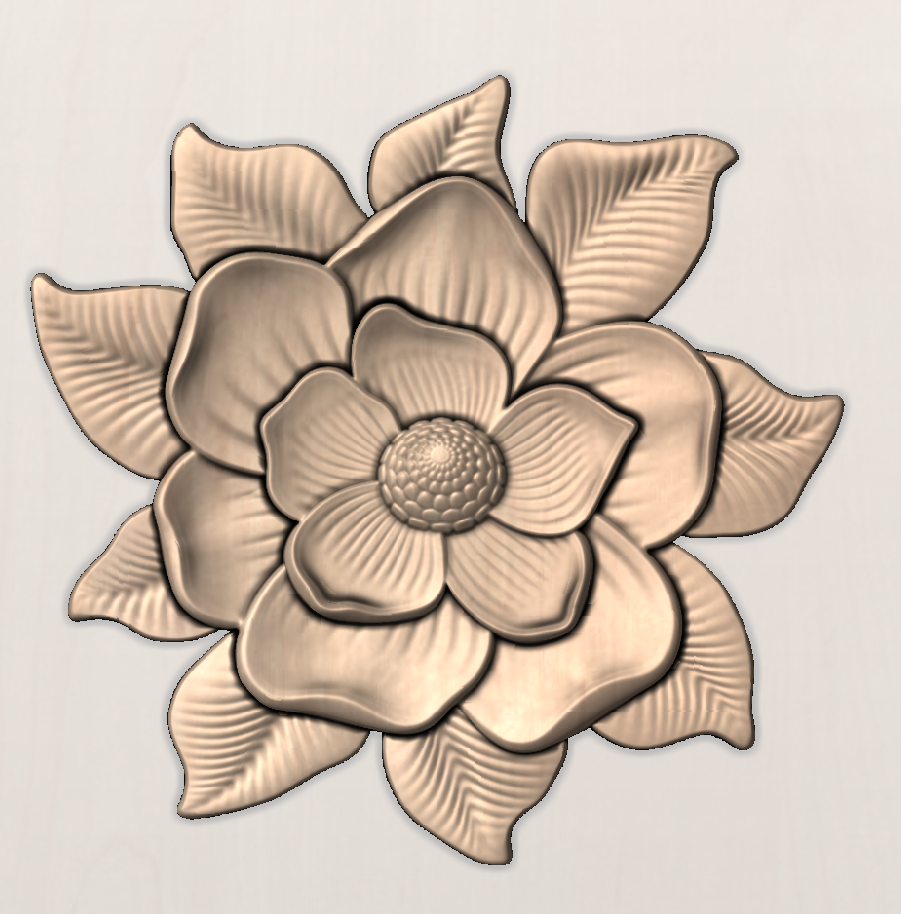
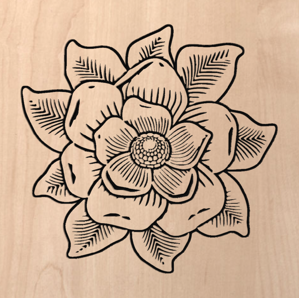
Watch this video to see this in action:
Selection
This allows the User to indicate if the selecting image is either:
Bitmap
An image file Imported in the following format .BMP, .JPG, .GIF, .TIF, .TIFF, .PNG, .JPEG
3D Model
A 3D file import in the following format .STL, .V3M, .3DM, .SKP, .RLF, .3DS, .ASC, .PRJ, .X, .DXF, .LWO, .WRL, .OBJ
Cutting Depths
Start Depth (D)
This specifies the depth at which the toolpath is calculated from.
When cutting directly into the surface of a job the Start Depth will often be 0. If machining into the bottom of an existing pocket or 3D region, the depth needs be entered.
Cut Depth (C)
The depth of the toolpath relative to the Start Depth.
Tool
Clicking the button opens the Tool Database from which the required tool can be selected. See the section on the Tool Database for more information on this. Clicking the button opens the Edit Tool form which allows the cutting parameters for the selected tool to be modified, without changing the master information in the database. Hovering the mouse cursor over the tool name will display a tool tip indicating where in the Tool Database the tool was selected from.
Machine Limit Boundary
Choose what to use as the outer boundary for the Sketch Carving toolpath
Bitmap Boundary
Using the external edge of the bitmap or 3D file as the boundary for the tools operation.
Selected Vector
Allows a vector to be used as a boundary to limit the extent of the toolpath creation.
Hold SHIFT and selected the desired Vector to use as the boundary after selecting the Bitmap or 3D model you are Sketch Carving.
Selected Level
Allows a Component Level to be selected to use the components on that level for a boundary to limit the extent of the toolpath creation.
Boundary Offset
Increase the Machining limit outside of the boundary selected above but the distance used here. The Default value is 0.
Tracing Parameters
The Line Thickness slider will allow you to adjust the weighting of your sketch lines created from your 3D model or Bitmap image.
This can slide between 0 and 100.
The higher the value the thicker and heavier the sketch carve lines will be but the less detail will be picked out.

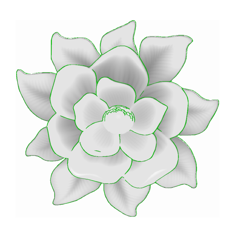
You can see here the green hightlighted area shows the area which will be cut in this toolpath, with the lower Line Thickness picking out more lighter details, but overall cutting a much shallower area, while the Thicker Line Thickness will apply more heavily to the largest areas while not cutting the finer details.
By reviewing the Sketch Carves Green Highlights you can get a good idea how the toolpath will cut before calculating it.
Position and Selection Properties
Safe Z
The height above the job at which it is safe to move the cutter at rapid / max feed rate. This dimension can be changed by opening the Material Setup form.
Home Position
Position from and to that the tool will travel before and after machining. This dimension can be changed by opening the Material Setup form.
Project toolpath onto 3D Model
This option is only available if a 3D model has been defined. If this option is checked, ✓ after the toolpath has been calculated, it will be projected (or 'dropped') down in Z onto the surface of the 3D model. The depth of the original toolpath below the surface of the material will be used as the projected depth below the surface of the model.
Note:
When a toolpath is projected onto the 3D model, its depth is limited so that it does not exceed the bottom of the material.
Vector Selection
This area of the toolpath page allows you to automatically select vectors to machine using the vector's properties or position. It is also the method by which you can create Toolpath Templates to re-use your toolpath settings on similar projects in the future. For more information, see the sections Vector Selector and Advanced Toolpath Templates.
Name
The name of the toolpath can be entered or the default name can be used.
Tool Database - Custom Naming Variables
In addition to the pre-set Variables list, the user also has the option to define their own custom Variables which may use other attributes of the tool that are not possible to include within our default tool naming convention. This could then be used to better assist the user in distinguishing one tool from another at a glance. For example, you could choose to include the tool manufacturer, purpose and material as a variable which can be applied to individual or full groups of tools.
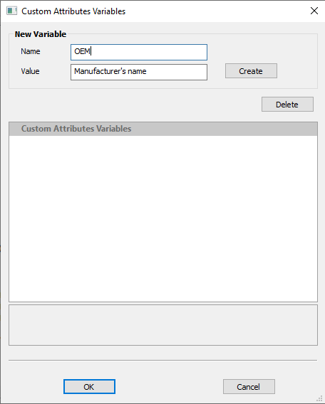
Creating Custom Variables
The Custom Attributes variables form is accessible from within the tool database.
1. Open the tool database through clicking the tool database button within toolpaths panel or though; Toolpaths (In menu bar) > Tool Database
2. Select the specific tool you would like to create custom Variables for and then Click The ‘Variables’ button to the Right of the notes field in the main tool geometry section of the form, to open the ‘Custom Attributes Variables’ form.
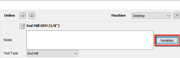
3. At the very top of the form under ‘New Variable’ you will see two edit boxes;
- Name – This is the title of the Variable, and specifies the expression you would need to enter within the tool name field to achieve the required Value.
- Value – This is the resulting text which replaces the corresponding user defined expression when entered into the tool name field.
This means that if you require X Value within the tool name then you would need to enter Name Y within curly Brackets {Y}. Y is defined by the Name field of the Custom attributes Variables form.
4. Click the ‘Create’ button to the right of the edit boxes to apply changes and to create the custom variable, then Okay to close out of the form.
Applying Custom Variables
- Click the ‘Edit’ button next to the tool name above the notes field.
- Place cursor where you would like to place value within string
- Right click > Custom Attributes variables > Search and select correct name in list.
Note
Custom variables should be created and then selected from the list rather than entered manually with prefix. This is to prevent conflict with the software’s own pre-set variables. The purpose of custom variables is purely organisational, they cannot action an effect on tool parameters or toolpath output.
- Click ‘Ok’ at the bottom of the form to apply changes.
Deleting Variables
To delete a variable you will need to first delete this value from each tool you have applied it to before deleting the variable title itself.
Import Bitmap / Vectors
This opens the File Open dialog window and allows 2D Vector DXF, EPS and AI and PDF files to be imported into the 2D View. The imported vectors will always be read in at the size and scale they were created in their original design software. Once open they can be scaled and edited in the same way as vectors created in Aspire. All the Vector tools will be dealt with in that section of this manual.
It also allows image files to be selected and imported into the current open job. File types - BMP, JPG, TIF, GIF, PNG
Images are imported to sketch vectors over the top of them, generate traced vectors or to be used to generate a 3D Component directly from the image when using Aspire. These functions will be covered in more detail in the Modelling section of the Design tools.
To import toolpaths from PhotoVCarve and Cut3D (.PVC and .V3D file extensions), use File ► Import... ► Import PhotoVCarve or Cut3D Toolpaths from the file menu bar. Any Toolpath data saved as .PVC or .V3D files can be imported and will be visible in the Toolpath List.
See the 3D Toolpath Files section for detailed instructions on importing PhotoVCarve(*.pvc), Cut3D(*.v3d) or Vectric 3D Machinist(*.v3m) files.
09. Intermediate - Simple Rotary Modelling using 2D Toolpaths
Creating vectors for a basic column
This section will show how to create a simple column, using the profile and fluting toolpaths.
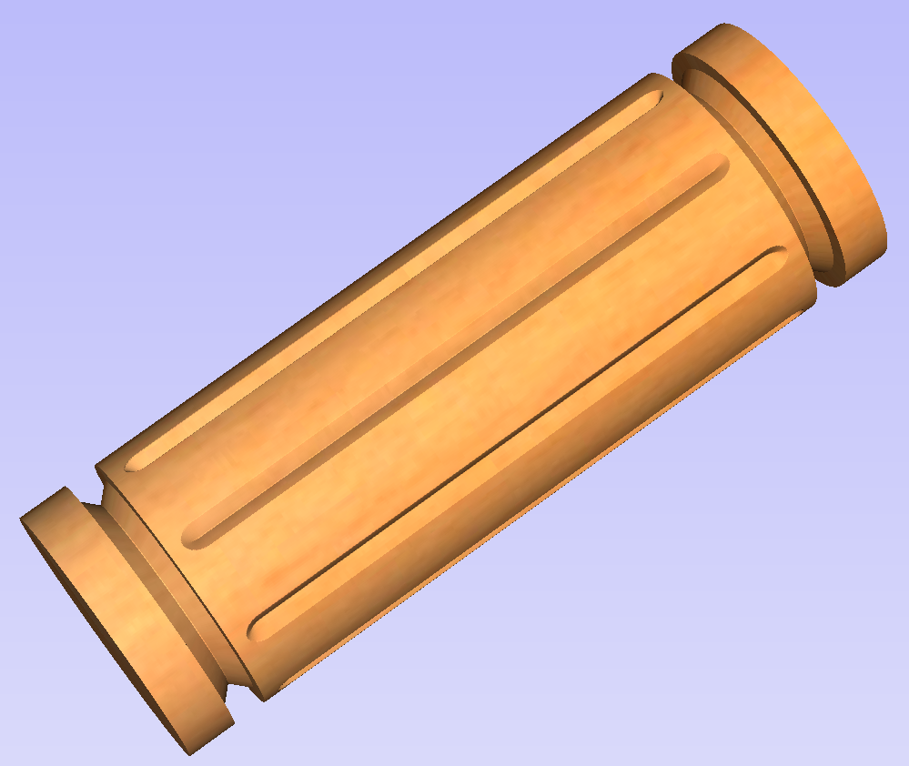
Start by creating a new rotary job. Please note that settings shown here are only an example and should be adapted to match your machine setup and available material.
In this example the blank will rotate around X axis. We will refer to it as the rotation axis. The axis that will be wrapped is the Y axis. We will refer to it as the wrapped axis. That means that the top and bottom boundaries of the 2D workspace will actually coincide. We will refer to them as the wrapped boundaries.
First, create the cove vectors using Draw Line/Polyline tool. Those will run along the wrapped axis at both ends of the design. Snapping may be useful to ensure that the created line starts and ends at the wrapped boundaries.
In this example the coves were placed 1 inch from the job boundaries, leaving 10 inches in the middle for the flutes. The flutes will run along rotation axis. Assuming 0.5 inch gap between the cove and the beginning of the flute, the flutes will have the length of 9 inches. This example will use 8 flutes.
To start, create a line parallel to rotation axis that is 9 inches long. Now select the created flute vector and then select one of the cove vectors while holding down Shift. Then use Copy Along Vectors tool to create 9 copies. The original flute vector may now be removed as it is no longer necessary. Note that first and last copy are both created on wrapped boundaries. That means they will coincide, so one of them can be removed. As the last step select all flute vectors and press F9 to place them in the center of design.
Creating rotary toolpaths
The process of creating 2D rotary toolpaths is very similar to creating toolpaths for Single - and Double - models. This example will use the profile toolpath on the cove vectors. To create the toolpath, select the cove vectors and click on the Profile Toolpath from
To create the toolpath for the flutes, select the flute vectors and click on the Fluting Toolpath. This Example used a 1 inch 90deg V-Bit set to Flute Depth 0.2 and using the Ramp at Start and End and Ramp Type Smooth options. Ramp length was set to 0.25 inches. Both toolpaths can be seen below.
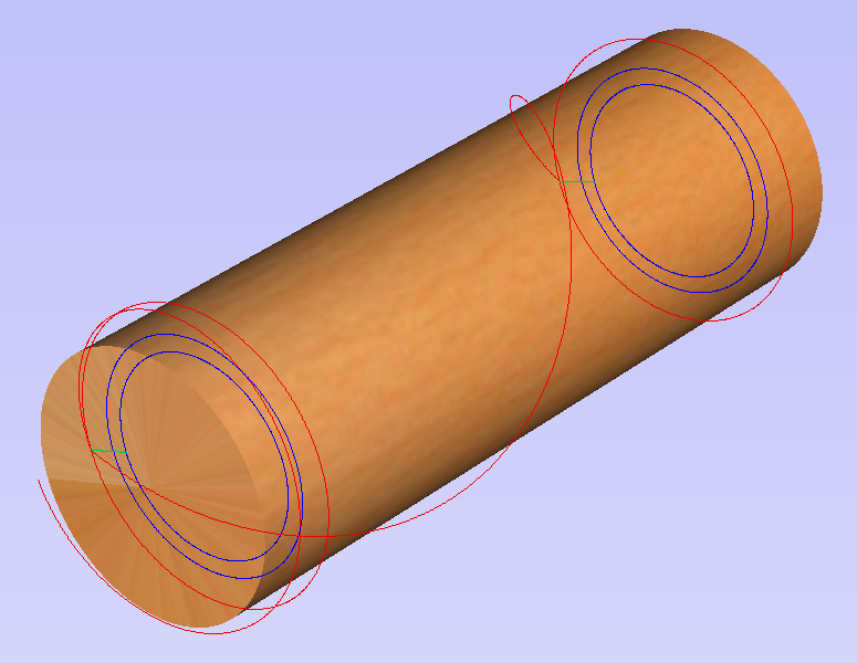
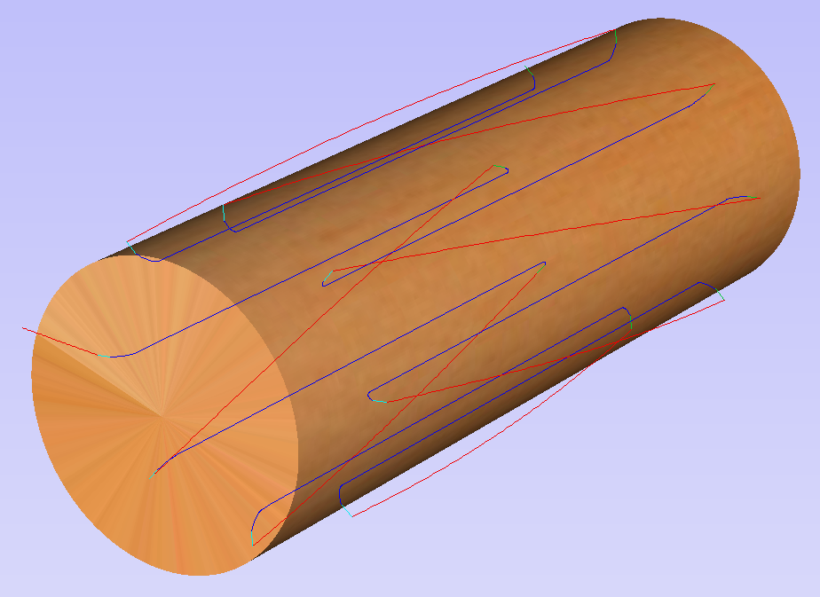
Simulating and saving toolpaths
It is time to simulate toolpaths using Preview Toolpaths. If the option to animate the preview is selected, the simulation will be visualized in flat mode. Once the simulation is complete, the wrapped rotary view will be turned back on automatically.
Contrary to single - and double - sided simulation, rotary simulation is not 100% accurate. For example round holes will appear in rotary view as oval ones, but obviously will be round when part is actually machined.
Although the design can be considered to be finished, in practice it is useful to be able to cut-out the remaining stock. This can be realized by making the design slightly longer and adding profile cuts. In this example the blank length was extended by 2 inches using the Job Setup . Existing vectors can be recentered using F9After that the existing toolpaths have to be recalculated.
The cut-out vectors can be created in the same way as cove vectors. Two extra profiling toolpaths can be created using the suitable End Mill. In this example we used a tab with a 0.5 inch diameter. In order to achieve that, the user can type the following in the Cut Depth box: z-0.25 and then press = and the software will substitute the result of the calculation. Variable 'z' used in the formula will be substituted by the radius of the blank automatically by software. It is also important to specify Machine Vectors Outside/Right or Machine Vectors Inside/Left as appropriate. The cut-out toolpaths and the resulting simulation can been shown below.
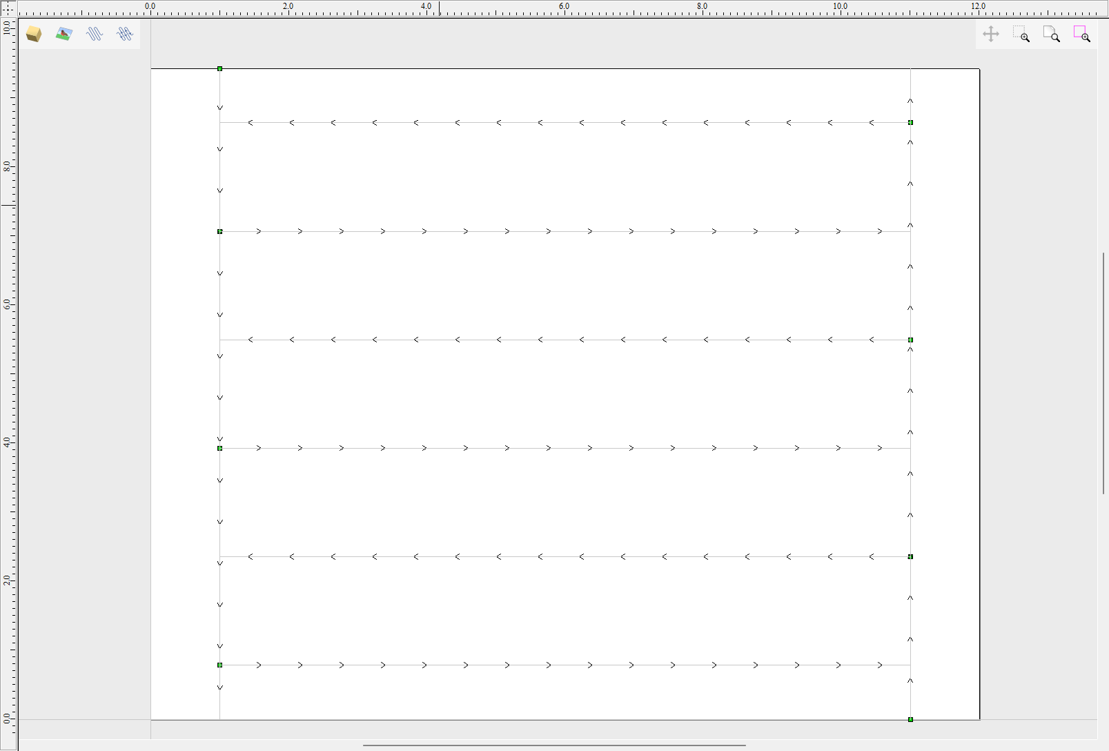
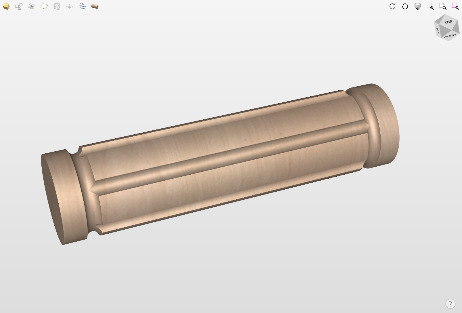
The final step is to save the toolpaths in a format acceptable by your machine. Use the Save Toolpaths and select the wrapped post-processor matching your machine.
Note
Tools and values presented in this example are for illustrative purposes only. Size of tools, feed rate, tabs diameter etc. have to be adapted to the material and machine used to ensure safe and accurate machining.
Spiral toolpaths
This section will explain how to create and simulate spiral toolpaths.
One way of thinking about spiral toolpaths is to imagine a long, narrow strip of fabric. Such a strip can be wrapped around a roll at a certain angle. In order to create a toolpath that wraps around the blank multiple times, one can create a long vector at a certain angle. Such a vector is an equivalent to the strip of fabric when it is unwrapped from the roll.
Although such a toolpath will exceed the 2D workspace of the rotary job, thanks to the wrapping process during both simulation and machining the toolpath will actually stay within material boundaries.
The most crucial part of designing spiral vectors is to determine the right angle and length of the line that would result in a given number of wraps. Suppose one would like to modify a simple column design to use spiral flutes, rather than parallel to rotation axis. The following example will use flutes wrapping 3 times each, but the method can be adapted to any other number.
All but one of the existing flute vectors can be removed. Select the Draw Line/Polyline and start a new line by clicking at one end of the existing flute. This line needs to be made along the wrapped axis with the length being 3 times the circumference of the job. In this example that means typing 90 into the Angle box and typing y * 3 into the Length box and pressing =. If the wrapped axis is not the Y axis, but rather the X axis, then the above formula should be x * 3.
Now one can simply draw a line connecting to the other end of the original flute vector and the newly created one. Using Copy Along Vectors tool this single flute may be copied in the way described earlier. In this example 4 spiral flutes were created, as can be seen below.
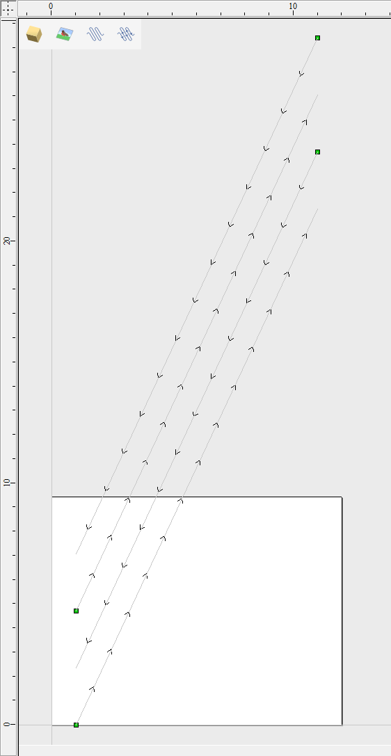
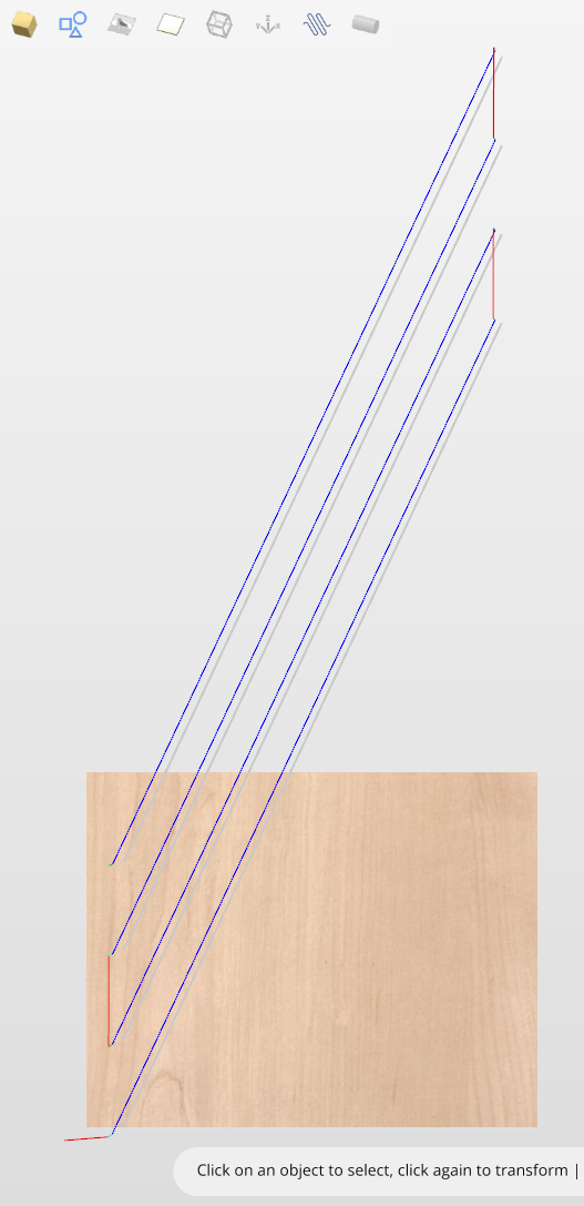
Once the flute vectors are ready, the toolpath can be created again using the Fluting Toolpath. An important thing to note, is the difference between the appearance of spiral toolpaths in the wrapped and flat view. By clicking on Auto Wrapping one can switch from wrapped rotary view to flat view and back again.
As can be seen above, in the flat view the toolpaths will follow the vectors and extend beyond the job boundaries. On the other hand the wrapped view, presented below, will display the toolpaths spiralling around the blank.
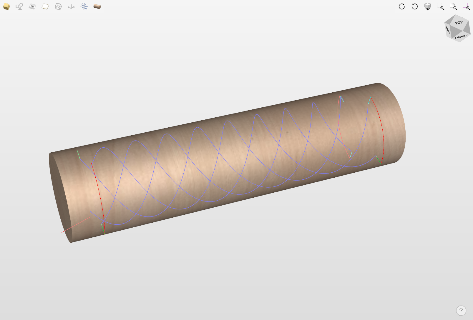
This was just a brief overview of general 2D workflow for rotary machining. Remember to also take a look at video tutorials dedicated to rotary machining, which are accessible from the Tutorial Video Browser link when the application first starts.
Getting Started: Online Machine Configuration
We are providing a selection of prepackaged machine configurations for the most popular machine manufacturers and the list is continually growing.
This will take you to the Search Machine Online dialog. If you find and download your machine, it will be imported into your tool database with some initial feeds and speeds for a set of tools. It will also be associated with the post-processors compatible with it.
This can all be done or edited later on through the Machine Configuration dialog.
Can't find your machine?
If you can't find your machine, you can configure it manually in the next step, or later on through the Machine Configuration Management dialog.
Snapping Options Dialog
To help with drawing, construction and layout, the 2D View has Rulers which are displayed along the top and down the left side of the window. In addition to the Rulers there is the option to use Guidelines and The Smart Cursor to help with construction of vectors or positioning of other objects in the 2D View.
Rulers
The Rulers are permanently displayed in the 2D view to help with positioning, sizing and alignment. The graduated scale automatically uses the units set for the project and zooming in / out shows the sizes in 10ths.
Guidelines
Guide Lines are used to help layout designs and make it very easy to sketch shapes by clicking on the intersections of Guides. Guide Lines are easily be added to the 2D view by pressing the left mouse button down on the appropriate ruler (left if you want a vertical guide and top if you want a horizontal guide) then holding the button down and dragging the mouse into the 2D view.
While dragging a Guide into position it automatically Snaps to the units displayed on the ruler. This snapping behavior can be overridden by holding down a Shift key while dragging the guide. After positioning a Guide it can easily be moved to a new position by clicking the right mouse button on the guide to open the Guide Properties form as shown later in this section. If you hover the mouse over a Guideline then its current position is displayed next to the cursor
Additional guide lines can be added relative to an existing guide line by interactively placing the cursor over an existing guide (the cursor changes to 2 horizontal arrows), Holding a Ctrl key and dragging to the required position. The incremental distance between the guide lines is displayed next to the cursor. Releasing a Ctrl key changes to display the absolute distance from the material origin.
Guides can also be added and other edits made by right clicking on the Guideline which will bring up the Guide Properties form:
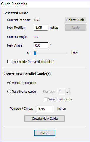
The exact position can be specified by entering a New Position.
Guides can be given an angle by either entering an angle into the New Angle box or dragging the slider and clicking . Angles are measured in degrees counterclockwise from the x-axis. From an angled guide you can only create relative parallel guides.
Guide lines can be locked in position to stop them from being inadvertently moved by ticking the Lock Guide option.
Additional Guide Lines can be added that are positioned using absolute or incremental coordinates. Enter the Absolute or relative positions and Click .
Guides can quickly be toggled visible / invisible by clicking in the Top Left Corner of the 2D view:
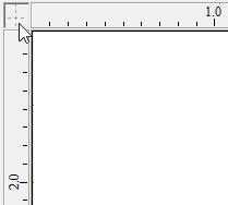
Alternatively the visibility can be changed using View Menu ► Guide Lines from the Main MenuView Menu ► Guide Lines ► Delete All Guides from the Main Menu
Snapping Options
These options can be used to help create and edit vector geometry.
The Snapping Options form can be accessed by selecting Edit ► Snap Options from the Main MenuF4.
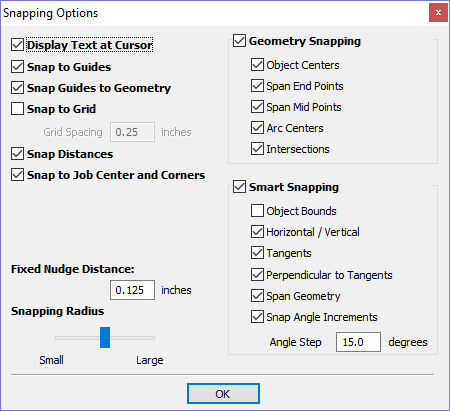
Display Text at Cursor
Displays the XY coordinates on the cursor making it easy to see the position for each point
Snap to Guides
When this option is checked ✓ drawing and positioning vectors will snap onto any horizontal or vertical guide lines visible in the 2D view.
Snap Guides to Geometry
When checked, ✓ the Guide Lines can snap to Geometry while being dragged.
Snap to Grid
Displays a grid of points separated by the Grid Spacing which can be snapped to when drawing or editing vectors and other objects in the 2D View.
Snap Distances
Snap to fixed lengths based on your zoom level. This occurs when creating shapes, dragging nodes or vectors.
Snap to Job Center and Corners
Snap to the job corners and center. This, also, control the job smart snapping
Fixed Nudge Distances
Objects can be moved small, fixed distances (nudged) by holding Ctrl + Shift and tapping the arrow keys. The Fixed Nudge Distance specifies the distance to move selected objects with each nudge.
Snapping Radius
The snap radius (pixels) will adjust how close the cursor must get to vector geometry in order to snap it. If you work quickly and grab and throw geometry at speed, you may prefer a larger Snapping Radius to pick up geometry that is vaguely near the mouse. If you work precisely or have complex overlapping geometry, you may prefer a smaller Snapping Radius to avoid having to zoom in to select one geometry in an area that has many nearby vectors.
Geometry Snapping
Used to control the position at which the cursor will snap when drawing and moving objects. When drawing, the cursor will snap to items on vector geometry depending what options you have selected in the form under this section.
Object centers, Span End points, Span Mid-points, Arc centers, intersections Horizontally, Vertically and the specified Angle and Distance Guide lines and the intersection of Guides
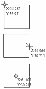
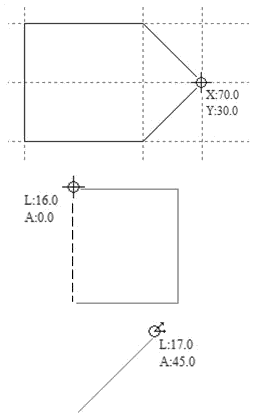
Smart Snapping
Smart snapping works by snapping the cursor to imaginary lines related to vectors and/or nodes. These lines will appear as dashed, and sometimes coloured, lines that go through the vector or node and the cursor point. You can snap to the intersection of those lines by hovering over the nodes that you're interested in. This reduces the need to create construction geometry (for example, for aligning nodes or vectors), and can be used in almost all the shape creation tools, node editing and transforming vectors.
Note
A node is the start, middle, or end point of a span.
Note
The snapping system is watching to see which vectors you hover the mouse over. It remembers that last few vectors as the ones you want to work with and draws the snap lines for those as a priority. There is a maximum number of nodes and vectors that can be "woken up" at the same time to avoid too many snap lines appearing at once.
Snapping lines can be drawn from:
- Nodes that were woken up by hovering the mouse over them or their span
- Vector properties, such as their bounding box or center point
- Material properties, such as extensions from the edge and the middle
Note
It is possible to wake up vectors on the other side of a double-sided job.
Cursor | Type | Description |
|---|---|---|
 | Object Bounds | The theoretical bounding box surrounding the active vector |
  | Horizontal and Vertical Lines | Horizontal and vertical lines passing through a node or a span midpoint. |
| Tangents | Tangents originating from a node or a span midpoint. |
| Perpendicular to Tangents | Lines which are perpendicular to tangents from nodes or span midpoints. |
 | Connecting Lines | Lines connecting two nodes. Includes mid-point. |
 | Span Geometry | Snap to the geometry of the vector. |
 | Angular Constraints | Snapping to specific angles, as defined in the snap options F4. |
  | Job | Horizontal and vertical lines through the center of the job. |
Object Bounds
These snap lines appear on the bounding box edges of the vector, and in the middle horizontally and vertically.
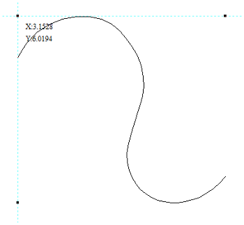
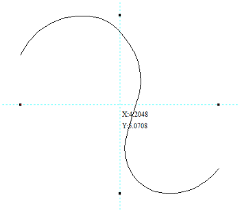
Vertical and Horizontal Lines
Nodes
The snap lines appear when the cursor is near the horizontal or vertical line passing through the woken nodes.
Vectors
Snap lines become available while moving vectors so that it is used for aligning them with other vectors.
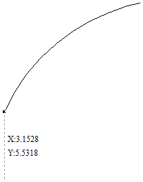
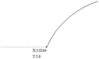
Tangents
These snap lines originate from the woken node and will appear as an extension along the end of the belonging span.
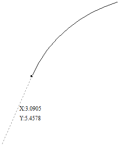
Perpendicular to Tangents
These snap lines will be 90° from the tangent snap line.
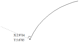
Connecting Lines
If you wake two or more nodes, you could snap to the line connecting them. You could, also, snap to the mid-point of that line.
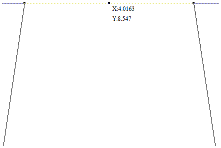
Span Geometry
This allows you to snap to the geometry of the vectors.
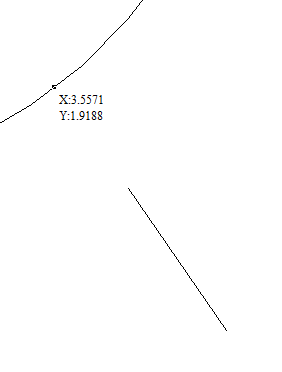
Angular Constraints
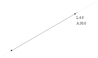
Job Edges & Centre
If you have the job snapping enabled, you could snap to the horizontal and vertical middle lines. This also includes the lines extending from the job's edges.
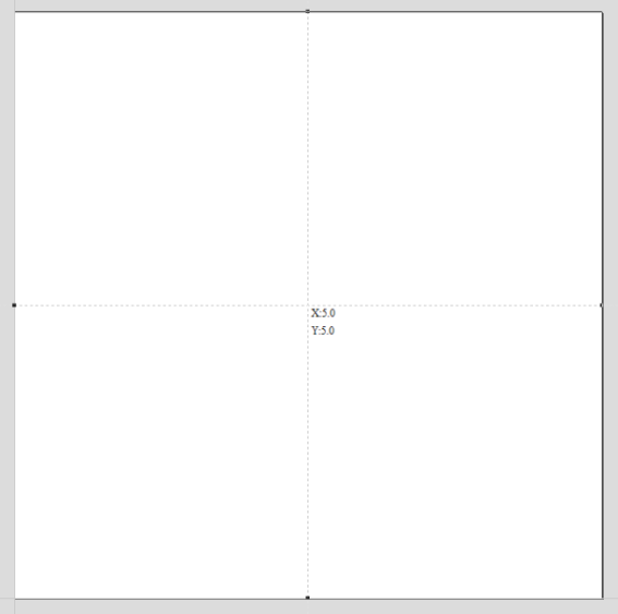
End point alignment
The start and end points can be aligned horizontally or vertically while the vector is being rotated.
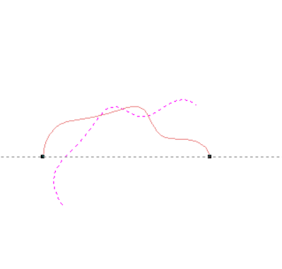
Toolbar Snapping Options
Geometry Snapping, Smart Snapping and Grid Snapping can be switched on and off from the View Toolbar
Any change to the snap settings F4, through the Main Menu or the toggles on View Toolbar will be remembered for subsequent sessions.
Disable snapping temporarily
Snapping can be temporarily disabled by holding down the Shift key.
03. Getting Started - The CNC Workflow
The Vectric Workflow
The Example Project will step you through all the stages of creating, toolpathing and cutting a simple line drawing. Most CNC projects share many common concepts and steps so before we complete our practical project, let's run through them.
The structure of a Vectric Job
All the information needed to describe a single CNC project is contained in a Vectric Job document (when saved they have the file suffixes *.crv or *.crv3d). A new job always begins by defining the area of a sheet of physical material that you intend to cut with your CNC machine.
Most jobs typically only involve one sheet of material, but more complicated projects may comprise multiple materials. Don't worry, your job's primary material sheet can be updated or new sheets of material added to your job later, as your design develops.
The drawings & images used to work on a material sheet can be created on layers to help manage more complicated designs. Similarly 3D model components can also be organised onto levels. By default there is always at least one layer and one level for each sheet in a new job. You can add more layers and levels to help organise more complicated projects.
Once your material sheet has been created in the Job Setup form, the software will show you a 2D & 3D view of your design space (which matches the dimensions of your current material sheet), each in their own window.
Above the view windows is the main toolbar which allows you to navigate through the structure of your CNC job and see what is currently being displayed in view windows below. It shows you the material sheet, design layer and 3D model level that you are currently working on (referred to as 'active').
What you see in the 2D & 3D design views below will reflect these current settings and any new shapes, components or toolpaths will be created in the active locations indicated. You can also change the active sheet, active layer or active level at any time directly from these controls.
More advanced projects can also represent both sides of a sheet of material. For a two-sided project an additional control above the views shows which side of the sheet is currently active. You can view the drawings, models and toolpaths associated with the top and bottom surface of each material sheet and swap the active side of the sheet in a consistent way to the other controls.
Initially your job will be empty and so your views will be blank, but in due course, Vectric's view windows will show all the layered drawings & images, 3D model components & toolpaths for the currently active material sheet.
The currently active locations are the same for both the 2D & 3D views i.e. creating a vector shape will place it on the same active sheet and active layer regardless of whether the 2D or 3D view is used.
You can, however, toggle the visibility of object types in each view independently using the visible items toolbar at the top of each view. This is helpful for focusing on different areas of your job at each stage of creating your CNC project.
Many of the software's tools can be used directly in either the 2D or 3D view.
In V12 some tools have not yet been extended to allow full interaction in the 3D - this is an ongoing transition. If in doubt, try click
Import, Draw or Trace artwork
Computer images are most often represented as a grid of coloured squares - these images are referred to as bitmaps and their constituent coloured squares are called pixels. Except for a few very specific cases, this representation is not *directly* useful for toolpath creation. Computer drawings (from CAD or illustration applications) are very different and are instead built from mathematically defined lines & curves.
This type of representation is referred to as vector or contour artwork. Vectric software can use both bitmap and vector artwork, but most types of toolpath can only be created from vector drawings. Suitable bitmaps with bold regions of similar colour (for example logos, cartoons, icons or signs) can, however, be used to create vectors from which many types of toolpath can then be generated - this process is called bitmap tracing.
Some external artwork file types contain only bitmaps (e.g. BMP, PNG, JPG), some contain only vectors but many can contain both (e.g. PDF, SVG, DWG/DXF).
Use the design artwork to create toolpaths
We use the vector artwork to define the shapes we want to cut. It is important to emphasise that the toolpath (the actual cutting moves your machine must make to leave your intended shape) is rarely, if ever, a direct conversion of the original artwork. The toolpath must be created taking into account a complex interaction of the material, your CNC machine's capabilities and the shape of your cutting tool.
"Sculpture, per se, is the simplest thing in the world. All you have to do is to take a big chunk of marble and a hammer and chisel, make up your mind what you are about to create and chip off all the marble you don’t want." - Paris Gaulois, 1879.
Toolpaths are therefore generated from source vector artwork but once created they are almost entirely indepenendent of the artwork that created them. Moving, editing or even deleting the source artwork used to generate a toolpath will not affect the toolpath - it must be actively re-calculated to reflect any changes.
This is a carefully considered Vectric design principle - although you may be prompted that a significant alteration to your job has occurred - your toolpaths will never change automatically 'behind your back'!
That said, toolpaths do retain a handy reference to the artwork that created them. If you choose to edit a toolpath it will try to locate it's orginal source artwork and re-select it. At this point you can simply recalculate it to reflect any changes you have made to that source artwork, but you can also choose to select additional or entirely different artwork.
Preview
As we've discussed, the actual motion of your CNC machine (the toolpath) required to cut al shape can be complex and difficult to interpret.
Luckily your software provides an extremely accurate preview of any toolpaths that you create by simulating them in a block of virtual material. In the Example Project we will use the Toolpath Preview to verify that the toolpaths are producing the shapes we want (and we can easily corrected them if not)!
This simulated preview is a hugely beneficial step that ensures you minimise costly mistakes in the real world (we all make them from time to time) but it also allows you to check the surface finish you can expect from different strategies under different conditions.
The Toolpath Preview uses exactly the same data that will be sent to your CNC machine. You can be confident that any cutting and surface finish issues that occur at the machine but which are not visible in the Toolpath Preview are almost always caused by a physical problem with the machine setup or tooling, which makes finding and fixing them a lot quicker!
Exporting the toolpath
Now we will be ready to export the toolpath, in the right format, ready to be loaded into our CNC machine's controller. Saving the toolpath will make use of a Post-Processor that is specific to your CNC machine. It will translate the movements contained in the toolpath into a toolpath file that is in the specific format required by your CNC machine's controller to load and run.
Edit
 | Undo | Steps backwards through the last 5 changes made by the user. |
 | Redo | Steps forward through design steps that have been Undone using the Undo command (see above) to get back to stage that the user started using the Undo function. |
 | Cut | Removes the selected objects from the job and places them onto the clipboard. |
 | Copy | Copies selected objects to the clipboard, leaving the original in place |
 | Paste | Pastes the contents of the Clipboard into the model (see cut and copy above). |
| Delete | Deletes the selected object - same as hitting the Delete key on your keyboard |
| Selection► | Select various types of vectors |
| Align Selected Objects ► | Give the user all the options covered under the Align Objects section of the menu. Opens the Alignment Tools form. |
| Join Vectors | Joins open vectors. Opens the Join Vectors form. |
| Curve Fit Vectors | Allows arcs, Bezier curves or lines to be fitted to existing vectors to 'smooth' them. Opens the Fit Curves to Vectors form. |
| Nest Selected Vectors | Opens the Nesting form. |
 | Job Size and Position | Opens the Job Setup form. |
| Swap Sides | Swap between Top and Bottom Sides on a 2 Sided Project. |
| Notes | Opens a text box where you can record notes regarding this job, such as customer name, material required, special setup instructions or any other relevant text information you would like to keep when you save the job. If the text starts with a period/full stop/dot '.' , the Notes dialog will be displayed automatically each time the file is opened. The text from the Notes dialog can also be optionally output into the toolpath as a comment field. See the Post-Processor Editing Guide. |
| Document Variables | Opens the Document Variables dialog. |
| Snap Options | Opens the Snap Options dialog. |
| Options | Opens the Program Options dialog to allow the customization of certain aspects of the program. |
Selection
| Select All Vectors | Selects all the currently visible vectors in the Design (vectors on invisible layers are not selected). |
| Select All Open Vectors | Selects all the currently visible Open vectors in the Design |
| Select All Duplicate Vectors | Selects all the currently visible Duplicate vectors in the part - these are vectors which are exact copies of each other in terms of shape and location so that visually they appear to be only one vector. These can cause problems for some toolpath and modeling functions so it can be useful to delete them or move them to a new layer. |
| Select All Vectors On Current Layer | Selects all the vectors on the selected layer. |
| Unselect All | Deselects all the currently selected vectors in the part |
| Vector Selector... | Opens the Vector Selector dialog. |
Notes
- This allows you to add notes to your file/model.
- If the notes start with . the notes section will auto open when you open the file with which they are associated.
There is also a spell checker features attached to that.
- The software checks the spelling for the user and underlines the misspelled words with red.
- When an underlined word is clicked. It suggest corrections for the user.
- There is an add word feature if you want to add a new word.
- There is a remove word feature if you want to remove a word you added by mistake ( it has to be a word added by the user).
- The language of the spell checker is the same as the language of the software.
- All the Software supported languages are supported by the spell checker except for Japanese
HTML Links.
To enter a link into the Note, go to the appropriate page in your Web Browser and select the URL of the page from the Address Bar.
CRTL+C to copy it and then in the Note Field, right click and use the "Paste" option to enter it into the Notes.
To use the HTML Link in the Note Window, hold the CRTL Key and click the link. This will open your computers default Web Browser and load the web page.
Join / Close Vector with a Straight Line
Join with a Line finds the closest end points on 2 selected, open vectors and joins with a straight line. Close with a Line closes a single open vector with a straight line between its two end points.
Watch this video to see this in action:
Usable In Both Views
This tool can be used in both the 2D and 3D View.
2D View offers a more direct way to view your vectors while 3D Offers more flexability to work with Vectors in 3D Designs and to make use of the Edit Boxes.
Grouping and Ungrouping
Grouping objects allows you to select, move and manipulate them as if they were one entity. The process is entirely reversible by Ungrouping.
See Grouping and UnGrouping.
Edit Toolpath
This option is used to modify an existing toolpath. Click to select a toolpath in the list then click the edit option to open the form.
The vectors associated with each toolpath are automatically remembered, so editing a toolpath will automatically select the vectors in the 2D window.
Make the required changes to the toolpath parameters Click the Calculate button to update the toolpath
A toolpath can also be edited by double-clicking on its name in the toolpath list.
Overlap Vectors
Selected closed vectors that overlap can be merged together to create a new shape. These tools consider the closed vectors to be solid areas.
The following examples begin with these five vector shapes where the rectangle was selected last.
Only areas of the first selected parts (the circles) that are covered by the last selected vector (the rectangle) remain after this operation.
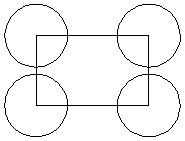
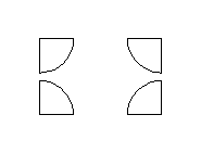
Watch this video to see this in action:
Usable In Both Views
This tool can be used in both the 2D and 3D View.
2D View offers a more direct way to view your vectors while 3D Offers more flexability to work with Vectors in 3D Designs and to make use of the Edit Boxes.
3D Segmenting
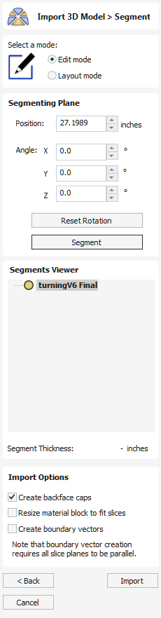
The Segment tool can be used to split a 3D model into separate chunks or segments to allow them to be machined using a 3-axis CNC machine.
To get to the segmenting tool you first have to import a 3D model using the standard Model Import Dialog.
There are 4 main sets of options:
- The mode selection controls which mode we are in.
- The Segmenting Plane section controls the placement of the next segmenting plane. This is mostly for setting exact values. Most of the time, the 3D view controls are more convenient.
- The Segments Viewer gives an overview of the segmenting tree. This shows all of the segments and how they are related to one another.
- The Import Options can be used to control the settings used when we are ready to import the segmented model into the job.
Usage Overview
The segmenting tool works by incrementally splitting the imported model into blocks. The segmenting plane is placed in the model, and we press . Each segmenting operation produces two new segments, one for above the segmenting plane and one for below.
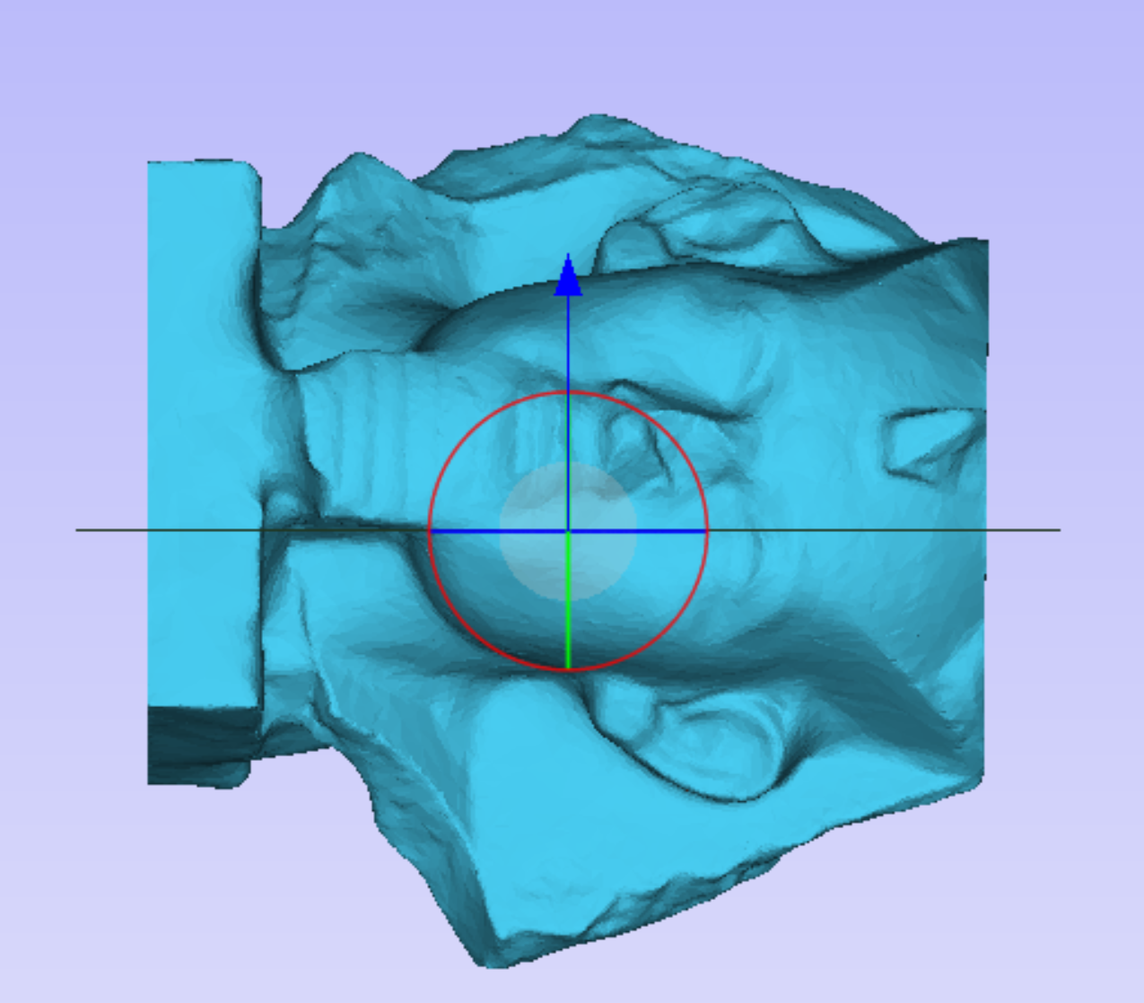
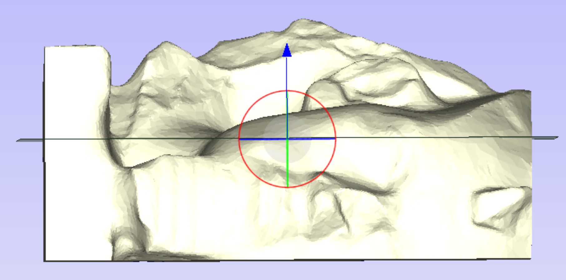
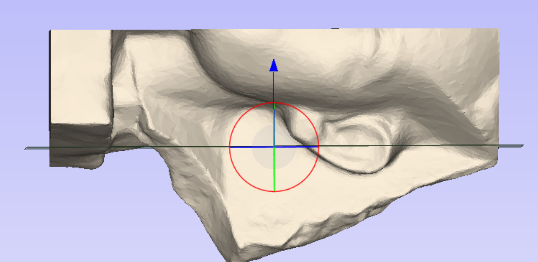
The Segments Viewer shows that this segmenting operation has produced two new segments. Each segment can be selected by clicking in the tree.
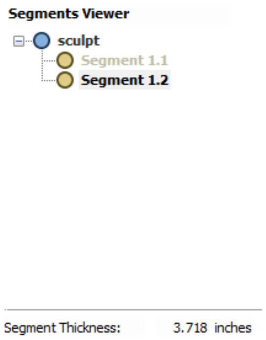
Once a segment has been selected it forms the base for future segmenting operations, and this segment can be further divided, into more segments. The tree reflects the fact that one of original segments has been chosen, and the tree and the parts in the 3D view are coloured to show the result.
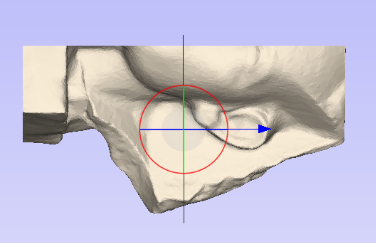
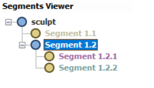
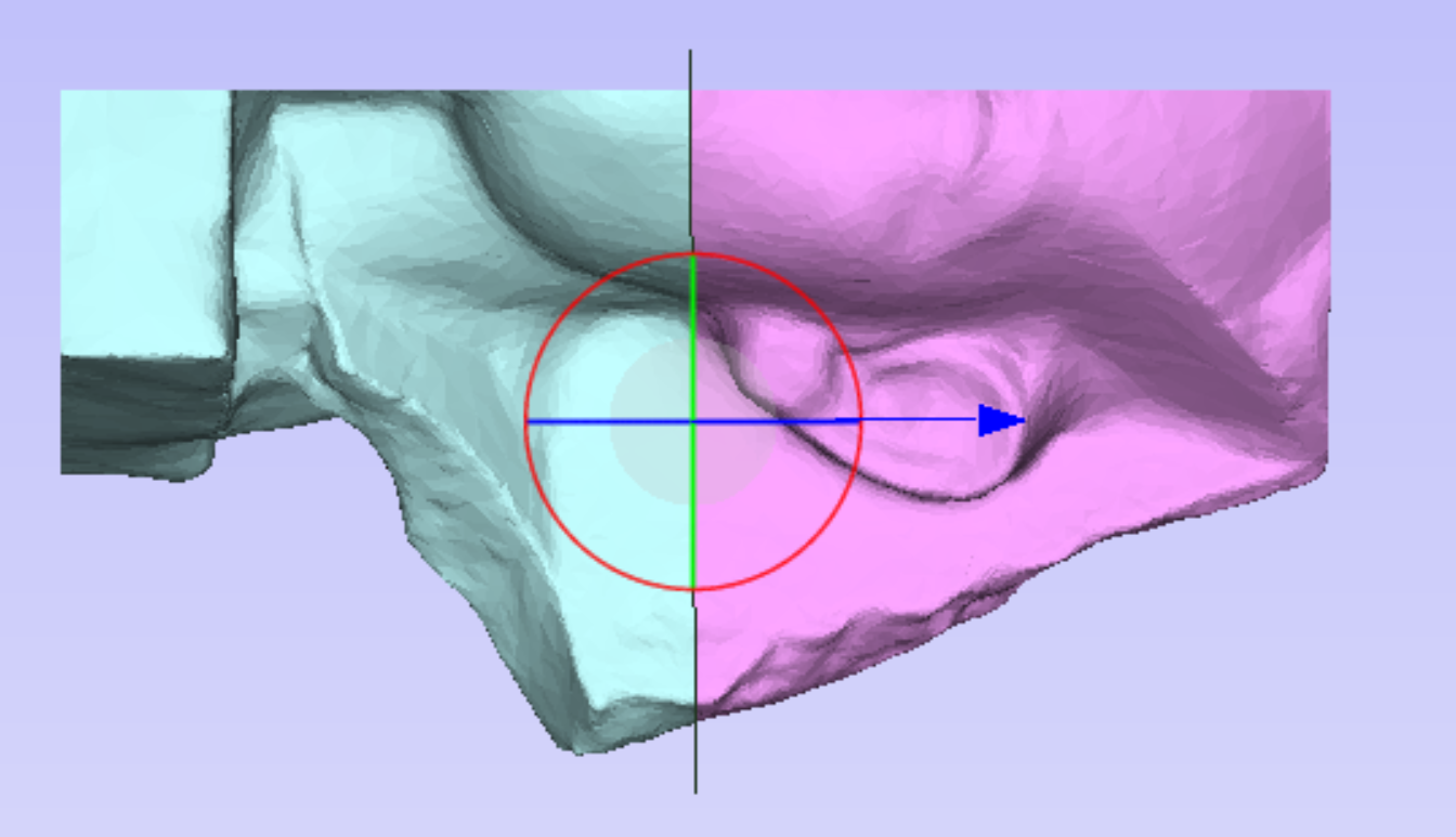
At each step the orientation and position of the segmenting plane can be adjusted to ensure that the resulting segments are appropriate for machining. To adjust the plane you can use one of the dynamic handles shown in the 3D view.
Once the model has been segmented enough then we can enter layout mode. Within layout mode we can see the segments created and how they will look once imported into the job.

At this stage each of the segments can be flipped to a desirable orientation. This is done by selecting a segment and cycling through the different possible orientations using the arrow buttons in the segment positioning section.
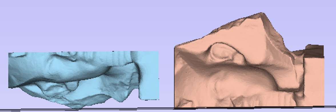
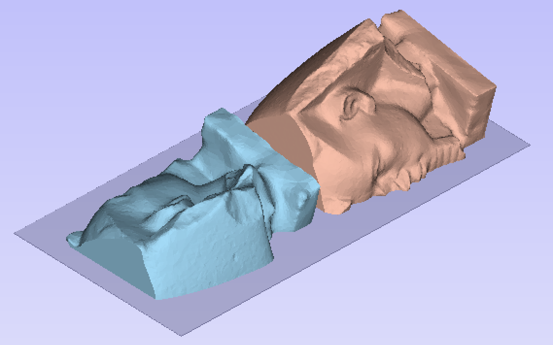
If it is desired to position the segment at an orientation which is not present in the provided cycle-through options, then the segment can be interactively rotated. Select the segment in question and press the shortcut on the keyboard. This will display a dynamic rotation handle centred on the selected segment which can be used to interactively orient it. Once you are happy with the positioning, press the keyboard shortcut once again to hide the rotation handle.
The other key feature of the layout mode is the visualize undercuts option. When this option is checked then undercut areas (which cannot be cut with a regular 3-axis CNC machine and so are ignored on import) are highlighted. If these areas are significant then it may be desirable to return to the edit mode and segment in a different way to remove these undercut areas.
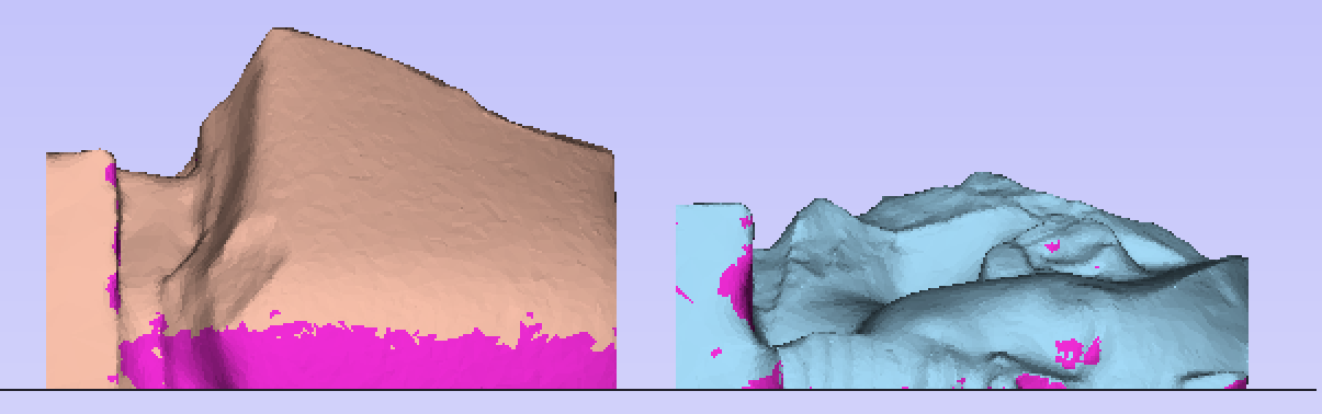
With the dynamic nature of this tool we strongly recommend the viewing of the corresponding video tutorial for a more through coverage of the features
Note
If at any point errors occur with importing or undercut analysis then this might be caused by importing 3D models which have self-intersections. The segmenting tool cannot be used on such models.
Mode Selection
The mode selection switches the tool between layout and edit mode:
- In Edit mode the model can be segmented into different sized segments.
- In Layout mode the segments defined in edit mode can be rearranged, reoriented and visualized.
Segmenting Plane
The segmenting plane section controls the positioning of the next segmenting plane. This plane can be positioned using the 3D view controls, or by adjusting the numerical values in the edit boxes. Once a desired position and orientation have been chosen then pressing the button will produce a new segment.
Segments Viewer
The segments viewer section shows all of the segments in tree view. The root of this tree is the original model. Whenever a segmenting operation occurs then the current segment in the tree gets two children, these two children represent the resulting two segments produced when slicing along the segmenting plane.
At any point any of the segments in the tree can be selected. The 3D view will show only this segment. If this segment has been further segmented then those segments will be displayed visually by having different colours in the 3D view.
Undoing a segment
At any point any segmenting operation can be undone. To undo, select a segment from the tree, right-click and choose Delete children. This will remove the children from the tree and join the corresponding segments back together again.
Note
You can delete the children of any segment, this operation is not restricted to just the most-recently created segments. If at any point you want to restart segmenting altogether you can just delete the children of the top-level node.
Rearranging Segments
You can drag and drop segments on top of one another in the tree to merge two segments together. The resulting segment will just be the result of combining two segments. This can be useful for both recombining or rethinking a segmenting approach. It is also useful if you want to create a segment for a particular part, but that segment includes other parts you don't want.
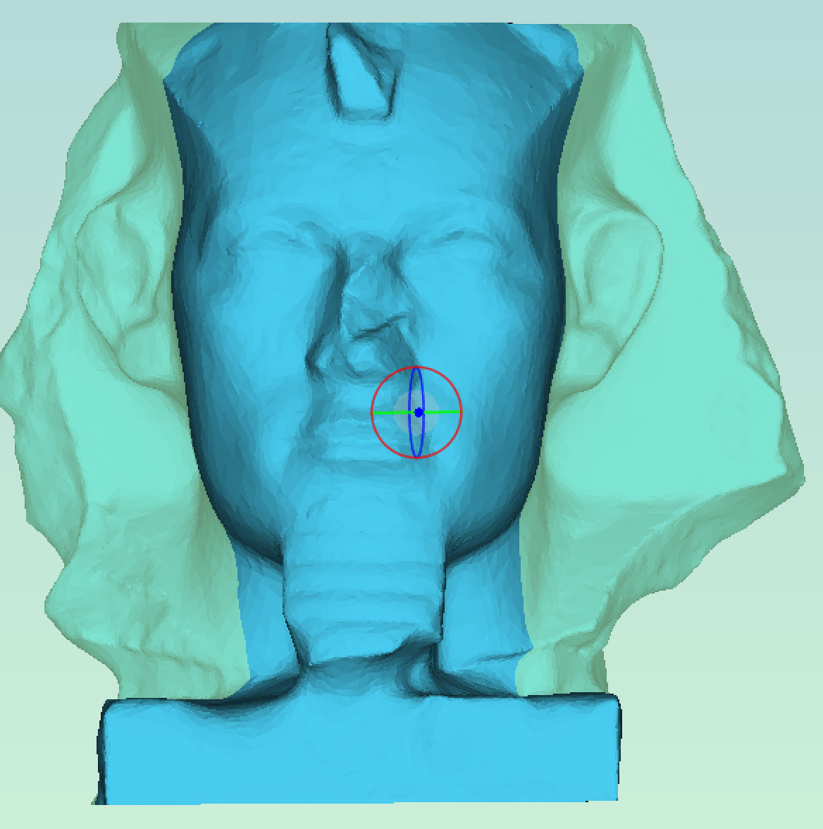
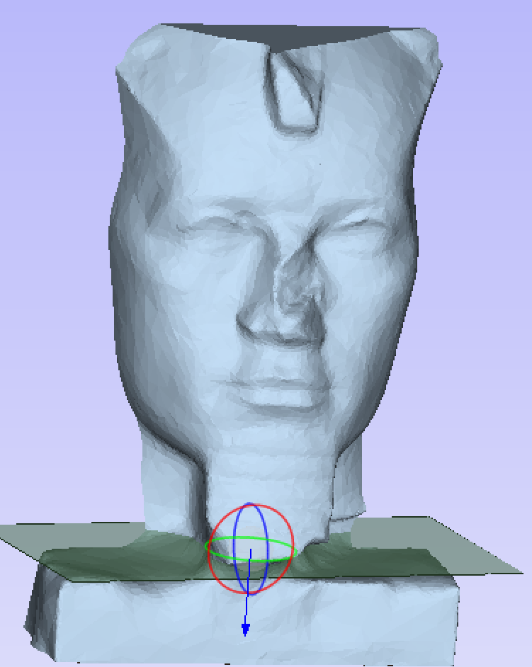
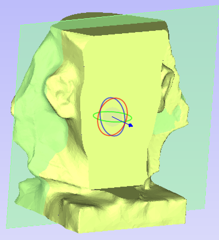
Import Options
Create Backface Caps
If this option is selected then the back of any segment is closed off with a plane. This option may be desireable in mold creation.
Resize Material To Fit Slices
If this option is selected then the job size will be adjusted to accomodate the newly created segments.
Create boundary vectors
If this option is checked boundary vectors are created for the top and bottom boundaries of the segments.
Re-importing a segmented model
Once the segmented model has been imported it may be re-imported by right - clicking any of the imported segments in the component tree and selecting Re-import model. This will return the model to the last known state in the segmenting tool before import.
Component Tree
The model that you see in the 3D View is the result of progressively combining all of the visible components from the bottom of the Component Tree, to the top. The resulting model is known as the Composite Model. The order in which components are combined can have a significant impact on the final shape of the composite model and so you will often need to move components relative to one another within the Component Tree in order to achieve the end result you are intending.
Watch this video to see this in action:
For more information, see the 3D Design and Management page.
Combine Modes
To help you understand how the components are being combined, each component in the tree has an icon indicating how it is currently being combined with the components below


Organization
Component Levels.
Every component exists on a single Level. These levels can be used to organize your modelling process. During the compositing process the contents of a level are combined first before the levels themselves are combined together.
Component Groups.
Grouped components are also indicated by their own icon and the presence of a plus or minus control to the left of the visibility checkbox. These controls allow you expand or collapse the group to show or hide the group contents, respectively.
Selection
Components can be selected in 3 ways:
- By left-clicking on the component's name in the Component Tree
- By left-clicking on the associated grayscale component preview image in the 2D view
- By double left-clicking directly on the component in the 3D view
In all cases, the new selection will subsequently be reflected in all three locations. So, for example, selecting a component in the Component Tree will simultaneously cause the associated 2D component preview to become selected in the 2D View, and the same component to become highlighted in red (or green if the selected component is obscured by another component) in the 3D View.
There are, however, some minor differences between the three methods of selection. Also, depending on the circumstances, there may be some advantages to selecting your components using one method rather than another.
Selection in the Component Tree
The component tree works in a similar way to the Window's file explorer. To select a component, simply click on it. To select multiple components, hold down a Ctrl key while clicking on each component you wish to add to the selection. While in this mode, clicking on a component that is already selected will cause it to be removed from the selection.
Pressing a Shift key allows you to select a range of components. Click on the first component in the range to select it, then holding a Shift key and pressing the last component you want selected will select all the components between the first and last selection.
Double-clicking a component or level in the Component Tree will automatically open the Component Properties tool - see the Component Properties section for more information on how to use this tool to modify the selected components.
Right-clicking an unselected component in the Component Tree will select it, and open its pop-up menu of related commands. Any commands you select will apply to this selected component only.
Right-clicking a component that is already selected, and is also one of several selected components, will open a similar pop-up menu of commands. Any commands you select from this menu will apply to all of the currently selected components.
Selection in the 2D View
The 2D component previews behave exactly the same way as vectors or bitmaps. They can be selected by a single, left-click. Several component previews can also be 'shift selected' (see above). Clicking on selected component previews again activates their interactive transform handles. These can be used to move, rotate or stretch the 2D component preview and its associated 3D component.
Selection in the 3D View
Because the left mouse button is used for twiddling the 3D view itself, a single left-click cannot be used for component selection directly. However, Aspire's 3D view supports most of the standard selection concepts described above, using double-clicks instead. Therefore, to select a component in the 3D view it must be double-clicked with the left mouse button. To select multiple components in the 3D view, hold down a Shift key and double-click each of the components you wish to add to the selection. To access the pop-up menu of commands associated with a component, double right-click it in the 3D View.
Because components may overlap or merge through one another when forming the composite model, you may find that some components become difficult (or are even impossible) to select directly from the 3D view using the double click method. In this case you may use the right click menu. If you right click on a point above the component you wish to select then you are presented with a list of all the components that lie under this point.
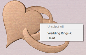
You can also double right-click the selected component (highlighted in red) in the 3D view. The options offered include showing/hiding components, or setting their combine mode within the composite model.
In the 3D view selected object will often be tinted red. On some occasions parts of some components will be obscured by other components. In this case then the red tint will not be seen. The parts of the objects that are obscured will be tinted green so they are still visible from within the 3D view.
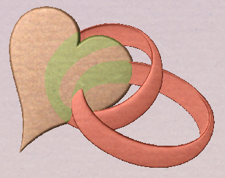
Editing in the 3D View
Many of the dynamic component editing tools can now be accessed directly from the 3D View. Editing the components in the 3D View makes it quick and easy to see the immediate effect of the changes to the Composite Model. To access these editing options a component or components must first be selected. Once selected then either clicking the component again in the 3D view or clicking the Transform Mode icon (Move, Scale, Rotate Selection) will activate the 3D Transform Handles.
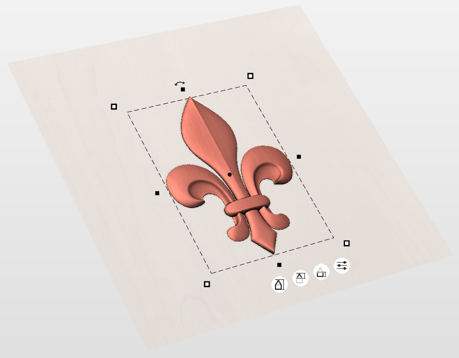
The majority of these will function in the same way that they do with objects in the 2D View.
There are also icons below that can be selected that will allow you to edit the component properties in the 3D view.


When selecting the additional settings option here you can adjust the Combine mode, Fade, Tilt and Appearance. When using the Fade and Tilt options in the 3D view you will need to set the direction of this in the 3D View instead.
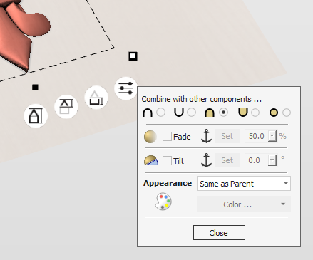
Position in the Component Tree
The position of the component in the Component Tree may affect the resulting combined model. This position can be altered by selecting one or more component(s) and clicking one of the buttons with a blue arrow at the top of the Component Tree. Alternatively, component(s) can be selected and dragged in component tree via mouse. If Ctrl is held when component is being dragged, then the component itself will not be moved, but it will be copied instead and placed at the desired location.
Group Selected Objects
Vectors can be Grouped allowing any number of vectors to be included as a single object that can easily be selected, moved and scaled etc. The Shortcut key for this operation is G.
Grouping vectors is particularly useful for machining purposes, where different vectors will be used for a single toolpath operation. Clicking any member of the group will select the entire group.
Watch this video to see this in action:
Usable In Both Views
This tool can be used in both the 2D and 3D View.
2D View offers a more direct way to view your vectors while 3D Offers more flexability to work with Vectors in 3D Designs and to make use of the Edit Boxes.
Draw Ellipse
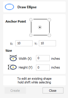
Ellipse / ovals can be created interactively with the cursor and Quick Keys or by entering the exact coordinates for the center point, height and width with typed input.
Watch this video to see this in action:
Interactive - Cursor
The quickest and simplest way to draw an ellipse is:
- Click and drag the left mouse button in the 2D View to begin drawing the ellipse from its corner.
- While holding the left mouse button, drag to the required size.
- Releasing the left mouse button.
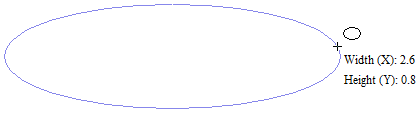
- Holding Alt and dragging creates an ellipse from the middle point.
- Holding Ctrl and dragging creates a circle.
Quick Keys
Instead of releasing the left mouse button when you have dragged your shape to the required size, you can also type exact values during the dragging process and set properties precisely.
- Left-click and drag out your shape in the 2D View.
- With the left mouse button still pressed, enter a quick key sequence detailed below.
- Release the left mouse button.
Default
By default, two values separated by a comma, will be used to set width and height of your ellipse. One value will create a circle with the given diameter. While you are dragging out the ellipse, type Width Value , Height Value Enter or Diameter , Enter to create an ellipse with the specified dimensions.
Specifying Further Properties
By using specific letter keys after your value, you can also indicate precisely which property it relates to.
- Value X - Creates an ellipse at current dragged height but with set width
- Value Y - Creates and ellipse at current dragged width but set height
- Value W Value H - Creates an ellipse with set width and height
Examples
- 1 x Current dragged height with width (X) of 1
- 1 y Current dragged width and height (Y) of 1.
Exact Size
Accurate ellipses can also be drawn by entering the required XY origin point with the Width and Height of the oval. Click to create the ellipse.
Editing an Ellipse
To edit an existing ellipse:
- Select the ellipse to modify and open the Draw Ellipse form.
- The selected shape is displayed as a dotted magenta line.
- Edit the Width and Height values.
- Click to update the ellipse.
To modify another ellipse without closing the form hold a Shift key down and select the next ellipse.
Usable In Both Views
This tool can be used in both the 2D and 3D View.
2D View offers a more direct way to view your vectors while 3D Offers more flexability to work with Vectors in 3D Designs and to make use of the Edit Boxes.
VCarve Inlay Toolpath
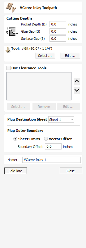
VCarve Inlay toolpaths allow easy generation of the Pocket and Plug toolpaths to cut out your design in 2 Parts ready for creating a VCarve Inlay piece.
Once the toolpaths are generated, they will create 2 seperate toolpath sets, one for the Plug and another for the Inlay itself.
Both of these have their own slightly different Tool forms when editing them after an initial Calculation.
Separate Toolpaths
After the original Calculation of your VCarve Inlay toolpaths, for the Inlay and Plug parts, they are no longer linked. If you Edit one of these, you need to ensure you make any suitable adjustments to the other sides toolpaths to match your changes. If you are unsure about this, consider deleting both parts of the Inlay toolpath and return to the original form to create a new set of VCarve Inlay toolpaths which take your desired adjustment into account from the beginning.
VCarve Inlay Toolpath - Pocket
Changing VBit
Both Pocket and Plug must use the same VBit to fit together correctly. If you need to change the VBit used in an VCarve Inlay toolpath, delete the Pocket and Plug toolpaths and regenerate a new VCarve Inlay toolpath with the appropriate new tools.
Watch this video to see this in action:
Cutting Depths
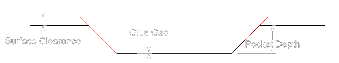
Pocket Depth
This is the Maximum Depth your Pocket will be cut down to, but may not reach this depth depending on the vector design and the angle of the VBit used.
Glue Gap
This is the distance between the Top of the Plug and the Bottom of the Pocket when the 2 halves are placed together.
This value should be greater than 0 and less than the Pocket Depth.
0.001"~0.01" or 0.02~0.2mm are common values to use but can vary depending on your project.
Surface Clearance
This impacts the gap between the lowest point of the Plug and the highest point of the Pocket Material piece.
The Higher the Gap value the less material is left on the Plug to remove later.
The Smaller the Gap value, the closer the two material pieces will be and the more sturdy the Plug Piece will be.
A value larger the 0.0 and lower then the material thickness must be used.
Tool
Clicking the button opens the Tool Database from which the required VBit Tool can be selected. See the section on the Tool Database for more information on this.
Clicking the button opens the Edit Tool form which allows the cutting parameters for the selected tool to be modified, without changing the master information in the database.
Use Clearance Tools
Check ✓ this option if you wish to use End Mill, Ball Nose or Engraving cutters to machine the large open regions of a design. If no tool is selected here but Flat Depth is specified then the selected V-Bit tool will be used to clear the flat areas as well as for the V-Inlay. All the tools in this section will leave an allowance for the V-Bit tool. Subject to this, the first tool in the list will remove as much material as it can, whereas subsequent tools will only machine areas the previous tools could not fit. The order of the tools in the list should match the order they will be run on the machine.
Clicking the button opens the Tool Database from which the required clearance tool can be selected and added to the list.
Clicking the button will remove the selected tool from the list.
Clicking the button opens the Edit Tool form which allows the cutting parameters for the selected tool to be modified, without changing the master information in the database.
Clicking the up and down arrow buttons will move the selected tool up and down the list respectively.
Plug Destination Sheet
This allows you to select the Sheet the Plugs Vectors and toolpaths will be placed on.
If the same sheet as the original vector is selected then the Vectors and toolpaths will be placed mirrored from the original vectors position.
If a different sheet is selected then the new vectors and toolpaths will be mirrored and moved to the center of the new sheet.
If the final position of the new generated vectors needs to be adjusted, move the vectors as normal and recalculate all toolpaths to update the toolpaths to match.
Plug Outer Boundary
Sheet Limits
This will create a toolpath to cut from the edge of the design to the sheet edge.
Vector Offset
With the Vector Offset option selected the Plug will only cut the area around the vector, which can help reduce the amount of material that needs to be cut, but this might require additional processing to remove the Plug from the surrounding material before it can fit into the Pocket part.
Boundary Offset
Increasing the Boundary Offset will increase the material removed around the Plug.
Negative values will be ignored, you will only be able to use a positive values in this field.
Name
The name of the toolpath can be entered or the default name can be used.
Object Selection Tools
Once vectors have been created within Aspire or have been imported from other design software packages you may want to make changes to them. These changes may be to prepare for machining or for use as construction vectors for making 3D shapes using the Modeling Tools. There are a number of functions for editing vectors which will be covered in this section of the manual. All the icons under the Edit Vectors section of the Drawing Tab will be referenced along with the icons under the Align Objects section of the menu.
Editing Modes
From the 2D view a vector can be selected and then three different editing modes allow different dynamic edits to be made to the vector(s) depending on which option is selected from the Edit Vectors section.
The three editing modes are:
By default the software is normally in the Vector Selection mode.
Create Rounding Toolpath
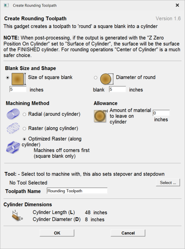
This gadget is used to simplify the task of creating toolpaths to machine a rough blank to a finished diameter for users with a rotary axis / indexer. It supports rounding from either round or square stock and creates the toolpaths directly from the gadget. The gadget is designed to be used in a rotary job
As with all Vectric gadgets, the first part of the form gives an overview of the gadgets purpose.
The start of the form also makes a VERY important point about where the Z origin should be set when the toolpaths are output via a wrapping post-processor. This has to be configured during job setup.
You have the choice of specifying if the tool is being zeroed on the center of the cylinder or the surface. When you are rounding a blank, you cannot set the Z on the surface of the cylinder, as the surface it is referring to is the surface of the finished blank. We would strongly recommend for consistency and accuracy that you always choose 'Center of Cylinder' when outputting wrapped toolpaths as this should always remain constant irrespective of irregularities in the diameter of the piece you are machining or errors in getting your blank centered in your chuck.
A useful tip for doing this, is to accurately measure the distance between the center of your chuck and a convenient point such as the top of the chuck or part of your rotary axis mounting bracket. Write down this z-offset somewhere, and zero future tools at this point and enter your z-offset to get the position of the rotary axis center
The Create Rounding Toolpath form is divided into 4 logical sections.
Blank Size and Shape
The gadget supports creating a toolpath to machine either a square blank or a round one. In this section you specify the shape of your initial blank and its dimensions. The diagrams show which dimensions are being specified.
Machining Method
The gadget offers a choice of three types of machining and for all types you can enter an allowance that will be left on the final shape if required. The Radial and Raster options can be used with either square or round blanks, the Optimized Raster can only be used for square blanks.
Radial (around cylinder)
This option creates a toolpath which rotates the blank around its axis 360° before stepping over to the next pass by the tool stepover distance and rotating the blank back again.
Raster (along cylinder)
This option machines along the length of the cylinder before incrementing the rotary axis round by an amount equal to the tool stepover and then returning the tool back along the cylinder axis. For many machines where the rotary axis is often slower than the X or Y axis, this strategy may allow shorter machining times.
Optimized Raster (along cylinder)
If you are machining a square blank into a round shape, the previous options generate a large number of wasted toolpath moves, because for much of the machining process they are machining 'fresh air'. The 'Optimized Raster' strategy only creates the toolpaths where there is actually material on the blank and hence is much more efficient for square stock.
After choosing your machining method, the next section on the form allows you to pick the tool you will be machining with. The tool is selected from the standard Vectric tool database and will control the stepover, step down and feed rates for the toolpath. It is important to note that after choosing the tool you will not be able to edit the parameters, so you must set up the tool with the correct parameters in the tool database to begin with. This section also allows you to specify a name for the toolpath which will be created.
The values in the final section of the form are picked up automatically and are presented for reference only.
After filling in all the values (all values will be remembered as the default values to use the next time the gadget is run), press the OK button and the toolpath will be generated within the program.
Crop Bitmap
Select the image you would like to crop. Then using shift + left click select the closed vectors you would like to use to crop the image. You may select multiple vectors but the image must be selected first. Click the crop bitmap button to clear the image outside of the vector. If multiple vectors are used for the cropping then the crop tool leaves only the area of the image that lies inside the selected contours.

04. Getting Started - One-Time Setup
One-time setup
Before we can begin, however, we must complete a couple of one-time steps to ensure your newly installed software is correctly configured. We will start by showing you how to log in to Vectric's online portal, V&Co. Here you will be able to download many other tutorials & projects, clipart packs and software updates. It is also the place you will find your personal product license code and you can return to it any time should you need to recover this licence information or use the main product installer again for any reason in the future. We will also use V&Co to access our online Machine Database. We can use this to automatically configure your software for the make and model of your CNC machine. Licensing and configuring your software typically only needs to be completed once and if you are online they can both be completed almost entirely automatically with just a few clicks.
Licence Management & Your V&Co Account
It is important that your investment in our high quality CNC software is protected and that Vectric can continue to create great software in the future - you will, therefore, have a unique personal licence for the software that you have purchased.
This licence is associated with your Vectric V&Co account, and can be accessed at anytime via https://portal.vectric.com. To log in to your V&Co account you will need to use the email address (which must be uniquely yours) and password that you registered with us when your account was created - please keep these details safe. Your registered email address is the way by which we can verify your ownership of the software.
Important Note: you can reset your password at any time using your registered email account and the forgotten password link provided on the V&Co log in page. If you need to change your registered email address it is important to do this before you lose access to the one to which the software is registered. If you can no longer access your registered email, you will need to contact us directly at support@vectric.com but please note that you will now need to be able to provide independent and alternative proof of your identity and purchase.
Within your V&Co account there is a unique digital code for each piece of Vectric software you have purchased. When you first run our software on your laptop or PC you will be prompted to provide this information. If you are installing onto a computer that is online (i.e. with unrestricted internet access available) you can complete this process almost entirely automatically - this is the fastest and easiest method.
The software will simply launch your web browser and prompt you to log in to your portal account. The software will then show the appropriate license that is available to be linked. Simply accept the link and you're good to go!
Once you have completed this process after initial install you will not be required to do it again unless you change computers or need to re-install the software afresh. Your software is now uniquely licenced to you and your details will always be shown in the main interface - even when you are offline, or online but not logged-in.
You can also log into your V&Co account from within the software at any time when you are connected to the internet to enable additional online features and services such as your clipart collection or online tool database.
When logged-in, your software will indicate this in the top right corner of the main window. Please note, the one-time licensing of your software and routinely logging in when using your software are independent concepts. Your personal product licensing is unaffected by your V&Co logged-in status.
We have also ensured that you can complete the software licensing process without having a live internet connection. The process is less automatic and details of the steps can be found here.
CNC Machine Tool Configuration
The software supports hundreds of different types of CNC machine, so the the next thing we will need to do is configure the software for your particular make and model. Correct configuration comprises two elements - appropriate tool settings in the tool database for your CNC machine and setting the 'translation' file (the Post-Processor) needed to create a toolpath file that your specific machine tool controller can understand.
Tool Database
Configuring the software will create a default tool database with tool definitions include cutter movement speeds ("feedrates") that *should* be a reasonable starting point for you to edit the entries for the tool types that you have, according to the recommendations from your CNC machine manufacturer for each material. Appropriate tool settings are the result of a complex interaction of the tool's shape and design, the nature of the material you intend to cut and the strength and power of your CNC machine. Don't use any default settings without first considering whether they are appropriate for your circumstances.
We will look at the Tool Database in more detail in the Toolpath Creation section below.
Post Processors
Your software can create toolpath files for hundreds of different CNC machines and controllers. To achieve this, the software creates an internal representation of a toolpath. Only when this toolpath is saved does it get 'translated' into the specific format required by your CNC machine.
The translation instructions are contained in file called a Post-Processor (because it *processes* the toolpath *after* it has been created).
Post-Processors also determing whether the toolpath movements will be presented to the machine using metric or imperial units. This must typically match the units mode you have set on your CNC machine's controller (seek advice from the manufacturer if needed). Note, however, it doesn't matter what units where used to create the original toolpath within the software - any required conversion is automatically applied when the toolpath is saved through the Post-Processor.
Job Setup - Axis Orientation
Our software is specifically designed for 3-axis CNC Machines (with additional support for an optional rotary axis). As you look at your CNC machine, the normal conventional is that left and right movement is controlled by the X-axis, forward and backward movement controlled by the Y-axis and up and down movement is controlled by the Z-axis.
In our software the width of your job will typically be equivalent to the X-axis of your CNC machine and the height of your job to its Y-axis.
Be aware that some machines are orientated so that the X & Y axes are swapped as you look at them - left to right movement may be controlled by the Y-axis and vice versa.
Use your machine's control software to jog your machine independently in each axis to make sure your expectations are correct.
Although unusual, it is possible that some post-processors will swap the X & Y toolpath coordinates after you have created your toolpaths - effectively changing the apparent orientation of you job - but this is only recommended for users who are confident of their machine's configuration and usage and not recommended for the majority of users who might not be aware of the other issues this can cause. Check with your machine tool manufacturer if you have any doubts.
It can help Orientate yourself so that when you stand before the machine, when you jog the machine to move to a higher X position, it is moving Left to Right infront of you. This can help visualise how the project design you have made in the software will translate to the bed of your machine.
Document Variables
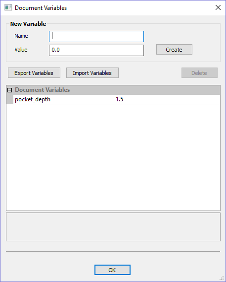
Document Variables provide a mechanism for defining values that can be used in Aspire's Document Variables. They can either be created in the Document Variables dialog which is accessible under the Edit menu, or created from any Calculation Edit Box which supports variables by right clicking and selecting Insert New Document Variable from the Popup Menu.
Naming Document Variables
New Document Variable names must begin with a letter and then may consist of letter, number and underscore characters. Once created, they may be edited in the table beneath the New Variable section of the Document Variables Dialog.
Variables can be exported to a text file and imported into another job. When importing, any existing variable values with the same name will be replaced.
Deleting Document Variables
Variables may be deleted if they're not being used in any toolpath calculations but only when there are no toolpath creation forms open.
Using Document Variables
Once created a Document Variable may be used in any Calculation Edit Box by enclosing its name within a pair of curly braces as illustrated in the figure below.
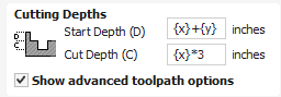
Right clicking in a Calculation Edit Box provides a Popup Menu that provides shortcuts for creating new Variables and inserting existing variables into the Edit Box.
Once a Document Variable has been created from the Popup Menu it will be inserted into the Edit Box.
Accessing Document Variables
Declared Document Variables can be easily accessed from a calculation edit box. Right-click on the calculation edit box and you will be presented with a menu showing the document variables available currently, as well as an option to quickly insert a new document variable.
Set Size
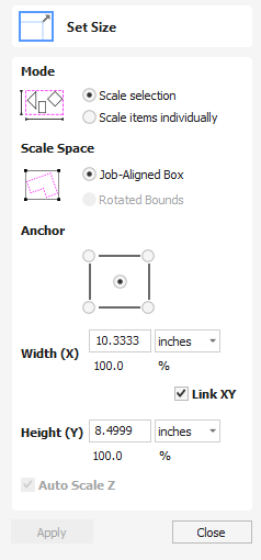
Selected items in the 2D View can be accurately scaled or resized using this option.
Watch this video to see this in action:
Mode
There are two choice of scaling mode:
- Scale selection
- Scale items individually
If scale selection is chosen then the whole selection is scaled as if it were a single group. If scale items individually is chosen then the scaling is applied to each of them as they were all selected one by one.
Anchor
The anchor position determines the point on your selected object's bounding box that will be resized to the dimensions entered.
Link XY
Checking ✓ this option will always scale the height and width in proportion. Leaving the Link option unchecked allows non-proportional scaling
Auto Scale Z
This option sets a specific mode of scaling for 3D Components. When it's checked, ✓ scaling a model component in X or Y will result in it also scaling proportionately in Z, as such if you increase its size in X and/or Y then its Z Height will also increase and conversely when you reduce its X and/or Y size it will shrink in height. When it is unchecked then the Z Height of your Components will remain constant regardless of any X and/or Y scaling done either within this form or dynamically using the mouse in the 2D or 3D View.
Interactive Sizing
The default mode is to enable selected items to be scaled interactively by clicking twice with the mouse.
The process is:
- Select the vectors
- Click a second time to activate the interactive options - handles on the selection box
- Click and drag on the white handles
The keyboard shortcut T opens the Scale form in interactive mode
Usable In Both Views
This tool can be used in both the 2D and 3D View.
2D View offers a more direct way to view your vectors while 3D Offers more flexability to work with Vectors in 3D Designs and to make use of the Edit Boxes.
Scale Model Height
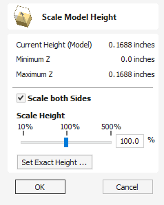
This tool applies a global scaling to your final composite model. This allows you to accurately fit a design within the available material or to manage the depth of cuts required, without having to individually adjust the depth of each of the contributing Components.
Scale Both Sides
This option can only be selected when working within a 2 Sided Setup. Checking ✓ this option enables you to scale both sides of the model. If this is unchecked then you are only scaling the model of the side you are currently working on.
Scale Height
This slider will allow the user to increase and decrease the height of the model as a percentage based on its original height (when the Scale tool was selected).
Set Exact Height...
Clicking button lets the user define a specific value (in the current working units) for the height of the model, rather than use the proportional slider. If you are working in a two sided environment you have the option scale both sides. Checking ✓ this option enables you to scale both sides of the model. If this is unchecked then you are only scaling the model of the side you are currently working on.
Apply/OK
Exits the dialog keeping the changes made to the Model.
Close/Cancel
Exits the dialog discarding the changes made to the Model.
01. Interface Overview
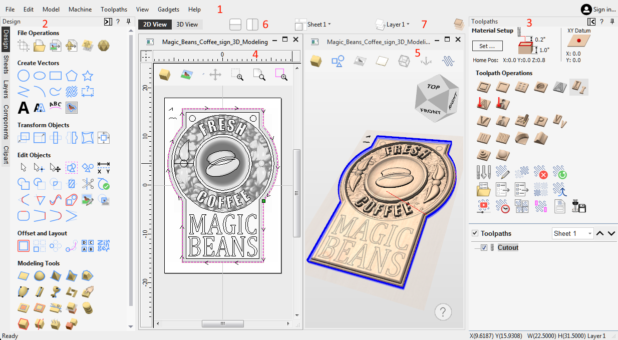
- The Main Menu Bar (the Drop Down Menus) along the top of the screen (File, Edit, Model, Machine, Toolpaths, View, Gadgets, Help) provides access to most of the commands available in the software, grouped by function. Click on any of the choices to show a Drop-Down list of the available commands.
- The Design Panel is on the left side of the screen. This is where the design tabs can be accessed and the icons within the tabs to create a design.
- The Toolpath Tab is on the right side of the screen. The Top section of the toolpaths tab houses all of the icons to create, edit and preview toolpaths. The bottom half shows you toolpaths that you have already created.
- The 2D Design window is where the design is drawn, edited and selected ready for machining. Designs can be imported or created directly in the software. This occupies the same area as the 3D View and the display can be toggled between the two using F2 and F3 or the tabs at the top of the window.
- The 3D View is where the composite model, toolpaths and the toolpath preview are displayed, and can also be used to create your Vectors, 3D models and edit them both.
- If you wish to see the 2D and 3D views simultaneously, or you wish to switch your focus to the Toolpaths tab at a later stage of your design process, you can use the interface layout buttons (accessible in the 2D View Control section on the Drawing Tab) to toggle between the different preset interface layouts.
- Quick Drop down menus can be accessed here to change the current Layer, Sheet or Component Level you are working on.
Managing the Interface
The tool pages have Auto-Hide / Show behavior which allows them to automatically close when not being used, thus maximizing your working screen area.
The software includes two default layouts, one for designing and one for machining, which can automatically and conveniently set the appropriate auto-hide behavior for each of the tools pages. Toggle layout buttons on each of the tools pages allow you to switch the interface as your focus naturally shifts from the design stage to the toolpathing stage of your project.
Accessing Auto-hidden tabs
If a tools page is auto-hidden (because it is currently unpinned, see pinning and unpinning tools pages, below), then it will only appear as a tab at the side of your screen. Move your mouse over these tabs to show the page temporarily. Once you have selected a tool from the page, it will automatically hide itself again.
Pinning and unpinning tools pages
The auto-hide behavior of each tools page can be controlled using the push-pin icons at the top right of the title area of each page.


Default layout for Design and Toolpaths
Aspire has two default tool page layouts that are designed to assist the usual workflow of design, followed by toolpath creation.
In all three of the tools tabs there are 'Switch Layout' buttons. In the Drawing and Modeling tabs, these buttons will shift the interface's focus to toolpath tasks by 'pinning-out' the Toolpaths tools tab, and 'unpinning' the Drawing and Modeling tools tabs. In the toolpaths tab, the button reverses the layout - unpinning the toolpaths page, and pinning-out the Drawing and Modeling pages.You can toggle between these two modes using the F11 and F12 shortcut keys.
Help ?
In all forms is a ? Icon which will take you to the appropriate Help Contents page to cover the tool form you are on in detail.
3D View Help Prompts
The Help Prompts will track your current tool or action and offer quick access to relevant Help documentation or tips on the current tool.
Manual Machine Configuration
If you have downloaded a machine configuration and would like to edit it, or you would just like to create a new machine then you can do so from Machine Configuration Dialog.
This will allow you to edit, duplicate, add or remove machines. It will allow you edit the post-processor associations for each configuration.
- Having a machine configuration allows you specifiy different feeds and speeds for your tools in the Tool Database.
- And then it will allow you to easily select a machine to save your toolpaths with later on.
Thread Milling Toolpath
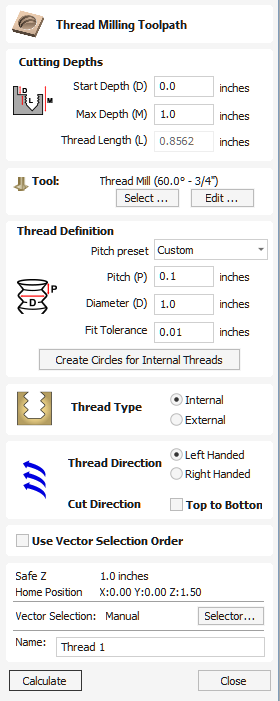
The Thread Milling Toolpath produces:
- internal thread, i.e., something you can screw a threaded bolt into.
- external threads, i.e., the threads for the exterior of a bolt.
It does this by using a special physical tool and a helical toolpath.
To use the toolpath select the vectors you wish to create threaded parts for. The center's of these vectors will be used to define the center of the threaded part.
Set the parameters to match the thread type you require, and then hit calculate to create the toolpath.
Watch this video to see this in action:
Cutting Depths
Start Depth (D)
Start Depth (D) specifies the depth at which the Thread Milling toolpath is calculated from. When cutting directly into the surface of a job the Start Depth will often be Z0. If machining into the bottom of an existing pocket or stepped region, the depth of the pocket/step that you are starting from must be entered here.
Max Depth (M)
Max Depth is the deepest depth below the Start Depth the Threading will cut down to.
Thread Length (L)
The Thread Length is how deep into the thread hole the threads will cut down too. This value will always be less then the Max Depth and is auto calculated from the Max Depth and the Tooth Offset of the Threading tool you are using, and the Pitch of the thread.
Tool Selection
Clicking the Select button opens the Tool Database from which the required Tool can be selected.
Clicking the Edit button opens the Edit Tool form which allows the cutting parameters for the selected tool to be modified, without changing the master information in the database.
The thread milling toolpath supports two types of tool:
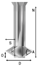
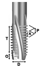
Single Point Tools
When using a single point tool then the created toolpath form a helix. The cutter at the side removes stock material to form the thread.
As seen in the above diagram, a single pointed thread mill tool is assumed to have a triangular cutting face. This triangle is the part of the tool that stands out from the shank of the tool and removes material:
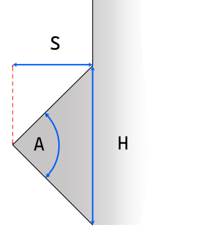
The definition of the tool requires the following fields:
- S - The Tool Size. The horizontal size of the cutting part of the tool
- H - Tool Height. This is the vertical height of the widest part of the cutter face
- D - Tool Diameter. The diameter of the cutter measured from tip to tip.
- A - Tool Angle. The internal angle of the tool
- O - Tool Offset. This is the distance between the bottom of the tool and the tip of the cutter. It must always be bigger than the half of the tool size. Some tools may also have an additional offset, so it may exceed this value.
The Tool Height, Tool Size, and Tool Angle are all related fields. Changing one may change another. For example, if you modify the Tool Height, and the Tool Angle does not change, then the Tool Size must change. This change happens automatically when editing the tools within the tool databse.
Multi Point Tools
It is possible to use a multi-pointed tool for thread milling. A multi-pointed has been designed to cut a single style of thread using a single helical motion. It will cut all the threads in a single go making it more efficient. However unlike single point tools it cannot cut different threads of different pitches.
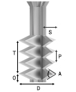
In addition to the dimensions required for the single pointed tool, the multi-point tool also needs to know the threaded length. This is defined as the distance from peak to peak from the first cutting tooth to the last.
Advantages and Disadvantages
- Single point tools have more flexibility when it comes to the threads that they can cut. The cutting paths can compress or extend to create threads with different pitches.
- Single point tools will be slower. They must machine all the threads with the one cutting edge, so will be many times slower than the equivalent multi-threaded tool.
- For large wood-working style jobs then it is unlikely that you will find multi-threaded tools of the right size.
- For cutting standard sized threads then a multi-threaded tool will be correctly spaced and easy to use.
- In the software, with a multi-point tool you cannot alter the pitch, and the toolpaths thread length must be at most the thread length of the tool.
Thread Definition
Pitch Preset
You can choose from one of a number of standard presets for the pitch. The standards are based on the ISO Metric Thread Standard for metric units, or the Universal Thread Standard for imperial units.
Selecting one of these options will pre-populate the pitch field with the correct value. If an external thread is selected it will also populate the fit tolerance field with a default value appropriate for the pitch. You are free to change this tolerance, however some tolerance will usually be required to have a smooth spinning thread.
Pitch
The Pitch describes the difference between the ridges of the thread.
Diameter
Each thread has two diameters associated with it. These are the respective peaks and troughs of the thread.
The diameter on the form (sometimes referred to as the major diameter) is the largest diameter associated with the thread.
Fit Tolerance
The fit tolerance controls how tight a fit the thread will have. Setting a positive tolerance will mean the tool cuts a slightly deeper thread.
In almost all practical uses, some form of fit tolerance would need to be applied in order to get a thread to run smoothly. Generally the fit tolerance is applied to the external thread but can be applied to both internal and external if needed.
Create Circles for Internal Threads
When cutting an internal thread you may have an area inside that thread that needs to be removed with another tool. Calculating what area can be safely removed can be a little bit of work, so to make that easier the button will create a circle that the user can apply a Pocket toolpath to, to clear this region.
Thread Type
There are two different types of thread it is possible to create:
- Internal Threads - These are threads for the female parts of connectors, e.g., nuts, threaded holes.
- External Threads - These are the threads for the male parts of connectors ,e.g. bolts.
Direction
Thread Direction
A thread can be either right-handed or left-handed. This determines the clockwise/anti-clockwise direction of the thread as it spirals.
Cut Direction
The cut direction determines whether or not we want to machine the toolpath by sprialling downwards or upwards.
Which direction you choose will depend in some part on the relationship between the spindle direction, the tooling, and the desired finish.
Created Threads
The threads created by the Thread Milling toolpath are based around the ISO standard for threads. More information about this standard can be found here. This is based on tools with 60 degree angles and whilst we do not prevent other angles of tools from being used a 60 degree tool would give optimal results.
The result of using this standard is that the created threads will have flat regions as expected:
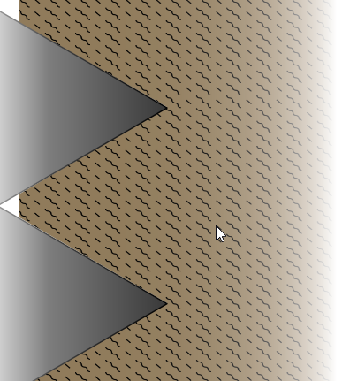
Use Vector Selection Order
If this option is checked, ✓ the vectors will be machined in the order you selected them. If the option is not checked the program will optimize the order to reduce machining time.
Position and Selection Properties
Safe Z
The height above the job at which it is safe to move the cutter at rapid / max feed rate. This dimension can be changed by opening the Material Setup form.
Home Position
Position from and to that the tool will travel before and after machining. This dimension can be changed by opening the Material Setup form.
Vector Selection
This area of the toolpath page allows you to automatically select vectors to machine using the vector's properties or position. It is also the method by which you can create Toolpath Templates to re-use your toolpath settings on similar projects in the future. For more information, see the sections Vector Selector and Advanced Toolpath Templates.
Name
The name of the toolpath can be entered or the default name can be used.
Delete Toolpath
This tool is used to delete calculated toolpaths from the Toolpath List. Simply select the toolpath to be deleted and click the Delete Toolpath button to remove it.
Alternatively, you can delete one or multiple toolpaths in the Toolpath List by right mouse clicking on a toolpath. Then from the drop-down menu click on the Delete option. This will present the options as shown in the image: Delete This, Delete All Invisible, Delete All Visible, Delete All.
Delete This will delete just the toolpath whose name you right mouse clicked on.
Delete All Invisible will delete any toolpaths in your Toolpath List that do not have a check-mark ✓ next to their name and are therefore currently not visible in the 2D or 3D Views.
Delete All Visible will delete any toolpaths in your Toolpath List that have a check-mark ✓ next to their name and are therefore currently visible in the 2D or 3D Views.
Delete All will delete all the toolpaths in your Toolpath List.
If you have incorrectly deleted a toolpath (or multiple toolpaths) then you have the option to Undo the toolpath(s) deletion via the Undo command on the Edit drop-down menu, the Undo icon on the Drawing Tab or the Undo shortcut key combination Ctrl + Z.
Mirror
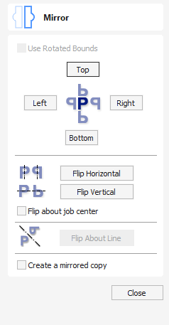
Selected vectors/bitmaps/component grayscale previews can be mirrored to a new orientation.
Selected objects can also be mirrored about axes of symmetry relative to the bounding box of the selection, using the standard options on the Mirror Form.
- Select the object or objects to mirror.
- Click on the Mirror icon to open the Mirror Form.
- Select the Create a mirrored copy option to leave the selection and create a new set of objects.
- Click the button to accept the changes.
Watch this video to see this in action:
Use Rotated Bounds
This option is available only when a single object is selected. When it's checked, it will flip the object around its local rotated bounds as shown in the Selection Tool. If the object isn't rotated, it will just operate normally.
Flip About Line
Select the Vector to mirror, and hold Shift and then select the Line vector you wish to use as the mirror. This option then becomes available to select and will flip the desired vector across the Mirroring Vector.
Shortcuts
The following shortcuts can be:
- H - Mirror Horizontally
- Ctrl + H - Create mirror. Copy Horizontally
- Shift + H - Mirror horizontally around center of material
- Ctrl + Shift + H - Create mirror copy horizontally around center of material.
- V - Mirror vertically
- Ctrl + V - Create mirror. Copy Vertically
- Shift + V - Mirror vertically around center of material
- Ctrl + Shift + V - Create mirror copy vertically around center of material.
Usable In Both Views
This tool can be used in both the 2D and 3D View.
2D View offers a more direct way to view your vectors while 3D Offers more flexability to work with Vectors in 3D Designs and to make use of the Edit Boxes.
Layer Management
Vectors, Bitmaps and Component Grayscale's can be assigned to different layers.
All the objects assigned to a layer can then be simultaneously selected, labeled, colored, temporarily hidden or even locked (to prevent accidental editing) using the Layer Management tools. Even for relatively simple designs, organizing the elements of your artwork onto layers can make managing your project much easier.
The Layers Tab
To get a complete overview of the current layer structure of your artwork while you are working, or to carry out more extensive organization of the layers, you can also use the Layers tab. The Layer List is identical in both the Layer Control and the Layers tab, but the latter can control layer ordering and be left visible, pinned or even undocked, while you continue to work on the artwork itself
List Item Command and Icons
Each layer in the list has five elements:
Status Icon

The leftmost icon indicates whether the layer is currently visible or hidden. Click on this icon to toggle the visibility of the layer.
The presence of a padlock shows that the layer is locked and cannot be accidentally edited.
Right-click the layer in the list and select the Unlock command to alter this.
Layer Colour

The color swatch can be used to color all the vectors on a layer. Click on the swatch icon Layer Color Icon and select a pre-set color from the color selector dialog, or choose to create an entirely custom color.
Layer Content

The layer content icon will be grayed-out as an additional indicator that the layer is not currently visible. Layer Empty Content Icon a blank white sheet indicates that the layer does not currently contain any objects or vector geometry. If you import files from 3rd party CAD drawing packages via DXF or DWG format it is common for the file to include empty layers. This icon allows you to identify these empty layers and delete them.
Layer Name
To change the name of a layer, you can double click on this part of the layer item in the list to trigger in-situ editing. This works in the same way as file renaming in Windows Explorer. Alternatively you can right-click or use the layer's Pop-Up Menu icon to select the Rename command.
Pop-up Menu

Click the pop-up menu icon Pop-up Menu Icon for access to Activate, Lock, Insert, Delete and Merge layers as well as further ways to choose which layers to show and hide.
Select All on a Layer
Double-clicking on a layer in the Layers List will select all the objects on that layer. Alternatively you can choose the Select Layer Vectors command from the layer's pop-up menu.
Layer Ordering Arrows

Adjacent to the Layers List heading label are two arrow buttons. These move the selected layer up or down in the Layers List. This can be important to set the drawing order of objects that might otherwise obscure one another (specifically Bitmaps and 2D Component Previews). Objects on the top layers in the list are always drawn before objects in the lower layers and will, therefore, be 'underneath' them in the 2D View. You can use the Layer Ordering Arrows to resolve this issue.
Add New Layer
New Layers can be added using the Add New Layer button. Alternatively a new layer can be created directly from the 2D View by right-clicking an object and selecting either the Copy to ► Layer ► New Layer... or Move to ► Layer ► New Layer...
Layer Name
It is always preferable to take the opportunity at this stage to give your new layer a meaningful name relating to its content or purpose. Later on this name will make it easier for you to manage your layers as your design becomes more complicated
Drawing Color
All the vectors on this layer will be colored according to this setting. This can be a very useful way of distinguishing between the vectors that are on different layers, directly in the 2D View.
New Layer is Visible
With this option checked, ✓ the new layer will automatically be visible as soon as it is created.
New Layer is Active
With this option checked, ✓ the new layer will automatically become the active layer and any subsequent vector creation or manipulation will occur on this new layer.
Insert New Layer
An even quicker way to add new layers is via the Insert Layer command from a layer's right-click Pop-Up Menu. This command will create a new layer above the selected layer which will be visible, unlocked and colored black. After creation the new layer item's name is ready to be immediately edited by typing a new name in.
Moving Objects to Layers
Objects on any layer can be moved onto another layer by right-clicking the object in the 2D View and selecting Move to Layer from the pop-up menu. It is also possible to place a copy of selected object to another layer by selecting Copy to Layer from the pop-up menu.
Gadgets
Gadgets are small programs that add additional functionality to Cut2D Pro, VCarve Pro and Aspire. They can be used to add new features to the software or automate common sequences of tasks. Examples include adding the ability to cut dovetail style joints with a standard end mill and applying toolpath templates to every sheet in a nested job followed by automatically post-processing and saving the files for your machine tool.
Install New Gadget... | Opens a standard Open File Dialog that allows you to chose a downloaded gadget you want to install. |
Gadget Shortcuts | Opens Gadget Shortcuts dialog. |
Installing Gadgets
You can expand your Gadgets library by downloading and installing more from the Gadgets website.
These Gadgets will install into your public documents folder (Public Documents/Vectric/Aspire/Gadgets). If you wish to delete any of these Gadgets, simply navigate to the location above and delete the folder.
Each Gadget has specific requirements in order for it to run, it is recommended that you read the instructions in full before use. Some Gadgets require that you select vectors before running the Gadget, others may need to be run before a job in the software is created. When there is a requirement that has not been met before running, you will receive an error message, stating which requirement has not been met.
Note
It is important to point out that the gadgets are NOT as polished as functionality which has been integrated into the main program. The gadget concept is intended to allow Vectric to produce simple add-ons which address minority requirements without cluttering up the main interface. As the Gadget library grows over time, we do not expect users to install every gadget, but only those that may be relevant to tasks they actually perform.
Running Gadgets
Installed Gadgets are accessible from the main Gadget menu, which is built dynamically each time Aspire starts up.
Alternatively Gagdets can be assigned shortcuts.
Gadget Shortcuts
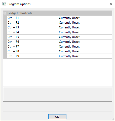
Shortcut can be set to run a chosen gadget from the list of gadgets. To set the gadget shortcuts select the Gadget Shortcuts button from the Gadgets menu.
You may then assign one of the predefined shortcut keys to run a chosen gadget. The available shortcut keys are Ctrl and a function key.
Preinstalled Gadgets
A number of Gadgets are included as part of the default installation of Aspire. These are all available from the Gadgets menu:
Wrapping Sub-menu:
Note
We ship some gadgets which help perform common tasks for people with rotary axis. If a user has no interest in rotary machining, they can delete the 'wrapping' gadgets from their gadgets folder and those options will no longer be available from the Gadgets menu.
Developing Gadgets
Gadgets can also be created by our users using the LUA scripting language, we provide an SDK and tutorials on the gadgets website.
Please Note
This will require knowledge of programming.
The SDK and the Tutorials are provided as is, Vectric cannot provide support on the development of user Gadgets.
Gadgets have their own section on the Vectric Forum, you can get news on the latest releases from Vectric and fellow users.
Offset Model
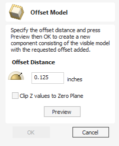
The Offset model tool creates a 3D offset of the composite model.
To use the tool, specify the distance that you want to offset the model.
Click on the button to see the results of the offsetting.
Click to proceed or click to exit the form.
The Clip Z values to the Zero Plane option will ensure that the final result will always be positive. When used on models with areas that end up lower than the zero plane these parts of the model will be removed leaving only the positive values. This can be helpful when you have a flat plane as part of the model to avoid it being effectively lowered by the offset amount.
Using this function you can offset with either positive or negative values.
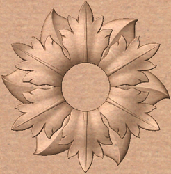
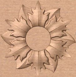
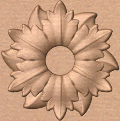
Note
Clicking the Preview button repeatedly will apply your chosen offset multiple times. Click the Cancel button to remove all effects of the previews.
Draw Polygon
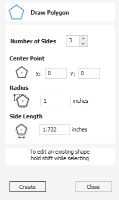
Polygons (e.g. Triangles, Pentagons, Hexagons etc.) can be created interactively with the cursor and Quick Keys or by entering the number of sides, exact coordinates and radius using typed input.
Watch this video to see this in action:
Interactive Creation
The quickest and easiest way to draw a polygon is by using the mouse in the 2D View.
- Click and hold the left mouse button to indicate the center point.
- Drag the mouse while holding down the left mouse to required radius.
- Release the left mouse button to complete the shape.
Note
Holding ALT and dragging creates a polygon from the middle point.
Quick Keys
Instead of releasing the left mouse button when you have dragged your shape to the required size, you can also type exact values during the dragging process and set properties precisely.
- Left-click and drag out your shape in the 2D View.
- With the left mouse button still pressed, enter a quick key sequence detailed below.
- Release the left mouse button.
Default
By default, entering a single values will be used to set the radius of your polygon. While you are dragging out the polygon, type Radius Value Enter to create a polygon with the precisely specified radius.
Example
- 2 . 5 Enter - Creates a polygon with a radius of 2.5. All other settings as per the form
Specifying Further Properties
By using specific letter keys after your value, you can also indicate precisely which property it relates to.
- Value D - Creates a polygon with the diameter specified, with all other properties as per the form.
- Value S Value R - Create a polygon with the specified number of sides (S) and the outer radius (R)
- Value S Value D - Creates a polygon with the specified number of sides (S) and the outer diameter (D)
Examples
- 1 R - Outer radius 1, number of sides as per form
- 1 D - Outer diameter 1, number of sides as per form
- 8 S 1 R - An 8 sided polygon with outer radius R of 1
- 6 S 2 . 5 D - A 6 sided polyon with an outer diameter of 2.5
Exact Size
Polygons can also be drawn by entering the required XY origin , selecting either Radius or Diameter and entering the required size.
Click to update the circle
Editing Existing Polygons
To edit an existing polygon select the polygon, edit the parameters and click to update the circle.
Usable In Both Views
This tool can be used in both the 2D and 3D View.
2D View offers a more direct way to view your vectors while 3D Offers more flexability to work with Vectors in 3D Designs and to make use of the Edit Boxes.
Keyhole Toolpath
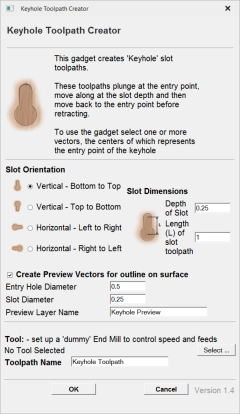
This gadget simplifies the process of creating 'keyhole' toolpaths which are cut into the back of a sign or plaque to allow easy hanging on a wall. These slots are cut using a 'keyhole' cutter as shown on the left. The toolpath for these slots needs to plunge into the material at the mounting screw entry point to a depth that will ensure that the wide part of the cutter is below the material surface. The tool then moves along the 'slot', once it reaches the end of the slot, the tool retraces its path back along the slot to retract at the original plunge point.
Like all Vectric Gadgets, the top of the form gives brief instructions on how it should be used. For this gadget, you need to select one or more circular vectors in your design to indicate where you want the entry points for the keyhole slots to be before the Gadget is run. If you start the gadget without selecting one or more vectors to indicate these positions, the following warning will be displayed:
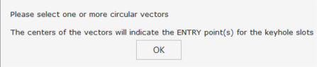
Once the form is displayed you can enter the parameters for your keyhole toolpath.
The data to be entered falls into three separate categories.
Slot Parameters
In this section of the form you specify the direction the slots will be machined and also the depth and the length for the slots.
Preview Drawing
To help with visualisation of the slot, the gadget can draw a vector outline of how the slot will appear on the surface of your job. This drawing is optional and if you un-check the Create Preview Vectors for outline on surface check box you do not need to fill in the parameters in this section. If you do want previews drawn, you can specify the entry hole diameter which will be created by your keyhole cutter and also the diameter of the slot the tool will create on the surface. You can also specify the name of the layer the vectors will be created on.
Toolpath Parameters
The final section of the form is used to specify a tool which the feed and plunge rates are picked up from, and also a name for the toolpath which will be created. As keyhole cutters are not supported natively by the program, just set up an end-mill with the required feed rates to use.
After entering all your parameters and pressing , the gadget will create a toolpath within the program to machine your slots and also the vector preview if you enabled this option. The screen shot below shows the preview vectors in the 2D view along with the toolpath in the 3D view.
Right Mouse Click Menu
Clicking the ►RIGHT hand mouse button in different places in Aspire will display a menu with choices which depend on the area of the software being clicked on and/or the object or selection that the mouse cursor is positioned over. This page details some of these areas and the menus that you will see when RIGHT mouse clicking.
2D/3D View
This menu is displayed when you Right mouse click in 2D or 3D View either in the white background of the part or over a selected vector. Most of these options repeat functions and icons described elsewhere in this manual, you should refer to the appropriate section to view how these work.
Many of these options are also Context Sensitive and will appear Greyed out when you right click something which cannot be targeted with that option.
Activate Layer of Selection
Set the Active Layer as the layer the selected item is on currently.
Appearance
This will bring up the following tool Box.
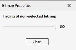
This slider will allow you to increase/decrease the amount of fading applied to this Bitmap/Component when it is not the currently selected item.
This can help if you want it to disappear into the background when working on other things, or to remain promanent and visible when working on other things. The default value for this is 50% and cen be set per item.
Appearance
This will bring up the following tool Box.
This slider will allow you to increase/decrease the amount of fading applied to this Bitmap when it is not the currently selected item.
This can help if you want it to disappear into the background when working on other things, or to remain promanent and visible when working on other things. The default value for this is 50% and cen be set per item.
Component
This allows quick access to options for Components such as changing it Combine Type, or opening its full Component Properties form.
Text
Remove From Curve:
If you have previously added your text to follow a curved Vector, this will allow you to remove it from that curve and return it to its original uncurved state.
Break Block into Lines:
If your text has more then one line of text in it, this will allow you to break that Text Objects into multiple text Objects, each made up of a Single line of the original Text.
Convert to Vectors:
This will convert a Text Object into a set of standard Vectors which can then be edited as normal vectors.
Layer and Side Operations
The Copy to and Move to options are unique to this Right click menu.
They have Level, Layer and Sheet modes, as well as Other Side which are Context sensitive, so will only show options which are applicable to the right clicked item.
- Copy to allows you to copy an object onto an existing Layer/Level/Sheet or to create a New one to copy it onto.
- Move to gives you the same choices but moves the original object rather than making a copy.
- Other Side copies the selected objects onto the other side in a two-sided job. The objects will be transformed so that they match up when looking through the material.
- Move to Front/Back is 2D View Exclusive and will bring items to the front or rear of other items on that same layer.
- Move to Up/Down is 3D Exclusive and will Raise or Lower the Components posiotion within its current Level.
Span Editing Menu
If the current selection mode is set to Node Editing, one of two different menus will appear when the user clicks the RIGHT mouse button depending on whether the cursor is currently over a vector Node or a Span of a selected vector in the 2D View.
These menus have functions in them that correspond specifically to this selection and position. The menu shown here will appear when the cursor is over a Span of a vector in Node editing mode.
You can see a variety of choices:
- Convert the span to a Line, Bezier (curve) or Arc
- Insert a Point
- Cut the Vector at that point
- Delete the Span
- Insert a Midpoint
- Keep Bezier Tangency, which will fix the start and end directions of Bezier curves when they are being dragged directly, can be toggled on or off.
From this menu you can also Reverse the direction of the selected vectors, Close any selected open vectors, Join two selected open vectors or Exit node editing mode.
Many of these have corresponding Shortcut keys (shown to the right of the command in the menu) which can be selected from the keyboard when the mouse is in position (over a node-edit vector span) instead of Right Clicking the mouse button to access the menu.
Node Editing Menu
This menu will appear when the cursor is over a Node of a vector in Node editing mode.
You can see a variety of choices:
- Delete the Point
- Smooth it
- Insert a point at a virtual midpoint
- Cut the vector at that point
- Change the point to be the Start Point of the vector or extend the vector using the Polyline tool.
- Horizontal or vertical mirror mode for node editing can be toggled on or off.
From this menu you can also close any selected open vectors, Join two selected open vectors, Exit node editing mode or lastly see and edit the exact XY co-ordinate position of the node by selecting Properties.
Many of these have corresponding Shortcut keys (shown to the right of the command in the menu) which can be selected from the keyboard when the mouse is in position (over a node-edit vector node) instead of Right Clicking the mouse button to access the menu.
Level Menu
When a Level in the Component Tree is selected and you RIGHT mouse click on it then the menu shown below will appear.
The first section allows you to make alterations to the selected level where you can change how the level combines with levels below it, you can choose to show or hide the level's visibility (and consequently the Components on it). Using the Select components option will select all the components within the level.
The next section contains the level effects which apply an effect to the level without affecting the individual components.
- The Clipping effect will dynamically clip the combined components on the level to the closed vectors which were selected when the effect was checked on.
- Mirror Mode allows you to mirror the combined components on the level in various ways.
- Wrapping is available for rotary jobs only and will allow components outside the job area that would otherwise be truncated to wrap around to the other side.
The next section allows you to insert new levels, delete the level and rename the selected level.
The final section of the menu allows you to export the complete contents of the level as a .3dClip file - when re-imported this would come into Aspire as a group.
Component Menu
This menu appears when a Component is selected in the Component Tree and you RIGHT mouse click on it:
The first option allows you to select the way the component combines with the other objects on its Level. You then have the option to position the components grayscale in the 2D View, by moving that to the Front or the Back. You then have the options to Copy and duplicate a component along with the option to Export the selected component as a .3dClip file. If you have more that one component selected you have the option to Group/Ungroup the components. You can delete and rename a component. There is also the option to show components, where you can choose to Show This, Show Only This, Show All But This and Show All. You can Hide a component, where an extra menu allows you to Hide This or Hide All. You can open the properties form for the selected component and the last option allows you to move the component to a new or existing Level within the Component Tree.
Clipart Menu
Import to Level
When you RIGHT click on a piece of clipart in the clipart tab you have the option to import it to a new or existing level in your job. This will position the object in the center of the workspace and add it to the top of the list of Components on the selected Level or if you choose New Level will allow you to enter a name and Combine Mode.
Open Containing Folder
You can also the Folder which contains the clipart file in Windows.
Download
For clipart files included as part of the included clipart packs with the software, you will have the option to download them. See the Clipart guide .
Layer Menu
Activate
Set this layer as the Active Layer.
Show
Select which Layers to show from a set of 4 options, and make them Visible in the Views.
Hide
Select which Layers to hide, and make invisible.
Lock
Lock this layer so that vectors on this layer cannot be selected.
Unlock
Unlock this layer so that vectors on it can be selected.
Insert New Layer
Create a new empty Layer, above the layer which was right clicked.
Delete
Delete this layer
Rename
Rename this Layer
Merge Visible
Collapse all Layers which are set to Visible currently, and place all Objects on those Layers onto this Layer.
Select Layer Vectors
Select all Vectors on this Layer in the View.
Toolpath List Menu
When you RIGHT click on a toolpath name within the Toolpath List there are various options you are presented with to alter this toolpath. You can show a toolpath where you have the option to
- Show This,
- Show Only This,
- Show All But This
- Show All With This Tool
- Show All.
This toggles the visibility of the Toolpaths according to your choice. The next option allows you to Hide This or Hide All your toolpaths. Activate Sheet will make the sheet associated with the selected toolpath the active one.
You can Edit, Rename or Duplicate the selected toolpath. The Recalculate submenu allows you to recalculate the selected toolpath, visible toolpaths or all toolpaths with any updated geometry selections.
Create an Empty Group will create an empty toolpath group which you can later place toolpaths inside. Group Visible will create a toolpath group containing the visible toolpaths.
Ungroup allows you to remove a toolpath group while preserving the toolpaths it contains. The Delete submenu allows you to delete one or more toolpaths, where you can Delete This, Delete All Invisible, Delete All Visible and Delete All.
Offset Vectors
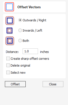
Selected vectors (open or closed) can be offset either inwards or outwards to create new vector shapes that might be useful for edge patterns or borders etc. To offset a vector shape, use the following steps:
- Select the vectors to offset
- Select the required direction - Outwards / Right or Inwards / Left
- Enter the Distance
- Click the button
Watch this video to see this in action:
Options
The offsetting options are slightly different in their behavior depending on whether the vector to be offset is open or closed. See below for more information.
Create sharp offset corners
Will retain any sharp corners in a design.
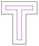
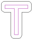
Offsetting Open Vectors
When offsetting open shapes, the options are either to the Right or Left side of the selection. The direction of open vector(s) is very important as this is used to decide the right and left side of the selection. Selecting Node Edit mode (pressing N on the keyboard) will display a Green node at the start of the vector. Looking along the vector(s) from the green node indicates the direction and the image below shows offsets to the left and right of an open vector.
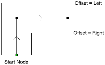
Usable In Both Views
This tool can be used in both the 2D and 3D View.
2D View offers a more direct way to view your vectors while 3D Offers more flexability to work with Vectors in 3D Designs and to make use of the Edit Boxes.
13. Advanced - Advanced Modelling of 3D Rotary Projects
Modelling 3D spiral features
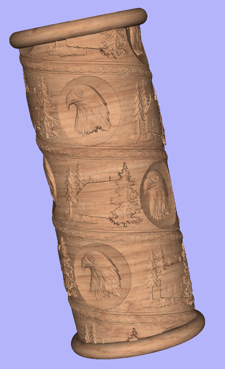
In this section we will show how to use level-wrapping feature to wrap a design in spiral manner around a column.
The workflow for creating spiral toolpaths has been presented in the Simple rotary modelling using 2D toolpaths chapter. The basic idea involved creating a line at a proper angle to the rotation axis, that exceeded the 2D boundaries. When 2D toolpath is created based on such a line, it will be wrapped around material cylinder, creating a spiral.
This guide will build on that basic idea. The task is to create a horizontal strip with desired pattern and then wrap it like a ribbon around the cylinder.
To help with that task, it is important to create some helpful vectors first. We need to create lines, that will become boundaries of our strip. In this example the strip was being wrapped four times around full length of material. This example assumes that rotation axis is parallel to X axis.
To start, select Draw Line/Polyline tool and draw a horizontal line at the bottom of the job from left to right. If it is desired for the spiral pattern to only fill part of the cylinder length, this horizontal line should be drawn only in th desired location. While the drawing tool is still active, type 90 into Angle box and type y * 4 into Length box and pressing =. We used y * 4 formula so the strip will wrap 4 times. Then press Add button to add a vertical segment.
Now, start a new line that connects the horizontal and vertical lines, forming a triangle. Once this line is created, horizontal and vertical lines can be removed.
The line that we just created will form a bottom of the strip. Now copy this line and place line so its bottom left end coincides with top left corner of the 2D job. This line will form a top of the strip. Then make another copy and place it in the middle. This middle line will be used later to position our design within strip. All three lines have been shown below.
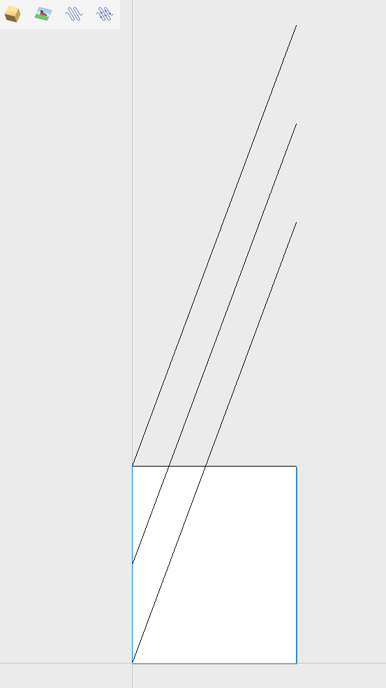
Next step is to find out the required length and width of the strip. We will need a few extra vectors to accomplish that.
Let's copy one of the created three lines and rotate by 90 degrees, to get a line that is perpendicular to the strip. Then place it in such way so it crosses the strip. This will help us measure the width.
Then copy the perpendicular line and place it so it touches the top line. Then extend the bottom line, until it crosses the perpendicular line we just added. This will help us measure the length of the strip.
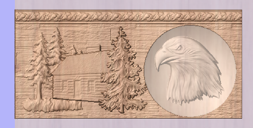
The easiest way to achieve that, is to create a textured component. To do that, select the design in the component tree and activate the Create Texture Area tool. This example used the default settings of the tool. The tool will create a new component that will fill the whole 2D job boundaries. The component itself will be filled with the design in tiled manner. Now use the Set Size tool to resize textured component to match the strip size.
Now the component have to be rotated and moved to fit between the lines you have drawn at the beginning. This process can be made easier by utilizing Copy Along Vectors tool. To proceed, activate the tool and select the textured component first, then select the middle line in the strip while holding Shift. Make sure that Align objects to curve option is selected and use Number of copies option. Since our strip has already have a correct size, we only need one copy. However the tool would place the middle of our component at the beginning of the line only. If you enter 3 as the number of copies, then the tool will place two copies of component at each end and in the middle. Afterwards the copies at the ends can be simply deleted. The picture below shows the strip in the 3D view after being correctly positioned.
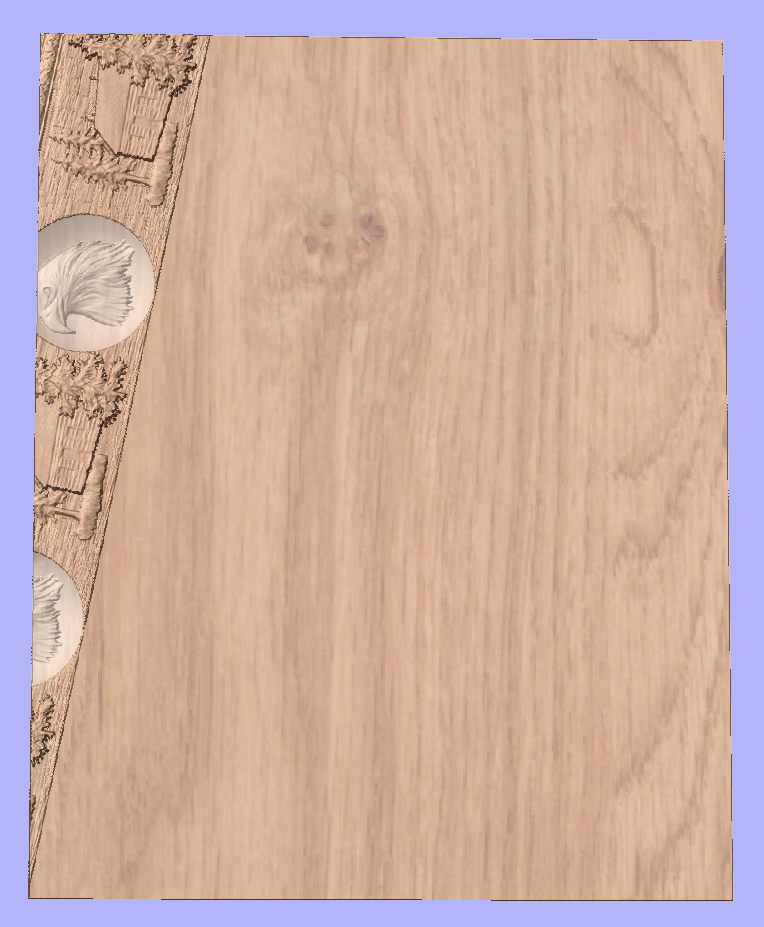
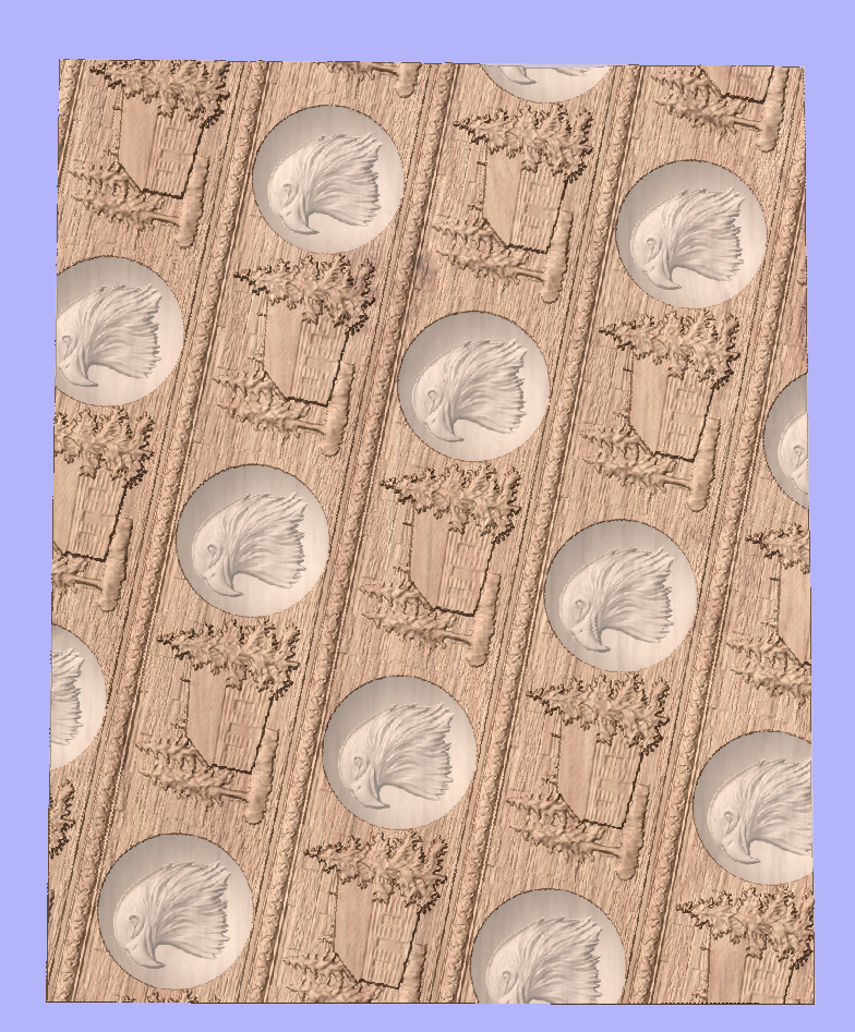
As can be seen, the strip disappears as soon as it leaves the material boundaries. In order to make it wrap around, we need to create a new level in the component tree and move the texture component into it. Then right click on the newly created level and right click. From the pop-up menu select wrapping. After that wrapping will occur.
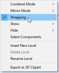
Note:
Wrapping can be enabled on any level in component tree and combined with mirror mode. If the level wraps on itself, then intersecting areas will be merged regardless of level's combine mode. If it is desired to create e.g. a woven pattern, then place left-hand spiralled component and right-hand spiralled components in different separate levels, both with wrapping enabled.
The last step is to make column endings. For that purpose the third level was created, with Combine Mode set to Merge. This way the spiral pattern will be 'hidden' at the ends. A circular 3D tab clipart was placed at each end, and stretch vertically to match the job boundaries.
Modelling twisted shapes
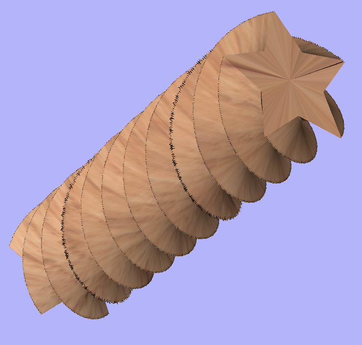
This section will show how to create twisted shapes, using a combination of level-wrapping and Vector Unwrapper tool.
In this example a new rotary job was created, with a diameter of 6 inches and length of 20 inches, rotating around X axis. To start, we need a cross-section vector. In this example a 5-armed star was used. To create a star, we can use Draw Star tool. This example used Outer Radius of 3 inches, to match the radius of the material.
The next step is to unwrap the cross section. In the case of the star however, the center is not the same as center of star's bounding box. To find the real center, one can draw a line from two of the star corners. Then open Vector Unwrapper and select the star. Then drag rotation center and snap it to the intersection of the lines, as can be seen below.
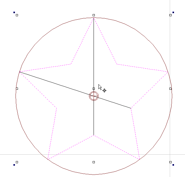
Once the star is unwrapped, we need to create rails, that will make spiral when wrapped. To do that, select Draw Line/Polyline tool and draw a horizontal line at the bottom of the job from left to right. While the drawing tool is still active, type 90 into Angle box and type y * 2 into Length box and pressing =. We used y * 2 formula so the star will make 2 revolutions Then press button to add a vertical segment. Finally, start a new line that connects the horizontal and vertical lines, forming a triangle. Once this line is created, our horizontal and vertical lines can be removed.
Next step is to copy the line and place it so its bottom left end coincides with top left corner of 2D job.
Once the the rails are ready, one could use a Two Rails Sweep tool. However, since rails exceeds the 2D job boundaries, the created sweep will be cropped as soon as those boundaries are exceeded.
To overcome that, select both rails, open Draw Rectangle tool and press . This will create a bounding box containing the rails. Now, write done the size of the box and save current project. Then create a new single-sided project with the slightly bigger than the bounding box. Use the Import Vectors option from the main menu and select the previously saved file. Now select the rails and press F9 to center them.
Now use Two Rail Sweep tool. When component is ready, save the file.
Now re-open the original rotary project. Use Import Component and select the single-sided project created in the step above. Move the component to the desired location. Then, create a new level, move the component there and enable wrapping.
Using single-sided modelling tools
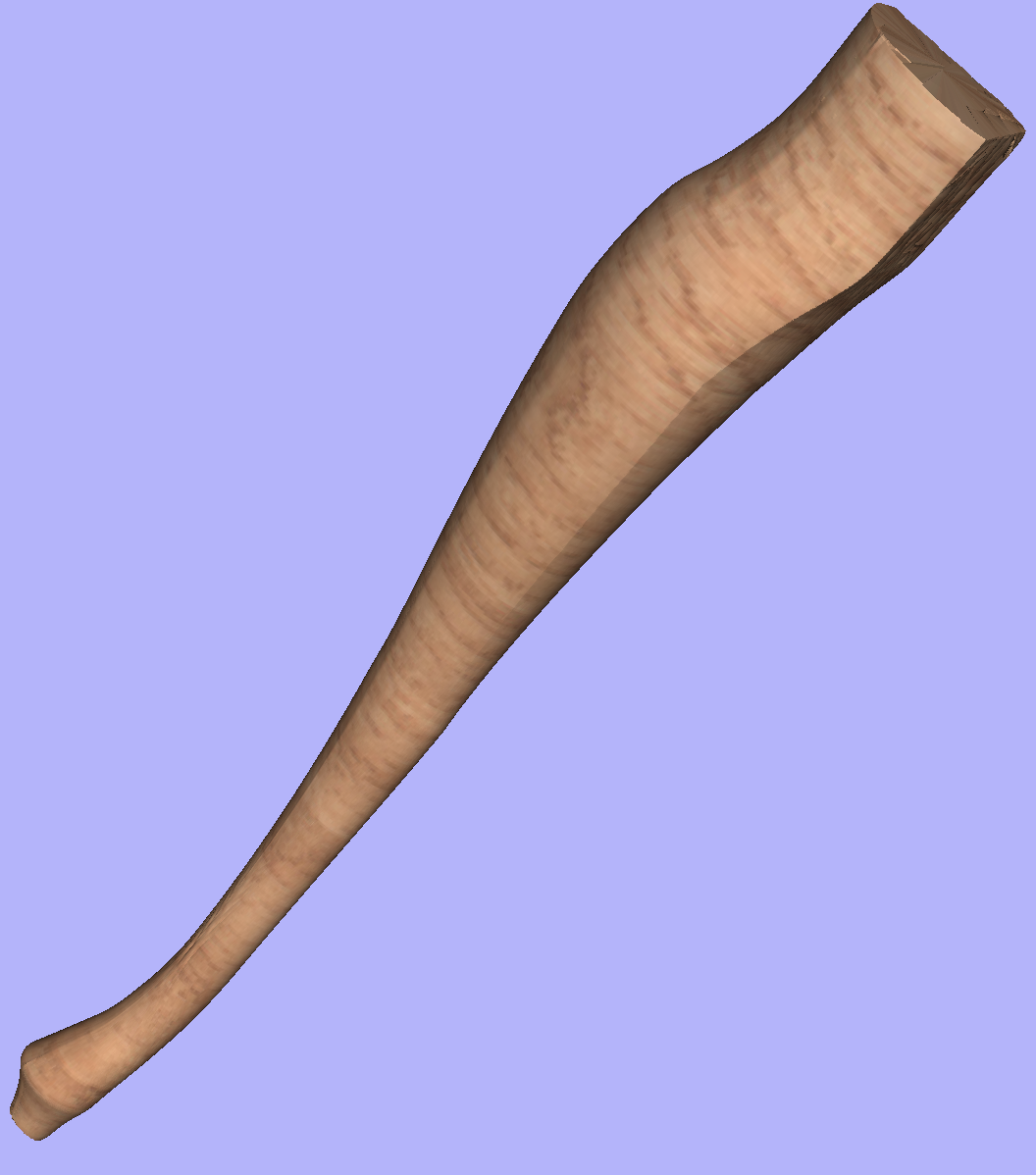
This section will present how to use single-sided modelling techniques in rotary projects.
Users familiar with modelling techniques used in single-sided projects may find them more convenient for modelling certain shapes. This example uses two vectors, representing side cross section of the table leg and a few of half cross sections for different parts of the table leg. Those vectors are presented below.
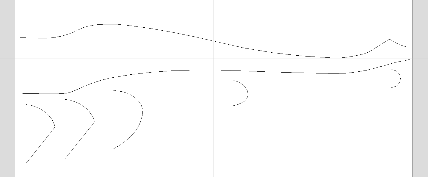
One can simply treat the side cross section as rails and use the Two Rail Sweep tool, placing the half cross sections at appropriate locations. This way half of the leg can be modelled very quickly, with the result that can be seen below (using flat 3D view).
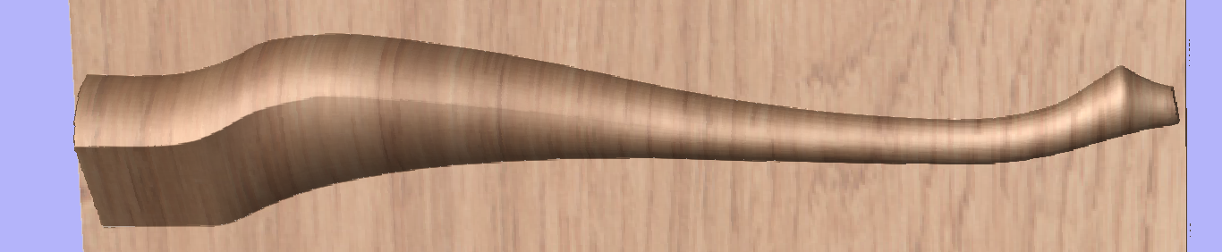
In order to use the created model in a rotary project, we need to export and then import it back. Although it is possible to do this with two sessions of Aspire, it can also be done within a single session with rotary project. To export the leg model, make sure no other components are visible (including the automatically added zero plane) and open the Export Model tool while holding down Shift. Pressing Shift allows to open the export tool in single-sided, rather than rotary mode.
Since half of the leg was modelled, Close with inverted front option can be used. The resulting STL mesh can be seen below.
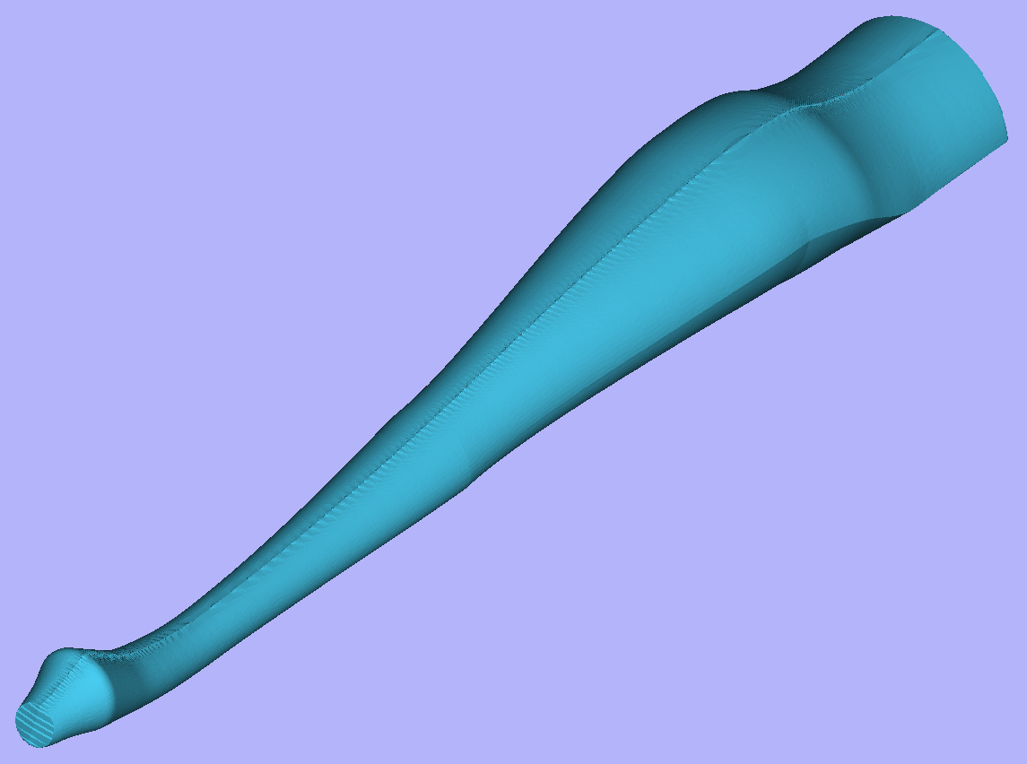
Once component is exported, it can be re-imported as Full 3D model. The model will have a seam, in the place were two halfs were merged. This can be removed using smoothing function of the Sculpting tool.
Positioning an Imported Model
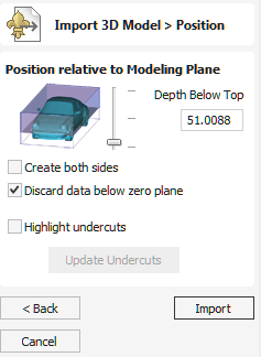
Zero Plane Position In Model
This slider bar determines where the 3D model will be cut-off when converting to a Component. You can move this up and down with the mouse or use the Middle or Bottom buttons to locate the plane in the correct position.
Note
Anything in the original model which is an undercut (goes underneath another part of the 3D model) will be discarded and a vertical wall will be created down to the plane from the silhouette (looking down Z axis) edge of the model.
Create both sides
If you are working in a 2 sided setup you can check ✓ this option and two components will be created - one looking down the Z axis from above to the zero plane and one looking up from below. Each side of the model will go onto a side. This will provide you with the geometry that can be edited to cut the original imported 3D part as a 2-sided job.
If you were importing a model that contains a non-convex surface for instance a bowl you can import the entire model on each side by sliding the slicing plane all the way to the bottom.
Discard data below zero plane
Checking ✓ this will remove any data below the original Zero level within the imported 3D model. If the model is effectively a negative model such as a dished or recessed design with a flat plane then you should uncheck this option to make sure you retain the 3D data below the plane.
Highlight Undercuts
Checking ✓ this will help highlight any part of the 3D model which will lose detail when being imported by turning those parts of the 3D model Dark Purple in the 3D View.
As undercuts cannot be supported, any part of the model under this will be obscured and essencially lost once imported.
This tool will also highlight all parts of the model in Dark Purple which have Normal Issues in the original file. If you have large areas of the top surface of your 3D model highlighted like this and you do not get the import result you are expecting with your 3D model, you may need to investigate the original 3D model file in the original software used to create it to ensure it is solid and whole, and does not have parts of itself "inside out".
Back, Cancel and Import
The final options are:
- will return you to the Import 3D Model > Transform form.
- will close the Import form and not import your model.
- with complete the process and convert your 3D model into a 3D Component within Aspire
License Registration
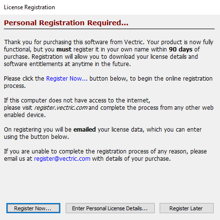
If you have recently purchased your machine which came with some licencse details for Aspire (Registered User Name & License Code), you will have activated your software through the Manual License method from the License Dialog.
You have 90 days to register the software to obtain your own personalised license details through your own V&Co account.
In order to register, you just need to click which will take you to a web page to register and create a V&Co account. This will allow you to retrieve your license details more easily and have access to our online features such tool database backup and online license entry.
If you are already registered, then you could just click which will take you the License Dialog.
If you click the button, you can continue to use your software but will be prompted again to complete the registration process.
Two Rail Sweep
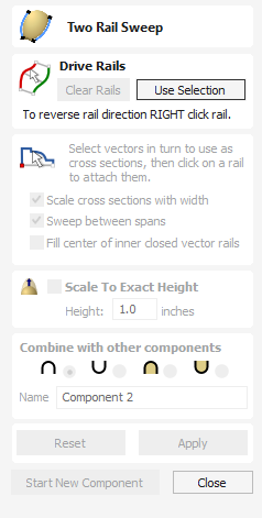
Two Rail Sweep uses a combination of vectors to define a swept 3D Component. The shape is based on two drive rails which can be open or closed vectors and multiple cross sections which are positioned on the drive rails and have to be created using open vectors.
Watch this video to see this in action:
Drive Rail Selection
The first stage of using this tool is to select the vectors which will represent the Drive Rails. From the 2D View use the mouse to select two open or closed vectors then click the button.
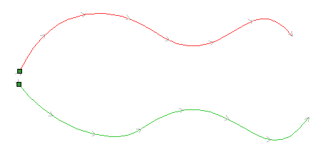
In the 2D view your rail vectors will now be colored red (first selected vector) and green (second selected vectors) and show a square green start node indicating the start point of each rail and arrow markers along its length to show the direction the shape will be swept.
The start point and direction may not be what you intended. To change the direction, right-click with the cursor on the drive rail you want to edit and select from the context sensitive menu, you will now see the arrows on the drive rail change direction.
You can also change the order the rails were selected by clicking on this will swap so the red rail becomes green and green becomes red, doing this will cause the cross-sections to hang in the opposite direction. On a closed vector you can change the start point by placing the cursor over an existing node in the drive-rail vector, right-clicking and selecting or you can right-click anywhere on the vector and select Insert Start Point to create a new node which will become the start point.
The button on the form can be used at any time to empty your current selection. This will delete your current shape and deselect all the drive rails and cross section vectors. This can be used if you do not want to create a Component before you exit the form or if you want to select new vectors in the 2D view to use as the drive rail for your shape.
Cross Section Selection
After you have chosen your drive rails the next step is to select one or more cross-section vectors to sweep along those vectors to form a 3D shape. In order for vectors to be used as valid cross-section shapes, they must be open.
Select a vector that you wish to use as a cross-section in the 2D View by left clicking on it with the mouse.
If you are using just a single cross section then you just need to make sure it is selected and then can proceed with the other settings in the form and calculate your shape. If you want to edit cross section positions or add more than one cross section then you will need to attach them to the drive rails.
Select a vector that you wish to use as a cross-section in the 2D View by left clicking on it with the mouse. Now click on the drive rail to attach the cross-section to that vector.
As you move the mouse over a selected drive rail it will indicate with a check mark ✓ that it is a valid place to add the cross section. Once a cross-section has been successfully attached to your drive rail, the 2D view will show a preview using line markers to indicate how the cross section will be positioned when it is extruded.
Two Cross-Sections are always created when you attach the first cross-section to the drive rail - one across the start nodes of each vector and one across the ends. The intermediate lines along the entire length of the rails indicate how the shape will flow between the defined cross sections. You can click the button to create your 3D swept shape.
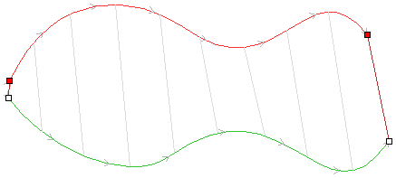
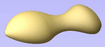
Using multiple cross-sections
It is possible to extrude between multiple cross section vectors along a drive rail blending from one vector shape to another.
Adding Cross-Sections
To add a new Cross-Section to an existing extrusion, simply select an open vector in the 2D View that you wish to use as a cross-section. With the vector selected, click on the point along the rail to which you wish it to be attached. A new Cross-Section will be inserted at this point and automatically attached to the second rail. On applying the change, the resulting 3D sweep will blend between all the defined Cross-Sections along the rail.
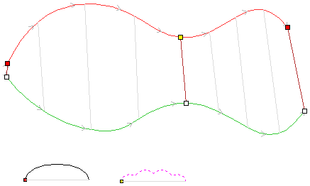
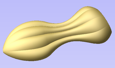
Note
To help differentiate which cross section is being used at each location the software will indicate a colored node at one end of each cross section and place the same colored node on the preview position. This node also indicates the direction the cross section is being 'hung' across the rails. The same cross section vector can be used in multiple locations along the drive rail.
Connecting Rail Nodes
By default, Aspire sweeps the cross-section along the drive rails connecting points at the same proportional distance along each rail's length. So, for example, the positions halfway or three-quarters of the way along each drive rail will be connected by the cross section in the resulting 3D shape.
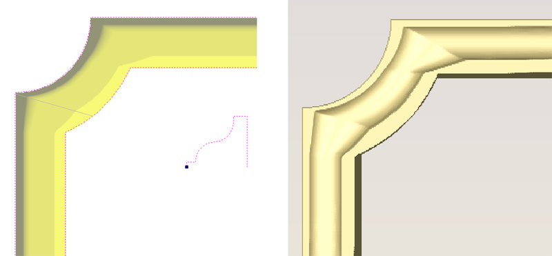
As the images above show, when the matching proportional positions along each rail do not match the appropriate features of the shape it can produce undesirable results. In this example the corners of the frame design are at different proportional positions along each rail and so the two-rail sweep does not connect the corners. Instead the cross-section appears stretched around the frame, as it is used to connect other points that do match in their proportional distance along each rail.
To resolve this, the software allows you to force the connection of pairs of points along the drive rails. This can either be done manually by inserting and re-positioning the cross-sections across the corners (see sections below for more information on this), or if both the drive rails have the same number of nodes it can be done automatically after you have added the first cross section by right-clicking on the first cross section preview position and selecting Add To All Rail Nodes. This will add that same cross section to every pair of nodes on each drive rail. When the cross section positions are set up correctly then Aspire will sweep the shape between each cross section location and create clean corners as shown in the images below.
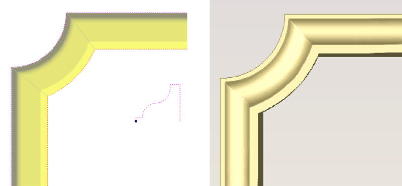
Removing Cross-Sections
To remove a Cross-Section, position the cursor over the cross section and press the RIGHT button on the mouse. Select the option to Delete Cross Section from the menu.
You can remove all the Cross-Sections on the drive rails by positioning the mouse arrow over a part of the curve that does not contain a cross section. This will bring up a different context sensitive menu and you can select the options to Remove All Cross Sections.
Altering Existing Cross-Sections
Existing cross-sections can be re-positioned on the drive rail. To do this click on the nodes at either end of the cross section preview in the 2D View (the ones on the rails), hold the mouse down and drag the node to a new position on the curve, let go of the mouse button to release that end of the cross section in its new position. You should make sure you do not drag a cross section past another existing cross section on the shape. If you need to move cross sections out of their current order then you should remove the existing cross section and insert the same shape at the new position so the shape can be created correctly. Any of your current cross-sections can be replaced by selecting a different open vector, moving the mouse over the end node of the cross section you want to change and clicking on it. The node color indicated on the cross section preview position on the curve will change to indicate which vector is now being used at that point in the shape.
Controlling the Swept Shape
There are check boxes in the form that allow you to Scale cross sections with width, Sweep between spans, and Fill center of inner closed vector rails. The Smooth option under the right-click menu allows you to control different aspects of the shape you create with the selected set of vectors.
Scale cross sections with width
As the cross sections are extruded along the rails the user can either choose to retain the exact shape and height of the cross sections or for a more natural look the Scale cross sections with width option can be checked ✓. This will alter the height of the cross section in proportion to the distance between the rails. This means that as the rails get further apart the shape gets higher and as they get closer together the shape gets lower. The image below left shows the result if this option is un-checked and below right with it checked ✓.
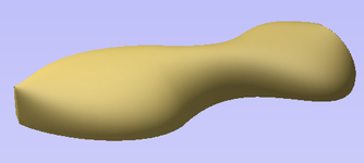
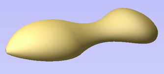
Sweep between spans
This option only becomes active if all selected cross section vectors have the same number of spans and nodes. When checked ✓ it will ensure that as the shape is extruded that it goes from a particular node/span in one cross section to the same node/span on the next cross section. In certain shapes this can give the user more control over the way the shape flows.
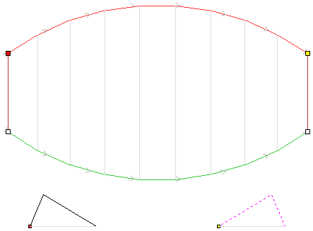
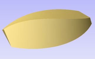
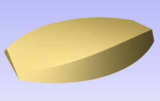
Fill center of inner closed vector rails
If you are sweeping two closed vectors to form a border or boundary shape, you can have Aspire automatically find the height that the cross-section forms on the inner boundary and then fill the shape to this height. To activate this check ✓ the Fill center of inner closed vector rails option in the form. This tool is perfect for sweep decorative bases, plaques or stands. Below left you can see a shape created with this option off and on the right an option with it activated.
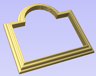
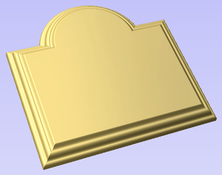
Smooth transition through the Cross Sections
As the swept shape passes through each cross section the default is for it to flow smoothly through the profile. This can be edited by right-clicking over the end node of the cross-section and unchecking the Smooth option.
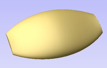
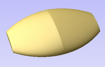
Scale to Exact Height
Checking ✓ this option scales the shape calculated so its maximum height is the value entered in the Height area of the form.
Common Modeling Options
All of the main modeling tools in the software use a common set of commands to assign a name and combine mode to the component being created along with options to apply the settings in the form, reset the shape, start creating a new component and close to exit the function.
Combine with other components...
This section includes options to allow you to name your Component and control the way it will be combined with other objects in the Component Tree.
Reset
Clicking the button will remove the current shape, doing this before you Close the form will ensure that a component is not created from the current selection. Clicking this does retain the current set of selected vectors or Components.
Apply
Clicking the button will create a shape based on the settings you have chosen. You can continue making edits to the component by choosing different parameters within the form and hitting Apply to update it.
Start New Component
Clicking the button will save the state of the component that has been created, deselect all components/vectors and start the creation process again on a new component. The values and options within the form will be retained in this case until you Close it.
Close
Clicking the button will close the form returning to the Modeling Tab icons and the updated Component Tree, reflecting any changes that you have made. If you wanted to remove the shape you just created then you can hit the Undo icon or use the keyboard shortcut to undo, CTRL+Z.
Job Setup - Double Sided
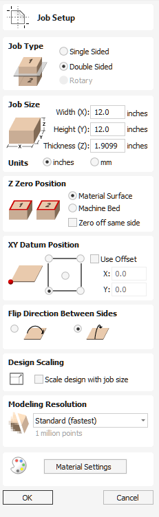
The Job Setup form is displayed whenever a new job is being created, or when the size and position of an existing job is edited.
In most cases a new job represents the size of the material the job will be machined into or at least an area of a larger piece of material which will contain the part which is going to be cut. Clicking OK creates a new empty job, which is drawn as a gray rectangle in the 2D View. Dotted horizontal and vertical Grey lines are drawn in the 2D design window to show where the X0 and Y0 point is positioned.
Check out this video for an introduction to two sided machining:
Job Type
Single Sided job type should be used when design only requires the material to be cut from one side. This is the simplest type of job to design and machine.
Double Sided Job type is useful when it is desired to cut both sides of your material. Aspire allows you to visualise and manage the creation and cutting process of both sides of your design within a single project file.
Rotary job type enables the use of a rotary axis (also called a 4th axis or indexer).Aspire will provide alternative visualisation, simulation and tools appropriate for rotary designs.
Job Size
This section of the form defines the dimensions of the material block you will be using for your project in terms of width (along the X axis), height (along the Y axis) and thickness (along the Z axis).
It also allows you to select which units of measurement you prefer to design in - either inches (Imperial/English) or millimeters (Metric).
Z Zero Position
Indicates whether the tip of the tool is set off the surface of the material (as shown in the diagram) or off the bed / table of the machine for Z = 0.0.
Zero off same side
This option allows Z Zero to reference the same physical location, regardless whether material is flipped or not
XY Datum Position
This datum can be set at any corner, or the middle of the job. This represents the location, relative to your design, that will match the machine tool when it is positioned at X0, Y0. While this form is open, a red square is drawn in the 2d view to highlight the datum's position.
Use Offset
This option allows the datum position to be set to a value other than X0, Y0.
Flip Direction Between Sides
This section gives choice between horizontal and vertical flipping when changing machining side. Aspire uses that information to correctly manage the alignment of the geometry relating to each side.
Design Scaling
When editing the Job Size parameters of an existing job, this option determines whether any drawings you have already created will be scaled proportionally to match the new job dimensions. If you wish to preserve the existing size of your drawings, even after the job size has changed, leave this option unchecked. With this option checked, your drawings will be re-sized to remain in the same proportion and relative position within your new material extents when you click
Modeling Resolution
This sets the resolution/quality for the 3D model. When working with 3D models a lot of calculation and memory may be required for certain operations. Setting the Resolution allows you to choose the best balance of quality and speed for the part you are working on. The better the resolution quality chosen, the slower the computer will perform.
As this is completely dependent on the particular part you are working on and your computer hardware performance, it is difficult in a document like this to recommend what the setting should be. Generally speaking, the Standard (fastest) setting will be acceptable for the majority of parts that Aspire users make. If the part you are making is going to be relatively large (over 18 inches) but still has small details, you may want to choose a higher Resolution such as High (3 x slower) and for very large parts (over 48 inches) with small details then the Highest (7 x slower) setting may be appropriate.
The reason that the detail of your part needs to be taken into account is that if you were making a part with one large item in it (e.g. a fish) then the standard resolution would be OK but if it was a part with many detailed items in it (e.g. a school of fish) then the High or Highest setting would be better. As previously stated these are extremely general guidelines as on slower/older computers operations with the highest setting may take a long time to calculate.
As the Resolution is applied across your whole work area it is important to set the size of your part to just be big enough to contain the part you plan to carve. It would not be advisable to set your material to be the size of your machine - e.g. 96 x 48 if the part you plan to cut is only 12 x 12 as this would make the resolution in the 12 x 12 area very low.
Appearance
Clicking will pop up a dialog allowing you to set the color or material effect which will be applied to the base 3D model. It is possible to change this at any time and also to apply different colors and materials to different Components using the Component manager. See Preview Toolpaths to learn more about different material settings and adding custom material effects.
Join / Close Vector with a Smooth Curve
Join with a Curve finds the closest end points on 2 selected, open vectors and joins them together with a smooth curve.
Watch this video to see this in action:
Aspire has two smooth joining methods:
- A smoother method (new for V9.5)
- A more symmetrical shallower join method
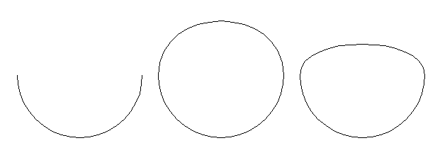
Usable In Both Views
This tool can be used in both the 2D and 3D View.
2D View offers a more direct way to view your vectors while 3D Offers more flexability to work with Vectors in 3D Designs and to make use of the Edit Boxes.
Create Job Sheet
Job sheets contain a summary of the information you will need when you come to run the toolpaths for your project at your CNC machine. Aspire will create a self-contained HTML document that can be viewed using most web browsers, including Internet Explorer, Chrome or Firefox. To create a job sheet for a given project, simply select Create Job Sheet from the Toolpaths menu and then select a filename and location to save the document. If your job contains multiple sheets, Aspire will automatically create a Job Sheet for every sheet that contains toolpaths. If you are working on a two sided job you will need to create a job sheet for both sides by simply switching between the sides and selecting the create job sheet icon, when you save the .html file the software will automatically add “_Top” or “_Bottom” to the name to differentiate between the two sides once the file has been saved.
Auto Open
If you wish to automatically open the Job Sheet after creation, simply hold down the CTRL key on the keyboard as you select the Create Job Sheet option from the menu.
Each job sheet document comprises the following information:
Job Layout
A thumbnail image representing the vectors on your current job / sheet, surrounded by an outer rectangle representing your material size.
Material Setup
A summary of the important pieces of information you will need to correctly position and datum your work piece at your CNC machine. This includes the dimensions of the material block used within Aspire to create and simulate your toolpaths. The home position from which your machine will start and return to. The clearance above the material for any rapid moves between plunges. For Two Sided Jobs you will also be displayed which side the setup sheet belongs to (top or bottom) along with the flip direction.
Toolpaths Summary
A summary of each of the toolpaths in the file, including the name of the toolpath, the tool required and an estimate of how long it will take to cut.
Toolpaths List
Details of each toolpath, including feed and plunge rates plus the intended spindle speed.
Copy Along Vectors
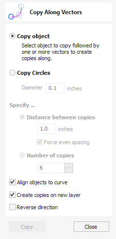
This tool automatically creates repeating patterns of objects by placing copies of them along the length of one or more selected vectors. The tool allows any existing object to be used but it also has an option specifically for the creation of circles, which is a common design element for patterns of this sort.
Watch this video to see this in action:
Copy Object
Any shape vector or group of vectors can be copied along a curve or curves. The first vector or group of vectors selected is the object that gets copied multiple times along the curves.
Copy Circles
Enter the diameter of the required circles

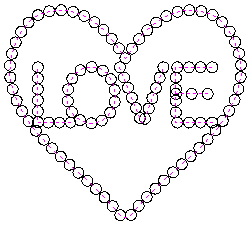
Distance between copies
This is the distance along the selected curve between each pasted vector. The Force even spacing option ensures that objects are pasted at the end points on the curve(s). If this option is not selected the pasted objects will be placed at the specified distance and may not match the exact length of the curve.
Number of copies
Selecting a specific number of copies automatically sets the specified number of copies along the entire length with an even spacing between them
Align Objects to curve
With this option selected the pasted objects are automatically aligned 'normal' or perpendicular to the curve they are being copied onto. If this is not selected, the copied objects stay in the orientation of the original.
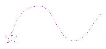
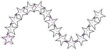
Create Copies on new layer
This option creates the multiple copies on a new layer making it much easier to select and organize the resulting vectors for machining purposes etc.
Reverse Direction
If your copies appear upside down, this option will perform the copy operation in the opposite direction along the selected vectors and the resulting copied shapes will be created the other way up.
Usable In Both Views
This tool can be used in both the 2D and 3D View.
2D View offers a more direct way to view your vectors while 3D Offers more flexability to work with Vectors in 3D Designs and to make use of the Edit Boxes.
Post-Processor Change Log
This will provide details of the changes that have been made between versions of this post-processor. This may be important for determining if you need to use an ealier or later version of a particular post-processor for your machine tool or controller.
This can be accessed from the Post-Processor list in the Machine Configuration Management dialog or the Post-Processor Management dialog.
Vector Selector
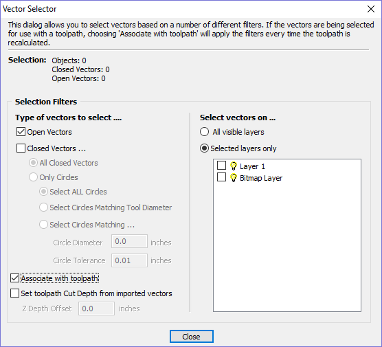
This tool allows you to easily select vectors which meet a set of criteria, such as open, closed, circular and also matching constraints based on layers. The dialog can be accessed from the Edit ► Vector Selector menu item, or from the button on each toolpath form. When the command is executed the dialog shown is displayed.
The dialog is used to configure a set of 'filters' that determine which vectors will be selected. A filter is enabled by clicking on its check box, or selecting a 'radio button' option, the current selection will be updated with all the objects in the file which match the current filter options.
Generally you will start at the top of the dialog and work downwards, specifying more and more explicit filters to determine the required selection exactly.
The simplest option is just to use the form to Select Closed Vectors in the job or Select Open vectors (you can specify both, in which case all vectors will be selected as long as they are on a visible layer).
The most common way to use the Vector Selector is to select all the vectors on a given layer as shown in the screenshot of the dialog below.
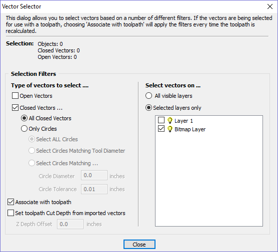
Note
When opened from Edit ►Vector Selector, the options Associate with toolpath and Set toolpath Cut Depth from imported vectors are not available. These options are only usable when applying the vector selector from a toolpath form.
Selection
The Selection: section at the top of the dialog is continuously updated to show the results of the current filter and the 2D view is also updated to show what is currently selected. The Objects: entry shows the total number of objects selected, if these objects include Text or Groups, this number may be less than the total of Closed and Open vectors displayed on the following line. For instance, a block of text is one object but will usually consist of many closed vectors. If a group contains both open and closed vectors, it will be selected as matching both Open and Closed filters.
Geometry Filters
The Geometry Filters section is used to specify constraints on the type of vectors to select. You can choose to select open vectors and/or closed vectors. Instead of selecting All Closed Vectors, the dialog can be used to select Only Circles and can even be used to specify an exact diameter and tolerance for the circles to be selected. This can be very useful for selecting vectors for drilling toolpaths, particularly if the vectors have not already been sorted into layers.
Layer Filter
The Layer Filter section allows you to pick one or more visible layers on which to select vectors which match the geometry filter. Alternatively, the All visible layers option disables the filtering by layer and selects all vectors which match the geometry filter regardless of the layer they are on, as long as that layer is visible.
Advanced Toolpath Templates
By associating a template with the result of a Vector Selector filter, we can make a template to automatically select the vectors it is intended to machine. A simple case would be to create a template which consisted of a Pocketing toolpath set up to machine all closed vectors on a layer called Pocket. After loading this template into a new job and choosing Toolpaths ► Recalculate All Toolpaths , the toolpath would be recalculated automatically selecting all closed vectors on the layer called Pocket.
The advanced templates are created by selecting the vectors for a toolpath using the Selector... button on the toolpath form. When a toolpath form is first opened, the Vector Selection: section on the form will show that vectors are being selected manually as shown below...
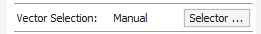
Pressing the Selector... button will display the Vector Selector form as shown previously. After making your geometry selection and before you close the form, select the Associate with toolpath option on the form as shown below.
After the Vector Selector form closes, the Toolpath form will indicate that Vector Selection is now 'Automatic' as shown below...
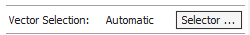
Note
Calculate the toolpath to apply the changes you have made.
When you re-calculate or edit a toolpath that has the Vector Selection mode set to automatic, the vectors which match the filter when the toolpath is re-calculated or edited will be selected. To cancel the Automatic vector selection mode, you can just select the vectors to machine normally with the mouse, or use the Selector... button to bring up the Vector Selectordialog again (the settings are remembered) and uncheck the Associate with toolpath option.
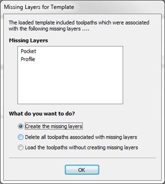
If toolpaths with the Vector Selection mode set to Automatic are saved as templates, these setting are saved with the template. When the template is re-opened and the toolpaths recalculated, they will automatically select all vectors which match the filters specified with the Vector Selector for that toolpath.
If you load a toolpath template which has toolpaths associated with layers which don't exist in the current file, the Missing Layers for Template dialog will be displayed. It lists all the missing layers and offers you the choice of having them created automatically, deleting toolpaths associated with missing layers or just loading the toolpaths as is.
Choosing to allow the dialog to automatically create the missing layers allows a toolpath template to be used to create 'standard' layers for machining operations and load the toolpaths ready to be calculated. All you then need to do is move vectors to the appropriate layers and recalculate all the toolpaths.
Choosing the Delete all toolpaths associated with missing layers option allows you to create a single template with many toolpaths and have the ones which aren't appropriate to the current job automatically deleted.
Options Dialog

Note
Many of the choices in this dialog will not take effect until the software has been exited and restarted.
Window Layout
Save Tab Layout | Save the layout and the 'pinned' state of the command and toolpath fly out tabs. |
Save Dialog Layout | Save the size, position and visibility for dialogs such as the Layer control and Toolpath Control dialogs. |
Save View Layout | Save the layout of the 2D and 3D view windows. |
Display Splash Screen | Display the program Splash Screen, while the program is loading. |
Top Side Ruler Color | The colour of the ruler on the top side in a two-sided project. |
Bottom Side Ruler Color | The colour of the ruler on the bottom side in a two-sided project. |
Tab location | Determines where handles for switching between tabs are located |
3D View Settings
Shaded Background Style | Allows to choose between Solid, Gradient and Image background styles. |
Background Color | Change the background color used for the 3D view. Used with Solid and Gradient background styles. |
Gradient Background Color | Change the bottom (lightest) color used for the 3D view. Used with Gradient background style. |
Draw Origin | Draw the origin arrows by default on startup. |
Draw Material Block | Draws Material Block boundaries by default on startup. |
Use Color Shaded View | Draw shaded model in 3D view by default on startup. |
Print 3D View Shaded Background | Include the shaded background when printing. |
Animate Camera Moves | Switch on/off animation in the 3D View when selecting View positon from the Iso View, Down X, Down Y or Down Z icons. |
Image File Path | Path to the image to be used as background. Used with Image background style. |
Use Software Renderer | If ‘Yes’ this option switches from hardware GPU rendering to Software rendering which instead utilises the CPU. Software rendering can be preferable in cases where there is limited GPU capability or there are compatibility issues. This will require a software restart for any changes to take effect. |
Anti - Aliasing mode | Anti-aliasing can improve the graphic resolution by preventing the distortions and artefacts within the rendering caused by two or more points becoming indistinguishable from one another. There are four different options for the level of anti aliasing you would like to apply; None, 2X,4X and 6X depending on the level required. |
Smooth Shading | Select ‘Yes’ to enable smooth shading in the rendering of components which will give them a smoother less faceted (many individual sides) appearance. Turning this feature on will utilize more graphics memory than when disabled. |
Shadow Shading | Turns on Shadow Shading by Default if turned on. |
View Controls Mode | This gives you the option to use the Modern Mode or Legacy Mode for the 3D view controls. |
Show Usage Information | When this option is enabled it will show a description of how to use the current tool at the bottom of the viewer. |
Toolpath Settings
Show Toolpath Operations with Preview | When the toolpath Preview form is visible, keep the 'Toolpath Operations' section visible (requires more screen space). |
Auto Open 3D view | Automatically swap to 3D view after calculating a toolpath. |
2D Solid Preview Color | Color used to draw the solid 2D toolpath preview with. |
Create 2D Previews | Create 2D previews of toolpaths in 2D view. |
Select Sheet When Edit Toolpaths | If a toolpath is associated with a sheet, select sheet when edit toolpath. |
Toolpath Geometry Fixing Timeout | Number of seconds the program will spend trying to fix problems with geometry when calculating toolpaths. |
Drop Tool | When projecting a toolpath onto the model, drop the tool on surface rather than project. If this is set, the toolpath will follow the surface of the model better, but could be slower to calculate. |
2D Toolpath Tolerance | Tolerance to apply to 2D toolpaths after calculating to reduce file size. |
3D Toolpath Tolerance | Tolerance to apply to 3D toolpaths after calculating to reduce file size. |
VCarve Toolpath Tolerance | Tolerance to apply to VCarve toolpaths after calculating to reduce file size. Note We strongly recommend that the Toolpath Tolerance should be left at their default settings unless different values are recommended by your machine tool manufacturer. If you do have a machine which struggles with the default settings, try doubling the values and cutting a test-piece to assess the tradeoff between machining times, file size and final machined quality. We have done some limited testing and on a sample complex 3D model, increasing the '3D Toolpath Tolerance' to 0.001 inches gave a 40% decrease in file size and no noticeable difference in quality on the test machine and job. In the test case there was no measurable difference in machining time on the CNC machine the test was carried out on. |
Maximum Toolpath Undo Stack Size (MB) | Maximum size in MB of Toolpath data undo stack for storing toolpath delete state. |
Append duplicated toolpath | When duplicating a toolpath, this determines whether it places the new toolpath next to the original or append it to the end of the list. |
Append new toolpaths to selected group | If a toolpath group is selected, add newly created toolpaths to the end of the selected group rather than to the end of the list. |
Use new raster | Generate raster toolpaths that are more consistent in regards to machining direction, even for complex shapes. |
Check depth of all toolpaths | If this is set to Yes then when job size changes are made then all toolpath depths are checked. If it is set to No then only the toolpaths which are visible have their depth checked |
Default toolpath filtering mode | Allows you to choose the toolpath filtering mode used when new file is created or opened. |
General Settings
Use Graphics tablet | Switch on support for graphics tablet drivers, if installed - for use with the sculpting tool. |
Process User Files | Enable/disable processing of files in the 'Vectric Files' folder in your common user document folder. |
Recent File List Size | This sets the maximum number of items that will be displayed in the Recently opened files... list in left hand side bar of the interface when there is no file currently loaded. The list will not increase in size until the software has been re-started and more files have been opened and/or saved. |
Recent Font List Size | Sets the maximum number of recently used fonts that will be listed at the top of the font selection box. |
Show additional file operations | If set to Yes then this will show an additional row of icons in the Design tab along the top for File New, File Save, Undo and Redo. |
Show the clipart Subfolder Contents | If set to Yes then this will show the contents within the selected Folder in the Clip Art browser along with up to 3 sub-folders if they exist and contain appropriate file types. If set to No it will only display the contents of the selected folder, not sub-folders. |
Always open local documentation | Force open the local copy of the documentation when accessed through the Help menu. Aspire automatically opens the local documentation if you have no internet connection or if the server is taking too long to respond. |
Smooth Join Vectors | Produce a smoother join between 2 vectors. This is option is there mainly to support older behavior. |
Default to last used text anchor position | Control the default location of the anchor when creating a text object. This is to either default it to the last set location, or always default to a specific location. |
File Dialog Default | This option controls the default directory that is opened when opening or saving files. The default Global options will open the last used folder as per the Operating Systems default behavior. If you choose Operation, the software will remember the last used folder for that particular operation. We divide operations in broad categories, such as, vector import / export, model import / export, toolpaths, tools, etc... If you choose Job, we will always default to your saved job's location. |
Confirmation Choices
Sheet Toolpath Deletion Check | When a sheet is deleted, you can choose whether the associated toolpaths will also be deleted. |
Toolpath Vector Intersections Check | If vector intersections are detected calculating a V-Carve or Pocket toolpath you can choose to be asked what to do next or to open the Vector Validator. Alternatively, you may forgo the intersections check entirely. |
Radiused Offset Intersections Check | If vector intersections are detected when performing a radiused offset you can choose to be asked what to do next or to open the Vector Validator. Alternatively, you may forgo the intersections check entirely. |
Sharp Offset Intersections Check | If vector intersections are detected when performing a sharp offset you can choose to be asked what to do next, to open the Vector Validator or to proceed with the offset anyway. |
Warn about unsuitable components for embossing | When attempting an embossing operation on a low relief component, display warning to indicate that this model may not be suitable. |
Ask which version of the tool database to download | When downloading a tool database from your portal, display a dialog to allow you to specify a database associated with a different product. Otherwise always download the database associated with the current product. |
Save All Visible Toolpaths as a Template
The Toolpaths ► Templates ► Save All Visible Toolpaths as Template menu command (or the associated icon) allows a group of toolpaths to be saved as a single template. As an example, the toolpaths may have all the settings used for Profiling and Pocketing operations for a particular type of job and material combination. These toolpaths settings can then be recalled simply by opening the template and selecting the appropriate vectors for each toolpath.
If toolpaths with the Vector Selection mode set to Automatic are saved as templates, these setting are saved with the template. When the template is re-opened and the toolpaths recalculated, they will automatically select all vectors which match the filters specified with the Vector Selector for that toolpath.
Multiple Sheets
If there are multiple sheets a message will be appear asking if you want to apply the template to every sheet in the job. If 'yes' is chosen the template will be applied to all the sheets and any toolpaths will be automatically calculated where possible. The toolpaths generated for each sheet will be prefixed by "Sn-" where 'n' is the number of the sheet for the toolpath. E.g if the template has a toolpath called "Cut Out" the associated toolpaths for each sheet will be:
"S1-Cut Out", "S2-Cut Out" etc.
If the template contains toolpaths that reference layers which do not exist in the current file the missing layers dialog will appear once and the option chosen will be used for every sheet the template is applied to. Choosing either 'Create the missing layers' or 'Load the toolpaths without creating missing layers' will mean that any toolpaths which reference those layers will be created as empty and have the visibility set to off.
If the toolpaths in the template use automatic vector selection then vectors matching the selection criteria can be created and the empty toolpath recalculated. If not using automatic selection an empty toolpath can be edited by double clicking on its name in the toolpath list or selecting the Edit Toolpath icon in the Toolpaths tab. Once the toolpath form is open, the vectors to be machined can be selected and the toolpath calculated using all the saved settings.
Duplicate Toolpath
The Duplicate Toolpath option creates and adds a copy of the selected toolpath to the Toolpath List. An index number is automatically added to the name of the new toolpath. For example:
Cut out - 1/4 inch End Mill will create a copy with the name Cut out - 1/4 inch End Mill (1)
Copying externally generated 3D toolpaths (as, for example, from PhotoVCarve) will also create a duplicate grayscale thumbnail image in the 2D View, which can then be used to position the toolpath within your job.
Create Shape
Common Modeling Options
All of the main modeling tools in the software use a common set of commands to assign a name and combine mode to the component being created along with options to apply the settings in the form, reset the shape, start creating a new component and close to exit the function.
Combine with other components...
This section includes options to allow you to name your Component and control the way it will be combined with other objects in the Component Tree.
Reset
Clicking the button will remove the current shape, doing this before you Close the form will ensure that a component is not created from the current selection. Clicking this does retain the current set of selected vectors or Components.
Apply
Clicking the button will create a shape based on the settings you have chosen. You can continue making edits to the component by choosing different parameters within the form and hitting Apply to update it.
Start New Component
Clicking the button will save the state of the component that has been created, deselect all components/vectors and start the creation process again on a new component. The values and options within the form will be retained in this case until you Close it.
Close
Clicking the button will close the form returning to the Modeling Tab icons and the updated Component Tree, reflecting any changes that you have made. If you wanted to remove the shape you just created then you can hit the Undo icon or use the keyboard shortcut to undo, CTRL+Z.
View Toolbar
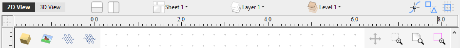
Above the view window is a handy toolbar that allows easier access to common tools. With the ability to create a double sided project you have easy access to switch between the Top and Bottom Sides of your project. The Layers, Sheet and Level Drop down bar have now moved from the tabs onthe left to the View Toolbar, making it accessible at all times. The other icons displayed in order of left to right are as follows
Tile 2D & 3D View Windows
 | Stack 2D and 3D View windows vertically |
 | Stack 2D and 3D View windows horizontally |
Visibility Options
 | Toggle component preview visibility |
 | Toggle bitmap visibility |
Toolpath Drawing Toggle
 | Toggle 2D Toolpath Drawing |
  | Toggle solid 2D Toolpath Drawing |
Drop Down Sections
 | Sheet drop down bar |
 | Layer drop down bar |
 | Level drop down bar |
Snapping Toggle Options
 | Snap to geometry |
 | Smart Snapping |
 | Snap to Grid |
View Controls
| Toggle Pan / Twiddle View |
| Zoom to box |
| Zoom to show all Drawing (Shift to Zoom to Drawing on Active Sheet) |
| Zoom to selection |
3D View Options
When working in the 3D view additional icons will appear on the View Toolbar.
Two-Sided Machining
When you are working on a two-sided job additional icons will appear on the View Toolbar. You will see an icon indicating whether the job you are working on will be flipped horizontally or vertically. This is important because the software will automatically mirror your toolpaths and geometry around different axes depending on this setting. To maintain the correct alignment of your toolpaths you must physically turn the material on your CNC machine in the same direction as you have specified during the design process.
The next icon indicates which side you are currently working on. This can also be clicked on to toggle between the single sided view or two sided view.
Note
The rulers that border the 2D View are colored to provide a handy visual indicator as to which side is currently active. An Orange background indicates that the Bottom side is currently active and any drawing or toolpaths are associated with the Bottom Side of your design.
Rotary Machining
When you are working on a rotary job an additional icon will appear. This button allows you to toggle the 3D view between wrapped display mode and flat display mode.

Vector Boundary
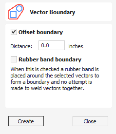
The Vector Boundary form allows you to create boundaries around selected vectors.
Watch this video to see this in action:
Offset Boundary
When this is checked ✓ the created boundary is offset outwards by the distance specified.
Rubber Band Boundary
When this is checked ✓ the created boundary is the result of stretching a rubber band around the currently selected vectors.
The images below demonstrate the difference between the two types of boundary that the form creates. The picture on the left illustrates the standard offset output and the one on the right shows the result when Rubber band boundary option is checked ✓.
Usable In Both Views
This tool can be used in both the 2D and 3D View.
2D View offers a more direct way to view your vectors while 3D Offers more flexability to work with Vectors in 3D Designs and to make use of the Edit Boxes.
Export Model as an STL File
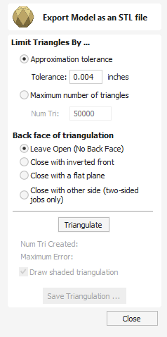
The STL file format is an industry standard for representing 3D models as meshes made up of a skin of triangles. It is a very robust way of exporting a version of your 3D composite model to external applications or even Rapid Prototype (RP) machines. Models can also be exported as an OBJ file, which includes the component colors and is primarily used for ray-traced rendering of your model.
Watch this video to see this in action:
Limit Triangles By...
In general, triangle meshes are not able to hold as much detail as Aspire's 3D Components. As a result, you must choose which strategy Aspire will use to reduce the detail in your STL file.
Note
When exporting the rotary model, currently there is no control over the number of triangles and the mesh will be exported at the highest quality. That means that the generated file will have a considerable size.
Approximate tolerance
Using this option the quality of the mesh is defined by how closely you allow the software to approximate the model. The smaller the number the better the detail and smoothness of the model but the larger the memory size of the file will be.
Maximum number of triangles
Using this option the quality of the mesh is limited by how many triangles you specify here, the larger the number the better the detail and smoothness but the larger the memory size of the file will be.
Back face of triangulation
The Composite model does not have a defined back face, because it is generally unnecessary for conventional 3-axis CNC machining. When converting your composite model to a 3D mesh, however, it can be useful to form a closed mesh by creating a back face automatically.
Leave Open (No Back Face)
This creates a mesh with an open back. This creates a shell with the 3D shape on its face and an open back side.
Note
When exporting the rotary model this option will result in a mesh without caps at the ends.
Close with inverted front
This creates a mesh with a copy of the front of the model on the back. This is used when a solid 2 sided model is needed for output. An example of this might be a 2 sided fish.
Note
When exporting the rotary model this option is not available.
Close with a flat plane
This creates a mesh that has its back sealed off with a flat plane. This type of closed model may be required by Rapid Prototyping (3D Printing Software) to allow the part to be prepared for the production process.
Note
When exporting the rotary model this option is not available.
Close with other side (two-sided jobs only)
In the case of two-sided jobs, this option can be selected. It will triangulate both sides of a job and produce a single closed mesh.
Note
When exporting the rotary model this option is not available.
Close sides
This option is only available for rotary jobs. When it is selected the created mesh will have caps on the ends.
Triangulate
When the options for the mesh have been selected then clicking will actually calculate the mesh and display the result in the 3D View. If this does not look correct (such as not being detailed enough) then the options can be changed and this button clicked again to re-calculate the mesh.
Num Tri Created
Once a mesh has been created, this field reports how many triangles it comprises. The more triangles are used, the larger the file size and the more difficulty external applications may have in manipulating them.
Maximum Error
This field indicates the worst deviation of a mesh triangle from the original 3D model.
Draw shaded triangulation
The triangle mesh can be viewed in wireframe or shaded modes using this option.
Save Triangulation...
Once the mesh looks correct, then clicking this button enables it to be saved onto your computer as an STL format file by default. The file save dialog also allows the selection of Wavefront (*.obj) and POV-Ray Scene (*.POV) as an alternative triangle mesh format using the Save as type option.
Note
When saving an obj file, an additional material (*.mtl) file and texture image file (*.jpg) will also be created - all three files will be required when opening the obj file in a 3rd party modelling or rendering package.
Create Cross Section Vector
With this tool active, select 2 points across a 3D model to create a Vector of the 3D Components Cross Section.
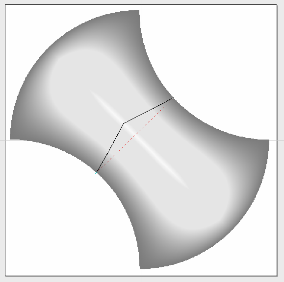
Seen here is the Dashed Pink Cross Section Tool Line dragged over the 3D Component and the resulting Vector generated from it.
Watch this video to see this in action:
VCarve Inlay Toolpath - Pocket
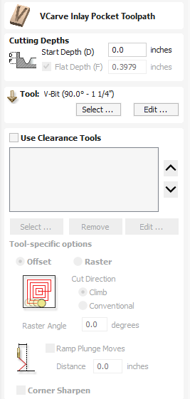
The VCarve Inlay Pocket Form is used to make adjustments to the Pocket half of a VCarve Inlay you have created.
Start Depth (D)
When Editing the Pocket part of a VCarve Inlay, you will be able to adjust the Start Depth (D) of the toolpath.
This will allow you to drop the Inlay toolpath into an existing Pocket you have cut in the project.
This can help if you are looking to add the Inlay into the bottom of a Bowl you have made for example.
Flat Depth (F)
This is fixed by the original VCarve Inlay Generation and is directly related to the Plug side of the toolpath.
If this requires altering, please delete both the Pocket and Plug toolpaths you have generated and remake them.
Use Clearance Tools
You can add a large area clearance tool here to help remove material more efficiently from the VCarve Inlay Pocket, if you have not already included one in the original toolpath generation.
Migrating Post-Processor POST_BASE
Prior to V11.0, we had the POST_BASE global variable as a way alleviating some of the repetitions inherent to post-processors to make their management and organisation easier. This seemed to create trouble over the years, so we have stopped supporting it.
This guide will help migrate from some of the old post-processors.
Default Post-Processors
If you have not made any changes to your post-processor, you could find it again in the Vectric shipped database in the Post-Processor Management dialog and simply click 'Customise' to add it again to your My_PostP folder.
For the purpose of this guide, we will demonstrate this on the Next Wave post-processor, but the guidelines here can be applied to any post-processors.
The base does not need to change
In this guide, we will go through how to replace the POST_BASE statement. We will never have to alter the base post-processor (referenced in that statement), but only the post-processor containing that statement. Please always back up your file first.
Check your output
Save some toolpaths using this new post and check the output!
What is a Base Post
In previous versions of the software then it was possible for a post-processor to have a base post-processor. The base post-processor had common sections in it. Then any other post-processor could take this post-processor as it's starting point, overwriting the bits it needed to. In this case we would say that this new post-processor inherited the base post-processor.
Summary of Migration
Assuming a post-processor Next_Wave_CNC_mm.pp which inherits the Next_Wave_CNC.pp post-processors:
The syntax of a typical POST_BASE statement is POST_BASE = "Next_Wave_CNC.pp"
Since this is no longer supported, we would need to replace this statement with the contents of Next_Wave_CNC.pp, removing any duplication from the copied content.
Step-by-Step Example
Again, assuming the Next Wave post-processors
Next_Wave_CNC.pp
We have Next_Wave_CNC.pp (inch post-processor) with the content containing the following,
POST_NAME = "Next Wave CNC (inch)(*.tap)"
FILE_EXTENSION = "tap"UNITS = "INCHES"DIRECT_OUTPUT = ""SUBSTITUTE = "({)}"LASER_SUPPORT = "YES"+------------------------------------------------
+ Line terminating characters
+------------------------------------------------LINE_ENDING = "[13][10]"+------------------------------------------------
+ Block numbering
+------------------------------------------------LINE_NUMBER_START = 0
LINE_NUMBER_INCREMENT = 10
LINE_NUMBER_MAXIMUM = 999999+================================================
+
+ Formating for variables
+
+================================================VAR LINE_NUMBER = [N|A|N|1.0]
VAR POWER = [P|A| S|1.0|10]
VAR SPINDLE_SPEED = [S|A|S|1.0]
VAR CUT_RATE = [FC|A|F|1.1]
VAR PLUNGE_RATE = [FP|A|F|1.1]
VAR X_POSITION = [X|A| X|1.4]
VAR Y_POSITION = [Y|A| Y|1.4]
VAR Z_POSITION = [Z|A| Z|1.4]
VAR ARC_CENTRE_I_INC_POSITION = [I|A| I|1.4]
VAR ARC_CENTRE_J_INC_POSITION = [J|A| J|1.4]
VAR X_HOME_POSITION = [XH|A| X|1.4]
VAR Y_HOME_POSITION = [YH|A| Y|1.4]
VAR Z_HOME_POSITION = [ZH|A| Z|1.4]
VAR DWELL_TIME = [DWELL|A|P|1.2]
+================================================
+
+ Block definitions for toolpath output
+
+================================================+---------------------------------------------------
+ Commands output at the start of the file
+---------------------------------------------------begin HEADER"( [TP_FILENAME] )"
"( File created: [DATE] - [TIME])"
"( for Next Wave Automation from Vectric )"
"( Material Size)"
"( X= [XLENGTH], Y= [YLENGTH], Z= [ZLENGTH])"
"( Z Origin for Material = [Z_ORIGIN])"
"( XY Origin for Material = [XY_ORIGIN])"
"( XY Origin Position = X:[X_ORIGIN_POS], Y:[Y_ORIGIN_POS])"
"( Home Position)"
"( X = [XH] Y = [YH] Z = [ZH])"
"( Safe Z = [SAFEZ])"
"([FILE_NOTES])"
"(Toolpaths used in this file:)"
"([TOOLPATHS_OUTPUT])"
"(Tool used in this file: )"
"([TOOLS_USED])"
"([TOOLNAME])"
"(|---------------------------------------)"
"(| Toolpath:- '[TOOLPATH_NAME]' )"
"(|---------------------------------------)"
"G90"
"G20"
"[FC]"
Next_Wave_CNC_mm.pp
We also have Next_Wave_CNC_mm.pp which inherits it as
POST_NAME = "Next Wave CNC (mm)(*.tap)"
POST_BASE = "Next_Wave_CNC.pp"UNITS = "MM"LASER_SUPPORT = "YES"+================================================
+
+ Formating for variables
+
+================================================VAR LINE_NUMBER = [N|A|N|1.0]
VAR POWER = [P|A| S|1.0|10]
VAR SPINDLE_SPEED = [S|A|S|1.0]
VAR CUT_RATE = [FC|A|F|1.1]
VAR PLUNGE_RATE = [FP|A|F|1.1]
VAR X_POSITION = [X|A| X|1.3]
VAR Y_POSITION = [Y|A| Y|1.3]
VAR Z_POSITION = [Z|A| Z|1.3]
VAR ARC_CENTRE_I_INC_POSITION = [I|A| I|1.3]
VAR ARC_CENTRE_J_INC_POSITION = [J|A| J|1.3]
VAR X_HOME_POSITION = [XH|A| X|1.3]
VAR Y_HOME_POSITION = [YH|A| Y|1.3]
VAR Z_HOME_POSITION = [ZH|A| Z|1.3]
VAR DWELL_TIME = [DWELL|A|P|1.2]
+================================================
+
+ Block definitions for toolpath output
+
+================================================+---------------------------------------------------
+ Commands output at the start of the file
+---------------------------------------------------begin HEADER"( [TP_FILENAME] )"
"( File created: [DATE] - [TIME])"
"( for Next Wave Automation from Vectric )"
"( Material Size)"
"( X= [XLENGTH], Y= [YLENGTH], Z= [ZLENGTH])"
"( Z Origin for Material = [Z_ORIGIN])"
"( XY Origin for Material = [XY_ORIGIN])"
"( XY Origin Position = X:[X_ORIGIN_POS], Y:[Y_ORIGIN_POS])"
"( Home Position)"
"( X = [XH] Y = [YH] Z = [ZH])"
"( Safe Z = [SAFEZ])"
"([FILE_NOTES])"
"(Toolpaths used in this file:)"
"([TOOLPATHS_OUTPUT])"
"(Tool used in this file: )"
"([TOOLS_USED])"
"([TOOLNAME])"
"(|---------------------------------------)"
"(| Toolpath:- '[TOOLPATH_NAME]' )"
"(|---------------------------------------)"
"G90"
"G21"
"[FC]"
Changes Summary
We would like to change the contents of Next_Wave_CNC_mm.pp such that it does not have POST_BASE and does not depend on the content of Next_Wave_CNC.pp.
You will note that Next_Wave_CNC_mm.pp has changed the following,
POST_NAMEUNITSLASER_SUPPORT- Various variables
- The
HEADERsection
We have to ensure that those things are kept the same in the new Next_Wave_CNC_mm.pp.
Steps
This will serve as a rough set of steps on how to approach this.
- Create a new empty file (called Next_Wave_CNC_mm_2.pp, for example) and copy the contents of the Next_Wave_CNC.pp into it.
- Go through the old inheriting post-processor (Next_Wave_CNC_mm.pp) and copy / replace the variables and sections.
- For example, replace POST_NAME, UNITS and LASER_SUPPORT
The beginnings of the new post-processor should look something like this
POST_NAME = "Next Wave CNC (mm)(*.tap)"FILE_EXTENSION = "tap"UNITS = "MM"DIRECT_OUTPUT = ""SUBSTITUTE = "({)}"LASER_SUPPORT = "YES"Keep going and replace / add the variables (starting with VAR).
Replace the begin HEADER section.
Check the result
Diff the contents of Next_Wave_CNC.pp and Next_Wave_CNC_mm_2.pp and you should see that the differences are essentially the contents of Next_Wave_CNC_mm.pp.
Remove Next_Wave_CNC_mm.pp and rename Next_Wave_CNC_mm_2.pp to Next_Wave_CNC_mm.pp.
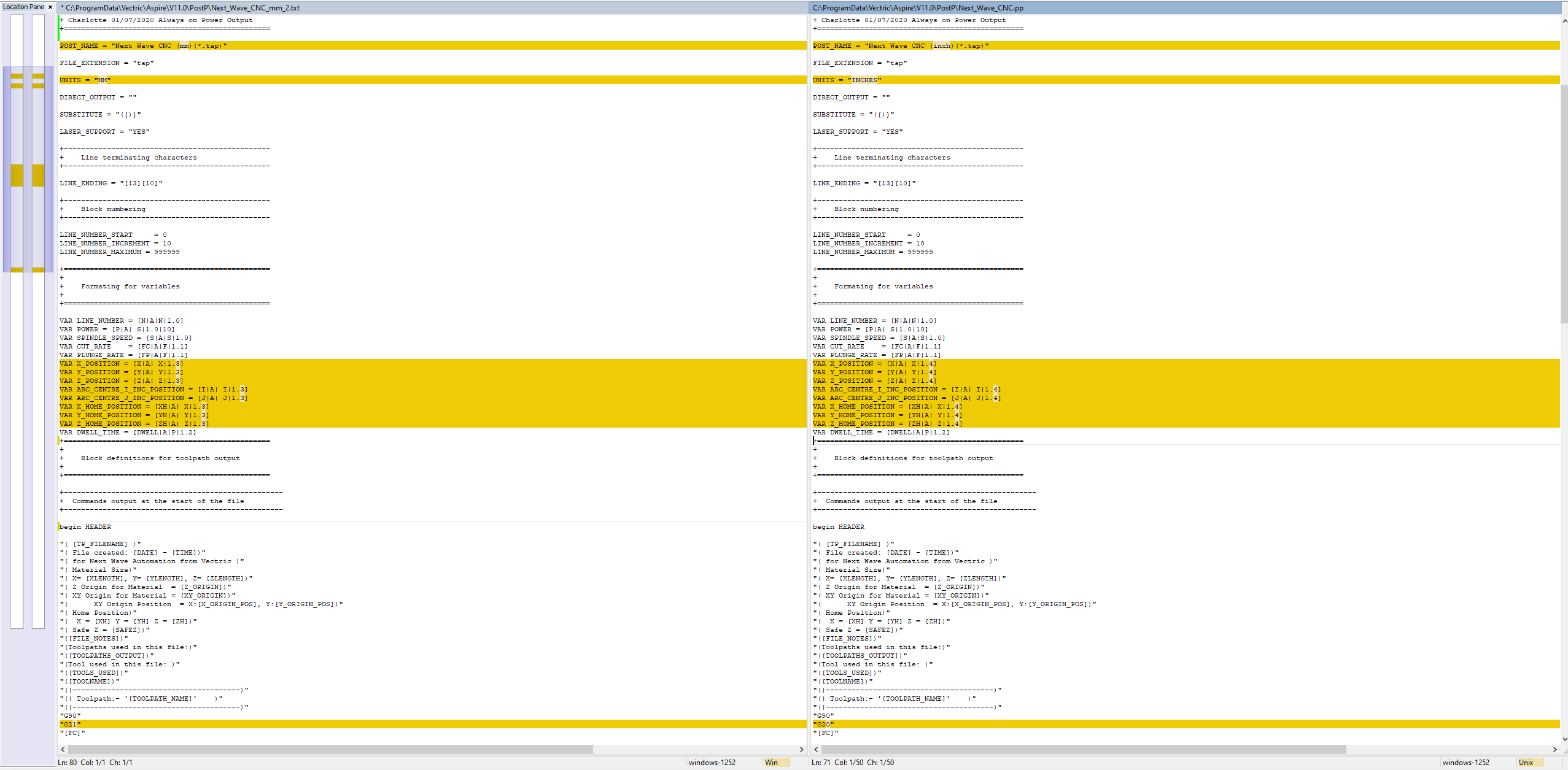
Check your output
Save some toolpaths using this new post and check the output!
05. Getting Started - Example Project
Cutting a Calibration Pattern
For our quick introduction we are going to us a 2D Profile toolpath strategy to engrave a precisely sized and aligned rectangle, circle and star. This pattern will use all the steps we have outlined in The CNC Workflow. It will also allow us to check that the CNC machine is working correctly using some simple but important features of the design:
- The rectangle, circle & star should not appear warped or distorted.
- The dimensions of the carved shapes should exactly match the design.
- The alignment points of the 3 shapes should not show any discrepancies.
- The star is rotated slightly clock-wise and the carving should match the original orientation of the design with no unexpected reflections in X or Y.
At the end of this guide we will review these checks and suggest some troubleshooting tips if any of them are not as they should be.
Material, Tooling & Hold-Down
The XY dimensions of the design will be 100mm (4") so you will need a piece of material approximately 150mm (6") square or larger.
The precise thickness of material is not too important as the design will simply be carved into its surface at a depth of 1.5mm (1/16"). Any piece that is 3mm (1/8") thick or greater will therefore be fine. An offcut of plywood or mdf board would be ideal.
To avoid any chance of collision with clamps or cutting into a screw, the best starting method to hold down a small piece of material like this is to use double sided tape. Any heavy duty 'carpet' type tape will work, but you may need to experiment to find a brand that secures well, but can also be cleanly removed once the job is complete.
The toolpth will be created based on a V-bit, but the precise tool angles are not important. If you don't have a V-bit tool, then a small (3mm, 1/8" diameter or less) end mill or ball nose tool will also work but the cuts will be the broader so the calibration pattern may be a little bit more difficult to interpret.
To avoid any chance of collision with clamps or cutting into a screw, the best starting method to hold down a small piece of material like this is to use double sided tape.
Create the Job
- Click `Create a new file` to get started.
This opens the `Job Setup` form. All projects start with a job setup. Here is where we consider the physical dimensions of our design. Note that you do not necessarily need to define the whole material block at this point, just that area needed for your design - the design area can be subsequently positioned anywhere on a larger physical material block using the `XY Datum Position`, which your CNC machine will use as its reference starting point.
Like all forms in the software, you should simply work from the top to the bottom of the `Job Setup` form. Forms are typically laid out with the most significant, non-optional or most commonly updated fields at the top. Sensible defaults are provided for most form fields the first time they are accessed (fields will generally remember their previous setting, once you edit them) so initially you can simply ignore any fields you are not sure about. At the bottom of most forms are the buttons to (accept), or any changes you have made.
- The job setup form allows for projects that will be cut from both sides or using a rotary axis, but for now we will simply select `Single Sided`.
We will set the `Job Size` units according to your preference.
Note that your CNC machine controller will be set to expect toolpaths defined in either metric or imperial units and you will need to refer to your CNC manufacturer to determine your particular setting - the Post-Processor you select later will need to match the toolpath to the controller's requirements but this is entirely independent of the units you prefer for designing within the software - everything will be automatically converted, if necessary, when the toolpath file is created.
- Set the width & height of your new job to both be 150mm (6")
- Set the
- Click OK
Design the Calibration Artwork
Your project needs to start with design drawing. On the left-hand side of the screen there are a number of tabbed panels that provide access to various tools to help you to draw your design.
In due course, we will use our design to begin creating toolpaths for our CNC machine. The functions relating to toolpaths and toolpath strategies are located in another panel on the right-hand side of the screen. Initially this panel is hidden. Once our design is largely complete we will switch our focus to the toolpath panel on the right.
This is the typical workflow when creating a CNC project and so the software interface makes this switching of focus easy and intuitive.
For now let's continue to focus on the tools available in left-hand design panel.
The first thing we will do is create a simple 100mm Square, using the Rectangle tool in the Design Panel on the left. Witht he Rectangle tool open, click into the 3D View to place a default rectangle, and in the Edit Boxes on the Right nd Bottom of the rectangle, click into each one and type 100.
This will create your Rectangle to be 100m x 100mm.
Now press the F9 key on the keyboard, and your Rectangle Vector will now be centered in your work space.
Create our First Toolpaths
Now that our design drawing is complete we are ready to consider what toolpath strategy we should use to cut this shape accurately and efficiently.
The software interface can automatically hide the design tools panel and show the toolpath strategy tools panel using the 'Switch to Toolpath commands' button.
- Click on the 'Switch to Toolpath commands' button at the top of the 'Design' tab.
The toolpaths tab will now open on the right-hand side of the software. Here you will find all the tools relating to the creation, editing and saving of toolpaths.
Selecting the most appropriate toolpath strategy for a particular job is one of the toughest aspects of initially learning how to use your CNC effectively. Over time you will explore the different strategies available within this tab and our extensive tutorials and practical examples will to understand what each is used for.
For now we are going to use just the first strategy availble under the Toolpaths Operations - this is the Profile Toolpath.
Click on the Profile Toolpath button to open the 2D Profile Toolpath form.
Saving and Loading the Project
At this point we should probably save our project. Saving the project document using the File->Save menu, or the Ctrl+S shortcut-keys, is just like saving any other conventional application document (i.e. Microsoft Word etc.) and it will include all of your 2D design elements, 3D models and toolpath strategy settings in a `*.crv` or `*.crv3d` file. This is the file that you can come back to any time at a later date to continue your work or to duplicate as the basis of a new project.
Note that this is *not* the file that your CNC machine will read. Saving Toolpaths (see below) is the indepenendent process by which you specifically save the file from this project that your CNC machine needs. It may be helpful to think of the toolpath saving process as more like creating PDF files *from* your Word document - PDF files aren't typically reloaded or edited but they are ready for 'printing'.
Previewing the Toolpath
Before we begin getting our toolpath files over to our CNC machine there is still a *very* important step for us to do in the software. We can preview exactly how our CNC machine will move and what the material should look like after each toolpath is completed using the Preview Toolpaths command.
Saving Toolpaths - Post Processing
You now need to Post Process your Toolpath to save your toolpath out into a file which your CNC Machine will be able to read.
In this guide we will assume that you have completed the "Machine Configuration" Process either Manually or using one of the existing Online Configurations as seen here.
With that step complete, you just need to now open the "Save Toolpath" form, using the bottom right most icon in the Toolpath Panels icons.
Make sure your machine is currently selected in the Machine
Running Your Toolpath
Every CNC machine and controller is different. At this point you will need to refer to your CNC machine manufacturers instructions for the details of running your toolpath file, but we can provide some generally applicable information about the typical process you should expect.
Secure your material
Your piece of material will need to be secured to the machine's bed. This is typically done by clamping, screwing or gluing your material down (larger or more sophisticated machines may have vacuum hold-down). In the first two cases you must be very careful to avoid cutting into your clamps or screws. As we noted in the Job Setup, the toolpath file does not have to be the same size as the material so the simplest way to avoid clamps and screws is to make sure your job dimensions (and thus your toolpaths) are no larger then the unobstructed area of your material and that it is correctly positioned within this region.
Set your origins (datums)
The movements of all toolpaths are relative to the `XY datum position` you selected when you initially created your job (in our example we set the bottom-left corner, but it can also commonly be the center of your design), these are also often referred to as "origins". Now you must indicate to your CNC machine controller where this datum point is physically located on your material. This process is usually referred to as "setting the XY datum", "setting the XY origin" or "zeroing X & Y".
In effect, setting the XY datum will position where your toolpath will be cut on your material.
You will also need to indicate to your controller how deep into the material your toolpath will cut - the equivalent of positioning your toolpath within the material. This is often known as "setting the Z origin", "setting Z zero" or "zeroing Z".
Again at this point it is important to know what `Z Zero Position` setting you used when you created your Job in the software - in our example we set it to be on the surface of the material, but in some circumstances it is useful to set it to the base of the material block, or your CNC machine's bed.
Because this job was created with the `Z Zero Position` to on the `Material Surface`, you will need to jog your CNC machine so that the tip of the tool is touching the surface of the material and then use its control software to zero the Z position.
Alternatively you may have an automatic Z touch plate or probe to achieve the same result - refer to your CNC manufacturer for instructions on this step.
Note: when wanting to do a test 'air cut' this is your opportunity to back your CNC machine upward in Z to a point in the air where the toolpath's maximum depth will not contact any physical material and set your Z zero 'in the air' instead. Running your toolpath with the Z origin in the air like this is a very useful test of movements of a toolpath if you have any doubts or uncertainties about your setup or toolpath settings before any real cutting.
At this point your CNC machine should be in a state where its position indicators would read X=0, Y=0 & Z=0 when the tip of the tool was at the position you defined when you created your origin job - in our example this would be at the bottom-left corner of the area we will cut and just touching the top surface of the material.
Load your toolpath File
Ready to go?
You should always consider a visual check of at least the initial start point and feedrates of an untested toolpath with an 'air cut' (see note above). Pay particular attention to the movement that will form the first full-depth, full-width cut - as this will be when the tool and CNC machine are under the most stress - to ensure that it looks appropriate for the tool and type of material you are intending to cut.
When you first start using your CNC it is worth considering keeping a simple written checklist at your controller. An example might be:
Have I:
- Run an 'air-cut' to check initial movement?
- Checked the material is firmly secured?
- Checked right type and shape of tool is fitted for this toolpath?
- Set the X,Y origin?
- Set the Z origin?
- Turned the spindle on (if not automatically enabled by your CNC machine's controller)?
OK, time to cut!
Always run any toolpath with untested or unverified tool settings with extra care and caution. When cutting with new tools and or in new materials seek advice from your CNC machine or tool manufacturer about the appropriate feeds and speeds for your machine and tooling.
Check the Calibration Cuts
Troubleshooting
Scale / units
My Design is cutting out much smaller/larger then it designed for.
Double check what distance your machine moves when you manually command the controller to jog from X=0 to X=1
The distance it travels should be exactly 1 Inch or 1mm.
If it moves the 1 Inch then you need to ensure that when you save your toolpaths from Aspire that you use the Inches Post Processor.
Likewise, if it moves 1mm, then use the MM Post Processor instead.
If it moves a different distance, instead of one of these options, then the machine calibration needs to be reviewed with help from the machines supplier.
Double check this on each of the X Y and Z Axis's, and it must move the exact same distance on all Axis.
Backlash
Backlash is a physical issue in the machine where an Axis will move the correct distance for a cut, but then loosness on the Axis motor or screw barings will allow it to slip.
This can build up over time for the machine to graducally become more and more misaligned over the duration of a toolpath. Commonly if you see inaccuracy in cuts only in one direction then it will be backlash issues on that one Axis.
Report the issue to your machiine supplier for advice on how to elliminate backlash in your hardware.
Inverted axis
The most common indicator of an inverted axis is text being mirrored in a single direction. A rarer case can be when the router will raise when it should plunge, resulting in it cutting air, even when Z Zero is correctly set. This can be due to a number of factors, such as:
- Hardware Wiring.
- Controller Setup.
- Post Processor setup.
The Hardware wiring is always the first thing to check in these cases, to ensure that the machines hardware is all connected as intended, and there are no wiring issues. If the positive and negative terminals on a motor are reversed then the motor can go in reverse.
The controller setup is part of the controllers calibration, and if values are reversed here, it can cause the motors to then work in reverse.
Post Processor setup can sometimes require the reversing of an Axis. This will have been required by the machine supplier to fit their machines configuration. The Post Processor should usually not be reversed manually, and is setup to fit the machine suppliers specifications. In rare cases where it is needed to be changed to suit a CNC machines which cannot be corrected with the above points then Editing the Post Processor can help.
Emboss Component
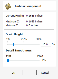
Embossing a component can be used in some cases to reduce the height of a model while preserving important surface detail as an alternative to the standard method for scaling a components height using the Shape Height option on the Component Properties form. A component must be selected before the tool can be used.
The images below show the same model, both results are scaled to ten percent of their original heights. The image below left was created using the standard Shape Height scaling from the Component Properties form and the image below right using the Emboss function.
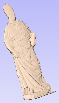
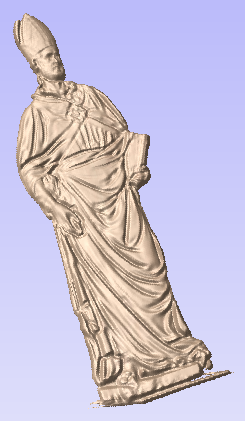
Scale Height
Use the Scale Height slider to adjust the final height of the component.
Detail Smoothness
Since the results of the initial detail scaling can be noisy the Detail Smoothness slider can be interactively adjusted to improve the visual quality of the result. In general, the greater the Scale Height the more Detail Smoothing needs to be applied.
Remarks
The Emboss tool is a very powerful feature but will not provide ideal results on every type of 3D model. Although it's possible to use the Emboss tool on models created in Aspire and other low-relief imported designs (such as the clipart), it's important to understand its intended use is with data from imported, full 3D (high relief) models and typically the best results will be obtained with this type of data.
Toolpath Templates
Toolpath templates allow you to improve the efficiency of your production processes by saving the complete toolpath settings for common operations. These settings can then be re-used at any time on different design geometry. Frequently used strategies and tooling can thus be applied to similar jobs, quickly and easily.
The operations you can do with templates include Loading toolpaths from templates, Saving a toolpath to a template and Saving all visible toolpaths to a template.
Create Shape - Angled
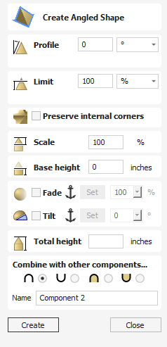
The Create Angled Shape tool creates a angled 3D model component.
Watch this video to see this in action:
Profile
The Profile setting will define the angle of the edge of the angled profile shape - the higher the angle, the steeper the shape.
Limit
This will limit the height of the shape created. This can be entered in as a value or you can use the slider bar in the drop down menu.
Preserve Internal Corners
When creating a shape using both external and internal vectors, the resulting component will have both external and internal corners. In this scenario, with this option unchecked the internal sides of the resulting shape would curve into the centre line at which the two sides meet if you draw a straight line from the top peak of the corner to the base of the shape, creating rounded internal corners.
Enabling this option by checking the box will mean that these internal sides will be comprised of a completely straight sided skeleton until both sides converge at the centre line of the corner, creating a defined sharp crease and an internal corner which will come to a sharp point as if the corners have been perfectly mitred.
Note
A good way to visualise the effect of this is to imagine looking at a corner of a building where two separate wings with pitched roofs meet, you’d expect to see a straight faced slope rather than a bowed slopein the corner from the ridge to the eaves. With this option deselected the slope would be pinched and curved inwards towards a single point in the corner.
This is best demonstrated with examples that use a polygonal base vectors;
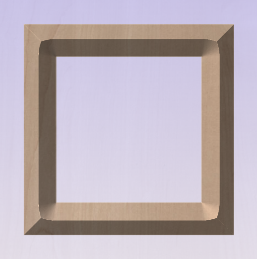
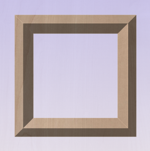
Scale
This limits the height of the shape by scaling the shape up or down while retaining its general specified profile. It is scaled to the height entered in the Height area of the form which becomes available once this option is selected. The slider can also be used to change the final height.
Base Height
Specifies the height of a flat 'base plane' added below the profile you have chosen.
Fade
When this option is checked ✓ the user can fade the Z depth of the Component. The first part of this operation (once the option is checked ✓) is to select the Set Anchor button - then click two points in the 3D view. The first click specifies the point which will remain at the current height. The second click specifies the point that the Component will be faded down toward. The shape will fade down from the first point to the second by the percentage selected.
Change the strength of the fade by clicking the down arrow next to the percentage value and using the slider to move this up and down or type in a specific value for the amount you would like to reduce the depth by. The fade will be applied linearly between the two selected points. This is a useful tool for giving the effect of a Component fading into the distance to help with overlapping areas of Components if you want to lower an area to give it the appearance of going behind another one.
Tilt
When this option is checked ✓ the user can set a direction and angle to tilt the shape up at an angle in Z. The first part of this operation (once the option is checked ✓) is to press the Set Anchor button - then click two points in the 3D view.
The first click specifies the point which will remain at zero (the pivot point of the tilt).
The second click specifies the point that will be tilted upwards by the specified angle (the point that will be raised up).
The angle can be edited by clicking the arrow next to the value and using the slider or by typing in a specific value and hitting the Space Bar on the keyboard to apply the angle.
Total Height
This is the Total height of the model and this will change when editing the Profile, Limit, Scale or Base Height options.
If you edit the height this will also edit the value in the Scale and Base Height section to create the shape at the correct height entered.
Combine with other component
This section includes options to allow you to name your Component and control the way it will be combined with other objects in the Component Tree.
Toolpath Tree
The Toolpath Tree is located at the bottom of the Toolpath Tab below the Operations section (toggle tab visibility using Shortcut key F12).
This area displays in a tree , the name of each calculated toolpath with a check-box to turn the visibility of the toolpath in the 3D View on and off. The icon next to the check-box shows the type of tool selected for that particular toolpath.
Double-Clicking the name of any of the toolpaths will open up the toolpath strategy window for that toolpath and allow edits to be made to it.
Right-Clicking on the toolpath shows a menu which is described in more detail in the Right Click Menus Page.
Sheets Filter
The Sheets Filter, located just above the toolpath tree itself, allows you to filter the toolpaths by sheet.
- Selecting a particular sheet from this drop down list will make that sheet active and the tree will only show the toolpaths associated with that sheet.
- If you select All Sheets from the drop down list the tree will display all toolpaths on all sheets. In this view, those toolpaths associated with inactive sheets will be displayed faded out, although all operations can still be performed on them.
Toolpath Groups & Sheets
Toolpath groups are not associated with any sheet and so will be shown in all circumstances.
Up and Down Arrows
The up and down arrow buttons to the right of the window allow the user to move the selected toolpath up and down in the list.
This will affect the order the Toolpaths are previewed in and if multiple toolpaths are saved as a single file, then this will be the order that the machine cuts them in.
Resizing
You can adjust the space available for the Toolpath list by clicking and dragging the divider that separates the Toolpath List from the Toolpath Operations section, up or down.
Two-Sided Job
The toolpath list shows the list of toolpaths on the current side only. The label at the top will change to indicate whether you're viewing the Top / Bottom sides. To view the toolpaths on the opposite side, just switch sides from the View Toolbar.
Toolpath Groups
It is possible to add groups into the toolpath tree to help with toolpath organization.
Adding a group
There are two ways to add a Toolpath Group:
- Right click on an empty space in the toolpath tree and click
- Or, right click and choose . This will take of the visible toolpaths and group them together.
Remove a Group
You can delete a toolpath group as you usually would delete any toolpath. Either via the right-click menu, or with the delete key. However when you delete a toolpath group then you will be asked if you want to keep the sub toolpaths or also have them deleted.
Add Toolpaths to a Group
You can move toolpaths in and out of groups by dragging them in the toolpath tree.
Model
Menu
| Create Component ► |
| Create Component From... ► |
 | |
 | |

| |
| Export as Grayscale Bitmap |
| Export as 3D Clipart: Exports the selected model as a .3DClip file. |

| |
 | |

| Reset Inside Selected Vectors: Deletes everything in the Working Model contained inside the selected vector(s) |

| Reset Outside Selected Vectors: Deletes everything in the Working Model contained outside the selected vector(s) |

| Split Selected Component: Split the currently selected component using a vector. |
 | Create Vector Boundary Around Selected Components: Creates a new vector that matches the edge of the selected component. |

| |

| |
 | |

| |
|
Create Component

| |

| |
 | |
 | |
 | Add Zero Plane: Creates a component that is the size of your job setup with a height of Zero. |
Create Component From...
 | |
 | |
 | |
 | |
 | |
| Create Component from Toolpath Preview |
Export As Grayscale Bitmap
This is export option will save the Composite Model (Working Model + visible Components) as a raster based image file (.bmp/.jpg/.gif format). This is mainly intended for users of Laser engraving equipment and CarveWright/CompuCarve machines. It could also be used to export the 3D as a grayscale for use with graphics programs.
When the image is exported the highest areas in the model will be white and the lowest will be black, all the other depths in between will be assigned graduated levels of gray depending on their relative position between the top and bottom of the part.


To use this function you must have either visible Components or something in the Working Model.
Create Component from Toolpath Preview
This will take the current Toolpath Preview and create a Component model from it. There are two main applications for this feature:
- It can be useful for helping to identify areas which have not been machined so a smaller tool can be used to carve them with more detail.
- It can be used to create model Components where some of the shape has been created using the tool shape such as fluted veins on a leaf or a texture toolpath]. This second application would be particularly beneficial for customers who plan to save a grayscale image of the 3D model (for Laser or CarveWright) rather than running the actual toolpaths from the software.
Once this is selected the current Toolpath Preview will be converted into a Component. This is then added to the Component List and will be called Toolpath Preview.
If the part has been cut-out and the Delete Waste Material option has been used then just the parts left on the screen will become the Component. If the part is not fully cut-out or the waste material has not been deleted then the whole Toolpath Preview block will become the Component, including what may be scrap material. It is possible to avoid this even without deleting the waste by using the Shift key - see below for more information.
By holding down either the Ctrl or Shift key, there are two options that can be activated when the Create Component from Toolpath Preview feature is selected.
If you press the Shift key when you create the Component, the areas of the Toolpath Preview over transparent areas in the composite model will be discarded. This will give you a Component that represents the Toolpath Preview but deletes anything that is not within the area of the 3D model the toolpaths were created on in the first place.
If you press the Ctrl key, the Component created will represent the difference between the composite model and the Toolpath Preview. The model this creates will look odd as it will just represent the material that was left by the radius of the tool on the finish cut. This can be useful if you want to machine those areas with a smaller tool as this model may then be used to create the vectors to limit the toolpath for that operation, minimizing the time to create a more detailed finish.
The images below show the 3 options available. Below left is the standard Component created from a machined model which includes the waste block. The middle option shows the option when the Shift key is pressed which discards the Preview model outside of the original area of the machined part. Finally the right hand image shows the Component which is created when holding the Ctrl key down which is the different between the original part and the Middle image.
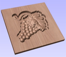
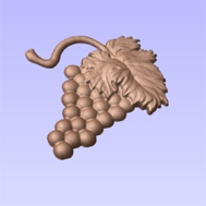
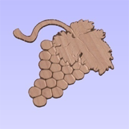
IMPORTANT NOTE
Although this option can be selected at any time, it only makes sense to use this feature while the Toolpath Preview is active in the 3D View, this will ensure that the Component represents what can actually be seen. The Toolpath Preview can be accessed using the icon in the Toolpath Operations menu (shown below highlighted with a red box), this will also appear automatically after the calculation of any toolpath.
Create Shape - Custom
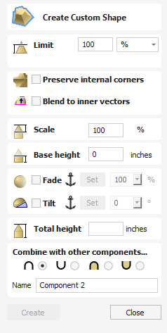
The custom shape profile uses a vector to define the profile rather than using one of the standard profiles.
To use the custom profile option a selection of closed vectors, plus an additional open vector representing the profile, must be selected.
When using a custom profile, the form the final shape will take comes from considering the shape above the line joining the end points. For this reason the profile vector should usually have a leg.
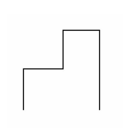
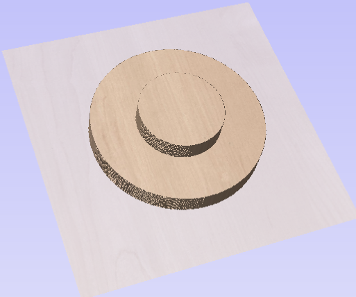
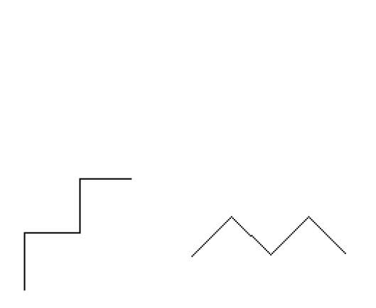
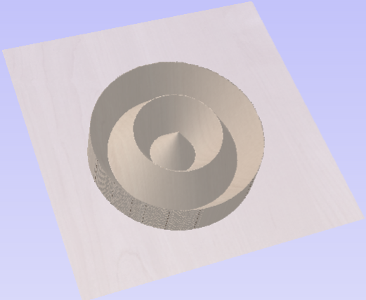
Watch this video to see this in action:
Limit
This will limit the height of the shape created. This can be entered in as a value or you can use the slider bar in the drop down menu.
Preserve Internal Corners
When creating a shape using both external and internal vectors, the resulting component will have both external and internal corners. In this scenario, with this option unchecked the internal sides of the resulting shape would curve into the centre line at which the two sides meet if you draw a straight line from the top peak of the corner to the base of the shape, creating rounded internal corners.
Enabling this option by checking the box will mean that these internal sides will be comprised of a completely straight sided skeleton until both sides converge at the centre line of the corner, creating a defined sharp crease and an internal corner which will come to a sharp point as if the corners have been perfectly mitred.
Note
A good way to visualise the effect of this is to imagine looking at a corner of a building where two separate wings with pitched roofs meet, you’d expect to see a straight faced slope rather than a bowed slopein the corner from the ridge to the eaves. With this option deselected the slope would be pinched and curved inwards towards a single point in the corner.
This is best demonstrated with examples that use a polygonal base vectors;
Blend To Inner Vectors
This option applies the selected profile across the selected vectors. It blends to the profile from the outside of the vectors to the inner vectors
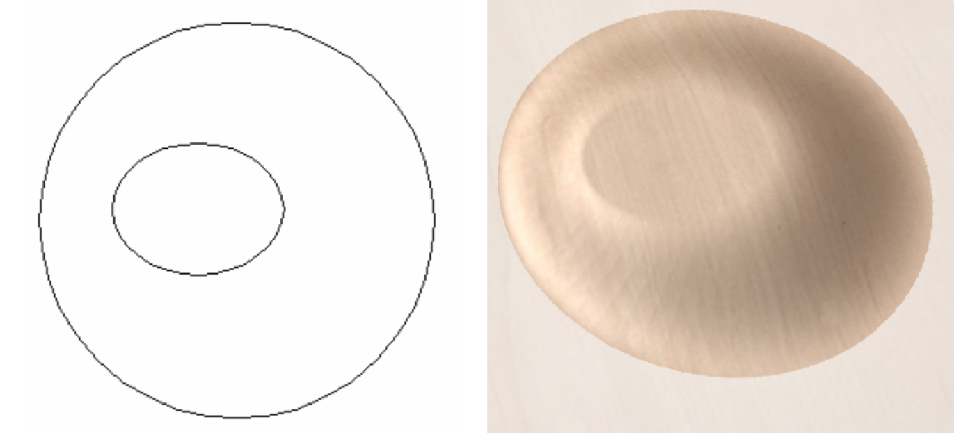
Scale
This limits the height of the shape by scaling the shape up or down while retaining its general specified profile. It is scaled to the height entered in the Height area of the form which becomes available once this option is selected. The slider can also be used to change the final height.
Base Height
Specifies the height of a flat 'base plane' added below the profile you have chosen.
Fade
When this option is checked ✓ the user can fade the Z depth of the Component. The first part of this operation (once the option is checked ✓) is to select the Set Anchor button - then click two points in the 3D view. The first click specifies the point which will remain at the current height. The second click specifies the point that the Component will be faded down toward. The shape will fade down from the first point to the second by the percentage selected.
Change the strength of the fade by clicking the down arrow next to the percentage value and using the slider to move this up and down or type in a specific value for the amount you would like to reduce the depth by. The fade will be applied linearly between the two selected points. This is a useful tool for giving the effect of a Component fading into the distance to help with overlapping areas of Components if you want to lower an area to give it the appearance of going behind another one.
Tilt
When this option is checked ✓ the user can set a direction and angle to tilt the shape up at an angle in Z. The first part of this operation (once the option is checked ✓) is to press the Set Anchor button - then click two points in the 3D view.
The first click specifies the point which will remain at zero (the pivot point of the tilt).
The second click specifies the point that will be tilted upwards by the specified angle (the point that will be raised up).
The angle can be edited by clicking the arrow next to the value and using the slider or by typing in a specific value and hitting the Space Bar on the keyboard to apply the angle.
Total Height
This is the Total height of the model and this will change when editing the Profile, Limit, Scale or Base Height options.
If you edit the height this will also edit the value in the Scale and Base Height section to create the shape at the correct height entered.
Combine with other component
This section includes options to allow you to name your Component and control the way it will be combined with other objects in the Component Tree.
Array Copy Toolpath
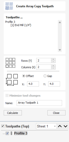
Using the same approach as the Array Copy Tool for vectors in your drawing, this toolpath operation allows you to duplicate one or more toolpaths into a grid of copies. One of the key benefits of this approach is that it allows you to subsequently edit your original toolpaths and the software will automatically update the associated array of copies.
Toolpath Selection
To use the Array Copy Toolpath, open the form and turn on the visibility for each of the toolpaths you wish to be part of your array using the visibility checkbox next to each toolpath in the list below the form. The current selected toolpaths appear in the Toolpaths list at the top of the form.
The position of the resulting grid of toolpaths is always created to the right and above the source toolpaths. Therfore, you should always position your source toolpaths in the bottom left corner of the area you wish the array to fill.
Rows and Columns
Use the Rows (Y) and Columns (X) boxes to specify the size of your grid and thus the total number of copies of the original toolpath(s) that will result.
Spacing
The spacing between the copies of the toolpath within the grid are controlled using the Offset and Gap radio button options. The X and Y edit boxes determine the offset between the start point of each toolpath or the spacing between the bounding boxes of the copy, depending on the radio button option selected.
Minimize Tool Changes
The final option, Minimize tool changes, will only be available if the source toolpaths are using different tools. This will group toolpaths with the same tool geometry across the copies so that they can be output together. By grouping in this way, the parts of each copy using the same tool are cut together and the entire array can be cut with the minimum number of tool changes. If this option is not set, then the toolpaths for each copy will be cut individually, with tool changes required for each. See the The Array Copy Toolpath Cut Sequence
Working with Array Copy Toolpaths in the Toolpath List
Array Copy Toolpaths are displayed in the Toolpath List in different way to other toolpaths. The source toolpaths (the ones originally selected as the basis of the array) are now shown below the array copy toolpath item in a tree structure. For complicated jobs you can hide the source toolpaths in the list using the small and controls next to the Array Copy Toolpath in the Toolpath List. The usual visibility checkboxes are also available for both the array copy toolpath and its source toolpaths.
You can rearrange the order of the source toolpaths within the array copy group either by dragging them up or down using the mouse, or by click the up and down ordering arrows at the top of the Toolpath List. These features give you total control of each toolpath type within the array and are particularly important for saving the toolpaths
Saving an Array Copy Toolpath
As far as possible, array copy toolpaths are saved in exactly the same way as other toolpaths except that each source toolpath in the list represents all of its copies. If you switch off the visibility of a source toolpath before saving, noneof the copied instances of that toolpath will be included in the saved toolpath. Thus you can use the visibility controls to save a toolpath that will cut all of the copies, but limited to a particular subset of the source toolpath types.
In general, the sequence of cutting will be to cut all of the included toolpath strategies for each copy in the grid before moving on to the next copy.
Important
If the array copy toolpath contains more than one source toolpath using the same tool, then the sequencing within the array copy toolpath as a whole can be affected by the Minimize tool changes option setting when it was first created.
Baking Components
In general, the most useful feature of individual Components is that they can be manipulated entirely independently of each other to build up simpler design elements into a sophisticated 3D model. There are some editing functions that require the individual element to be consolidated into a single object. For example you may wish to smooth one shape into another using the sculpting tools or bend a group of Components around a curve using the distortion tool. In Aspire, consolidating a selection of Components into a single, new object is a process called 'Baking'. Once baked, the selected Components will become a single Component object and you will no longer be able to access the individual elements.
Aspire will prompt you when you have a group or Component selection that requires baking before a particular modeling tool or operation can proceed. Alternatively, you can use the Bake command to perform this operation yourself. By manually baking-in existing fade, tilt or distortion, for example, you are then free to apply further dynamic properties 'on top of' the previously applied ones. In addition, consolidating multiple Components towards the end of the design process allows your computer to recover system resources and may give it a welcome performance boost - particularly if you have been modeling using a large number of high resolution or complex Components.
Copy
If you hold the Ctrl key down when you hit the Baking icon it will retain a copy of the original Components and create a new baked Component instead of replacing the original selection.
Fluting Toolpath
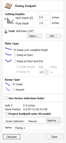
Fluting Toolpaths machine along vectors while varying the depth of the tool, creating extremely efficient machined decorative patterns.
This toolpath is similar to the option to Profile On a selected vector. The difference is the toolpath at the end of each vector can be ramped to taper the cut. This can be used for cutting standard woodworking Flutes or can be used for artistic engraving and marking effects with other types of artwork. In this section the options on the form will be covered along with some examples of the use for different applications.
Watch this video to see this in action:
Selecting Vectors
When the Fluting Toolpath form is open, the selected vectors will have their start points indicated in the 2D View by solid square green nodes, this is important as it will determine which end the ramps are added depending on what options are chosen on the form. An image of this is shown below where all the start points are to the left end of the selected vectors.
If you need to move the start points, go into node editing mode (press N on the keyboard or select the node editing icon in the Edit Vectors section on the left tab).
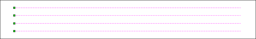
Select the vector you want to change the start point Move the cursor over the end you want to be the new start point Press P on the keyboard or Right Click and select Make Start Point from the pop-up menu. Exit node edit mode (press N again) Reselect all the vectors you want to flute
Cutting Depths
Start Depth (D)
This specifies the depth at which the Fluting toolpath is calculated. When cutting directly into the surface of a job the Start Depth will usually be 0. If machining into the bottom of an existing pocket or stepped region, the depth of the pocket/step that you are starting from must be entered.
Flute Depth
This is the depth of the Fluting toolpath relative to the Start Depth; the total depth will be the combination of the Start and Flute Depth.
Tool
Clicking the button opens the Tool Database from which the required tool can be selected. See the section on the Tool Database for more information on this. Clicking the button opens the Edit Tool form which allows the cutting parameters for the selected tool to be modified, without changing the master information in the database. Hovering the mouse cursor over the tool name will display a tool tip indicating where in the Tool Database the tool was selected from.
Flute Type
Ramp over complete length
Checking ✓ this option means the tool will ramp over the whole length of the toolpath. At the start of the selected vector/s it will be at the Start Depth and at the end of the selected vector/s it will have cut down to the Fluting Depth.
Ramp at Start
Checking ✓ this option means the tool will ramp down only at the start of the vectors to the Fluting Depth. The distance of this ramp can be specified using the Ramp Length or Ramp % options.
Ramp at Start and End
Checking ✓ this option means the tool will ramp down at the start of the vectors then will ramp up again at the end of the vectors. The distance of these ramps can be specified using the Ramp Length or Ramp % options.
Ramp Length
Checking ✓ this option means that the length of the ramp can be set to an exact distance entered into the box. The ramp distance is measured from the start and the end of the vector/s depending what Flute Type you have selected. If the distance entered is greater than the possible length of the ramp then the maximum length will be used, this would be the same as choosing Ramp over complete length. When you choose Ramp at Start it is possible to specify a ramp length which is up to the length of the vector/s. When Ramp at Start and End is checked, ✓ the maximum length possible would be half way along the vector/s as after that it would start to ramp up again.
Ramp %
Checking ✓ this option means that the length of the ramp can be specified as a percentage of the maximum possible ramp length (controlled by the length of the selected vector/s and chosen Flute Type). When you use this with Ramp at Start selected then 100% would be the whole length of the selected vector/s, the ramp length would be a percentage of this distance for each one. When you use this with Ramp at Start and End then 100% would be the half length of any of the selected vector/s. The ramp length would be a percentage of this half-length. In this situation using a 50% value would give you a Ramp from the start which was ¼ of the vector length and a ramp from the end which was also ¼ of the vector length.
Ramp Type
Linear
Selecting the Linear type will create a ramp which is a diagonal line (following the vector) from the Start Depth to the Flute Depth. Below you can see a Linear Ramp Type shown from the side. This ramp is set to only ramp from the start and to go 50% of the flute length.
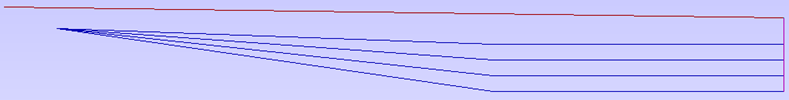
Smooth
Selecting the Smooth type will create a curved ramp (following the vector) from the Start Depth to the Flute Depth; this will smoothly transition from the ramp into the full depth of cut. You can see an example of this shown in the image below.
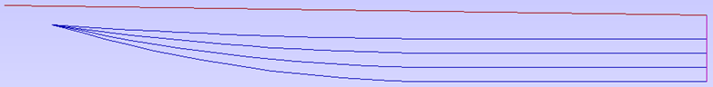
Position and Selection Properties
Safe Z
The height above the job at which it is safe to move the cutter at rapid / max feed rate. This dimension can be changed by opening the Material Setup form.
Home Position
Position from and to that the tool will travel before and after machining. This dimension can be changed by opening the Material Setup form.
Project toolpath onto 3D Model
This option is only available if a 3D model has been defined. If this option is checked, ✓ after the toolpath has been calculated, it will be projected (or 'dropped') down in Z onto the surface of the 3D model. The depth of the original toolpath below the surface of the material will be used as the projected depth below the surface of the model.
Note:
When a toolpath is projected onto the 3D model, its depth is limited so that it does not exceed the bottom of the material.
Vector Selection
This area of the toolpath page allows you to automatically select vectors to machine using the vector's properties or position. It is also the method by which you can create Toolpath Templates to re-use your toolpath settings on similar projects in the future. For more information, see the sections Vector Selector and Advanced Toolpath Templates.
Name
The name of the toolpath can be entered or the default name can be used.
Wrapped Fluting Layout
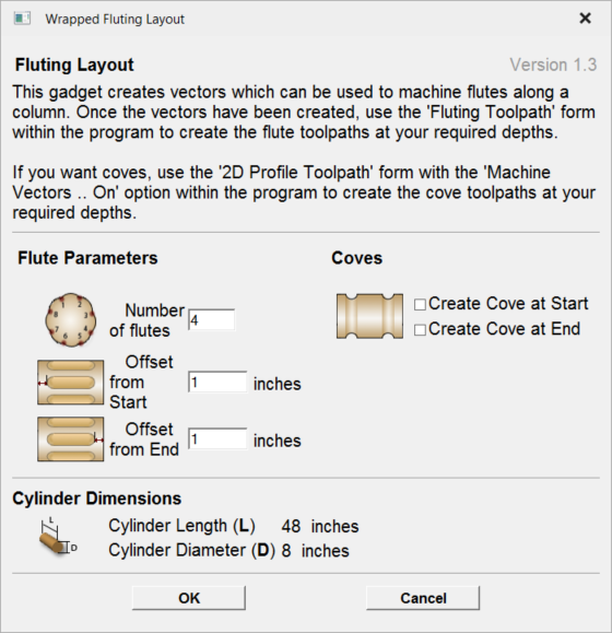
This gadget is used to simplify the task of creating toolpaths to machine flutes and coves on a rotary work piece. The gadget is designed to be used in a rotary job
This gadget does NOT create toolpaths directly. It lays out vectors in the 2D view which can then have toolpaths created using either the Profile or Fluting toolpaths within the main program. The top part of the form allows the user to specify how many flutes to create and how far from the start and end of the work piece the flute should start and end. Flutes are laid out evenly spaced based on the circumference of the cylinder. If the user chooses to create coves at either or both ends, extra vectors will be created which can be machined with the Profile toolpath and the Machine Vectors On option to create the coves.
The bottom section of the form contains details about the cylinder dimensions and is presented for reference only.
After the gadget has run the vectors required for machining will be visible in the 2D view. If you have a 3D form for your rotary piece, you can use the Project toolpath onto 3D model option on the toolpath forms to have your fluting toolpaths follow the work piece surface.
Fit Curves To Vectors
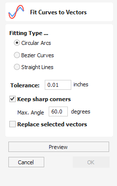
This function allows the user to fit arc, Bezier curves or straight lines to selected vectors. The newly created vectors will be approximated based on a user defined tolerance. Using this function can aid with smoothness for some toolpath options and also help to simplify data for modeling purposes.
Watch this video to see this in action:
Fitting Type
Circular Arcs
Checking ✓ this option means the selected vectors will be approximated using arcs:
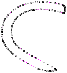
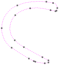
Bezier Curves
Checking ✓ this option means the selected vectors will be approximated using Bezier curves.
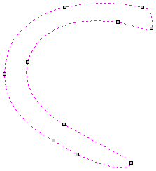
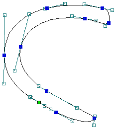
Straight Lines
Checking ✓ this option means the selected vectors will be approximated using straight lines.
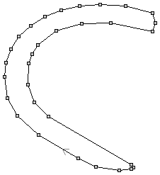
Tolerance
The value which is set in the Tolerance area determines how closely the original vectors will be approximated. The newly created, Arcs, Beziers or Lines will be generated within a distance of the original vector which is plus or minus the specified Tolerance value. The smaller the value the closer to the original the new data will be but it will also mean more data points will be used. A larger Tolerance will not be as accurate to the original but will have less data points.
Keep Sharp Corners
Checking ✓ this option will make the Curve Fitting routine keep sharp corners which have a difference greater than the Max Angle value specified. Any corners where the difference in angle is less than this value will be modified within the specified tolerance.
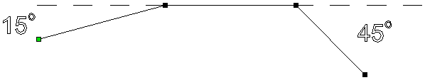
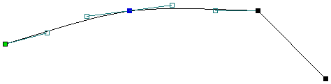
Replace selected vectors
Checking ✓ this option will delete the current vectors and replace them with the new curve fitted vectors. Un-checking it will keep the original vectors as is and in addition create new curve fitted vectors. The new vectors will always be created on the currently selected Layer.
Usable In Both Views
This tool can be used in both the 2D and 3D View.
2D View offers a more direct way to view your vectors while 3D Offers more flexability to work with Vectors in 3D Designs and to make use of the Edit Boxes.
General Workflow
Aspire has been developed to allow the production of decorative and artistic dimensional carved parts. As well as drawing and modeling tools, it includes both 2D and 3D machining, along with 3D V-Carving / 3D Engraving to allow a huge variety of jobs to be produced as quickly and easily as possible.
Workflow Logic
- Layout 2D Design:
- Import Vectors
- Draw Vectors
- Import Bitmaps
- Create 3D Components:
- Create shapes from 2D design vectors
- Create (texture) shapes driectly from bitmaps
- Import 3D Clipart and models from other CAD systems
- Manipulate 3D components to create the 3D composite model using the component tree:
- Change location, depth, size, angle etc.
- Group and change relationship to other components
- Create 2D, 2.5D or 3D toolpath:
- Create or edit vector boundaries for toolpaths
- Specify tool details for each strategy
- Preview Final Part:
- Visualize the part as it will actually look.
- Create proof images for customer.
- Check estimate for cutting time
- Save the CNC Code: Save the final cut file to send to the CNC machine
Design
Aspire includes drawing and editing tools that allow designs to be created and modified. Functions for vector creation and editing are very easy to use and multiple design elements can also be drawn or imported, scaled, positioned and interactively edited to make a new design. Text can also be created using any TrueType or OpenType fonts installed on your computer, or the single stroke engraving fonts supplied with the software.
Model
Once the 2D design is ready, 3D components can be created from 2D Vector drawings. This will probably involve adding and changing 2D artwork a bit as the 3D design evolves, so Aspire's interface makes the drawing and modeling tools easily accessible.
In addition, existing 3D models can be imported to be incorporated into a design, these could be files previously created in Aspire, 3D Clipart that has been purchased and downloaded or models from other CAD design systems in a supported format.
Toolpath
A comprehensive set of 2D, V-Carving, Engraving and 3D toolpath strategies provide you with efficient ways to use your tooling to carve the finished part. This process is usually relatively independent of drawing or modeling (although toolpaths are often created directly from some artwork or 3D composite models). Aspire provides simple interface buttons to toggle screen layout to assist the shift in focus from design to toolpathing.
Output
Finally you can use Aspire's large selection of post-processors to save toolpaths in precisely the format that your particular CNC machine tool requires.
Signing In
Signing into the software gives users more benefits when it comes to your tool database backups and licence updates.
How to Sign In
You can sign in using different methods,
- Through the Licence Dialog as a more convenient method for entering your licence details.
- Through the button at the top right bar.
- In the Tool Database dialog to be able to back up and retrieve your database.
- In the Clipart Tab to be able to access your free clipart more conveniently.
Vector Texture
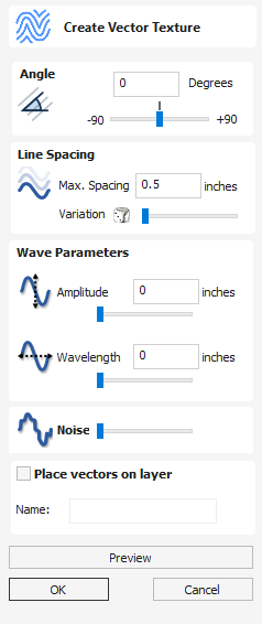
Repeating texture patterns can be created using the Create Vector Texture tool. These vectors can be machined in a variety of ways to create attractive textures.
To use the tool click the icon on the drawing tab. If required, select any contours that you wish the pattern to be created within. By using the sliders and edit boxes on the form the style of the created pattern can be varied. Click Preview to see a preview your created texture as you adjust the form's parameters. When you are happy with the preview, click OK to create the pattern.
Watch this video to see this in action:
Angle
The lines in the texture are created at an angle. This value can be set to any value between -90 degrees and 90 degree.

Line Spacing
The line spacing controls the distance between the contours created by the tool. Use the edit box labeled Max. Spacing to enter a maximum value of line spacing. The slider underneath the edit box controls the degree of variation in the line spacing. If the slider is to the far left then this mean variation is at a minimum and so the lines are evenly spaced. If the slider is to the far right the variation is highest and so the distance between created contours varies between zero and the maximum spacing specified.
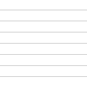

Wave Parameters
Within this section of the form the created pattern can be made to behave in a wave-like fashion. This wave is controlled by two parameters: the amplitude and wavelength.
Wavelength
The wavelength describes the length over which the contours shape repeats itself. A bigger wavelength gives a long wave while a small wavelength gives a short wave.
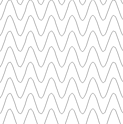
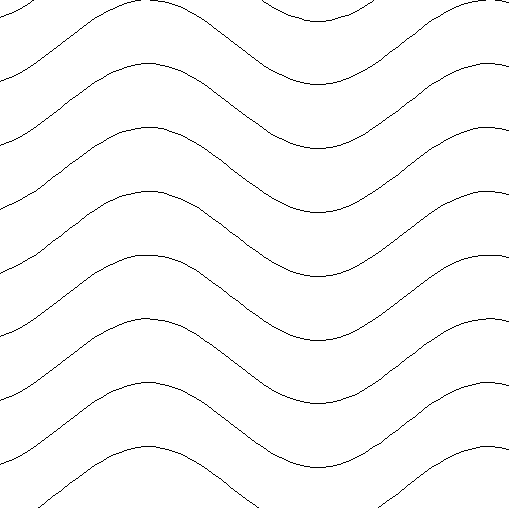
Amplitude
The amplitude describes the height of the wave. Larger amplitude means a taller wave and smaller amplitude means a shallow wave.
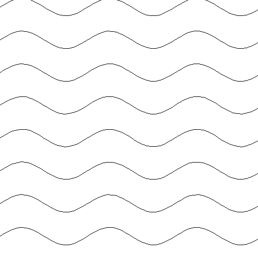
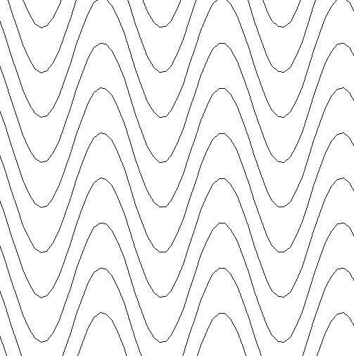
Noise
The noise slider controls the degree of randomness applied to the above values and can be used to create less regular patterns.
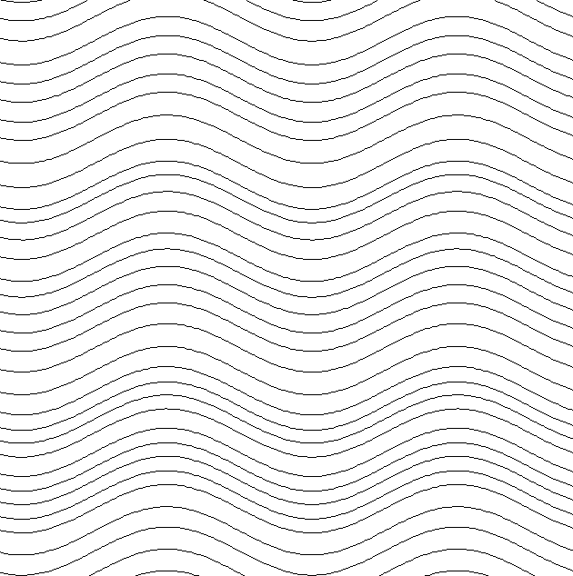
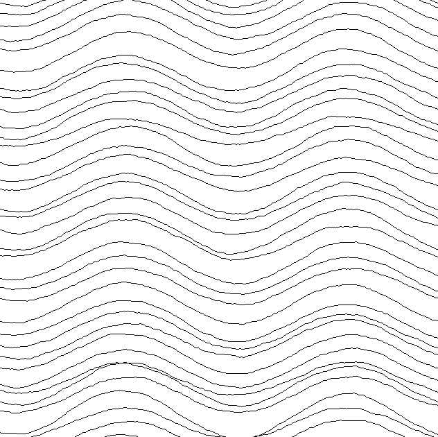
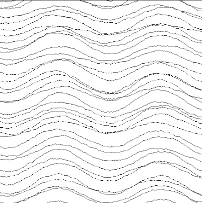
Vector Layer
To create the vectors on a new layer make sure the check box labeled Place Vectors on Layer is checked ✓ and enter the layer name into the edit box labeled Name.
Job Setup Form
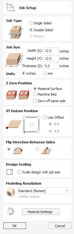
The Job Setup form is displayed whenever a new job is being created, or when the size and position of an existing job is edited. It allows to create following types of job:
Job Setup - Rotary
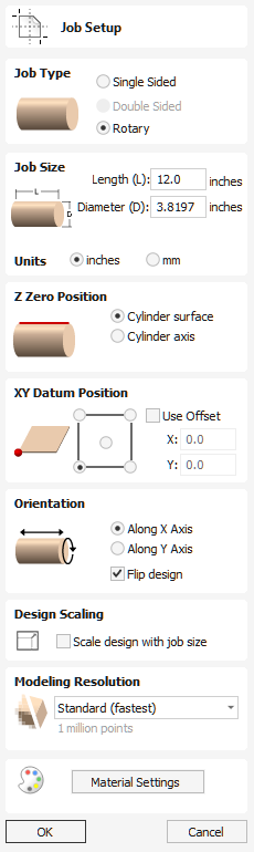
The Job Setup form is displayed whenever a new job is being created, or when the size and position of an existing job is edited.
In most cases a new job represents the size of the material the job will be machined into or at least an area of a larger piece of material which will contain the part which is going to be cut. Clicking OK creates a new empty job, which is drawn as a gray rectangle in the 2D View. Dotted horizontal and vertical Grey lines are drawn in the 2D design window to show where the X0 and Y0 point is positioned.
Check out this video for a short introduction to Rotary Machining:
Job Size
Length
Length of the material
Diameter
Diameter of the material
Units
Whether the job units are measured in mm or inches
Z Zero Position
Indicates whether the tip of the tool is set off the rotation axis (as shown in the diagram) or off the surface of material for Z = 0.0. For the best accuracy using Cylinder Axis option is recommended
XY Datum Position
This datum can be set at any corner, or the middle of the job. This represents the location, relative to your design, that will match the machine tool when it is positioned at X0, Y0. While this form is open, a red square is drawn in the 2d view to highlight the datum's position.
Use Offset
This option allows the datum position to be set to a value other than X0, Y0.
Orientation
This option selects along which axis the material block will rotate.
- Selecting Along X Axis means that X coordinates represent movement along the cylinder, whereas Y coordinates represent the angle around the cylinder.
- Selecting Along Y Axis means that Y coordinates represent movement along the cylinder, whereas X coordinates represent the angle around the cylinder.
Flip Design
When this option is enabled, the design will be flipped when the orientation is changed
Design Scaling
When editing the Job Size parameters of an existing job, this option determines whether any drawings you have already created will be scaled proportionally to match the new job dimensions. If you wish to preserve the existing size of your drawings, even after the job size has changed, leave this option unchecked. With this option checked, your drawings will be re-sized to remain in the same proportion and relative position within your new material extents when you click
Modeling Resolution
This sets the resolution/quality for the 3D model. When working with 3D models a lot of calculation and memory may be required for certain operations. Setting the Resolution allows you to choose the best balance of quality and speed for the part you are working on. The better the resolution quality chosen, the slower the computer will perform.
As this is completely dependent on the particular part you are working on and your computer hardware performance, it is difficult in a document like this to recommend what the setting should be. Generally speaking, the Standard (fastest) setting will be acceptable for the majority of parts that Aspire users make. If the part you are making is going to be relatively large (over 18 inches) but still has small details, you may want to choose a higher Resolution such as High (3 x slower) and for very large parts (over 48 inches) with small details then the Highest (7 x slower) setting may be appropriate.
The reason that the detail of your part needs to be taken into account is that if you were making a part with one large item in it (e.g. a fish) then the standard resolution would be OK but if it was a part with many detailed items in it (e.g. a school of fish) then the High or Highest setting would be better. As previously stated these are extremely general guidelines as on slower/older computers operations with the highest setting may take a long time to calculate.
As the Resolution is applied across your whole work area it is important to set the size of your part to just be big enough to contain the part you plan to carve. It would not be advisable to set your material to be the size of your machine - e.g. 96 x 48 if the part you plan to cut is only 12 x 12 as this would make the resolution in the 12 x 12 area very low.
Appearance
Clicking will pop up a dialog allowing you to set the color or material effect which will be applied to the base 3D model. It is possible to change this at any time and also to apply different colors and materials to different Components using the Component manager. See Preview Toolpaths to learn more about different material settings and adding custom material effects.
Import 3D Model into Single or Two Sided Job
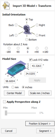
Initial Orientation
Choose one of the 6 options to determine the most suitable direction on the model that defines the top surface (upper Z) that you want to use when it's converted into a Component.
You can also use the five options for Rotation about Z Axis to modify the position of the part being imported at this stage.
To rotate the model interactively, the dynamic handles in the 3D view can be used. The red, green and blue circles allow for rotation about the X, Y and Z axes respectively, while the central grey sphere can be used for rotating around all three axes simultaneously.
Model Size
Lock XYZ ratio
Un-checking this option allows the model to be distorted from its original shape. This means independent X, Y and Z sizes can be entered. Leaving it checked ✓ fixes the ratio so it cannot be distorted. Instead it will automatically scale the other axes as you enter new values for X, Y or Z.
Apply
Applies the values you have entered for the X, Y or Z dimensions.
Many mesh files do not inherently have the units that they were made in embedde in the files, so the software is not able to tell if the files are supposed to be inches or metric, they will just have a particular value. Therefore it is quite common to need to scale the part from inch to metric or vice versa. If you import your model and you wish to work in inches and the file seems very large or if you work in Metric and the file seems very small then you will probably need to use the Scale mm/inches option. The next two items on the form cover this need.
Units
Choose the unit of measurement (mm or inches) that you are working in, within the part the file is being imported into.
Changing the units will result in resizing the model. For example, if you had 5x5 mm dimensions, they would become 5x5 inches so the model becomes a lot larger.
Scale mm/inches
Scales the X, Y and Z values up or down depending which Unit option is selected. If mm is selected then the software assumes you want to scale the values up so multiplies the current values by 25.4, if inches is selected it assumes you want to scale the values down and divided them by 25.4.
Center Model
The button which will move the center of the model's bounding box to datum position (XYZ zero). This is particularly useful if you intend to unwrap a model for rotary machining. This may change the Zero Plane position in the model.
Apply Perspective along Z
Checking ✓ this will enable you to apply a perspective distortion to the model along the Z axis by using the slider. Points on the model closest to the observer will become further apart as the distortion strength is increased - this makes the model appear as if it is coming out of the screen.
Position & Import
Selecting this button will take you to the Position & Import dialog
Cancel
Cancels the Import function and returns to the standard Modeling Tab icons.
Segment
Pressing the button leads to the segmenting form
Texture Toolpath
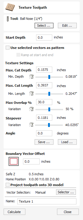
The 3D Texture Machining functionality uses a specialized toolpath algorithm and the shape of the tool to generate a textured finish on the part.
Watch this video to see this in action:
Tool
Clicking the button opens the Tool Database from which the required tool can be selected. See the section on the Tool Database for more information on this. Clicking the button opens the Edit Tool form which allows the cutting parameters for the selected tool to be modified, without changing the master information in the database. Hovering the mouse cursor over the tool name will display a tool tip indicating where in the Tool Database the tool was selected from.
Texture Settings
Use selected vectors as pattern
By default this option is unchecked and the texture form will generate a random texture pattern using any selected vectors as a clipping area. If this option is checked, ✓ the currently selected vectors will be used as the pattern for the texture and the only options available will be 'max. Cut Depth' and 'min. Depth' to control the depth of the cuts along the selected vectors.
Ramp at start and end
This option is only available when using selected vectors as patterns. If this option is checked ✓ each of the selected contours is cut using a fluting move, otherwise each of the contours is cut with a regular profile move. The resulting textures may look very different because of this small change.
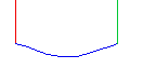
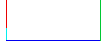
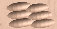
Max. Cut Depth
The maximum depth any of the carved scallops will be machined to and is specified in the job units.
Min. Depth
Using the slider this is specified as a percentage (%) of the Max. Cut Depth and controls the minimum depth any of the scallops will be machined to.
Note
For example, with a Max Cut Depth = 0.200 inches and a Min Cut Depth of 0.050 inches, the depth of the carved scallops will range randomly between 0.200 inches and 0.050 inches.
Max. Cut Length
Specifies the maximum length for any of the carved grooves and is specified in the job units.
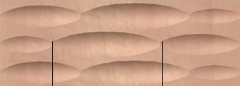
Min Length
Using the Slider this is specified as a percentage of the Max Cut Length and controls the minimum length any of the carved grooves.
Max. Overlap %
The percentage (%) of the Max Cut Length that each scallop is allowed to overlap the adjacent scallop running along the cutting direction. Where, 1% will result in almost zero overlap of adjacent scallops 50% will result in some of the scallops being machined half way over the adjacent scallop.
Variation
Using the slider this is specified as a percentage of the Max Overlap. Overlap variation of 100% = the Max Overlap and random pattern Overlap variation of 1% = No Overlap and an almost constant pattern.
Stepover
The distance between each parallel set of lines of carved scallops.
Angle
The direction the texture is machined across the surface, an angle of zero is parallel to the X axis, examples of setting the angle to 45 and 90° can be seen below.
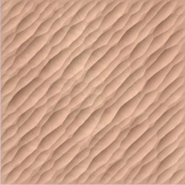
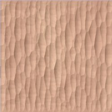
Boundary Vector Offset
If you enter a value in this field, the texturing will be offset from the boundary by the specified amount. If you are texturing in a recess, you should enter a value here up to the radius of the tool to avoid the walls of the recess being damaged by the tool.
Position and Selection Properties
Safe Z
The height above the job at which it is safe to move the cutter at rapid / max feed rate. This dimension can be changed by opening the Material Setup form.
Home Position
Position from and to that the tool will travel before and after machining. This dimension can be changed by opening the Material Setup form.
Project toolpath onto 3D Model
This option is only available if a 3D model has been defined. If this option is checked, ✓ after the toolpath has been calculated, it will be projected (or 'dropped') down in Z onto the surface of the 3D model. The depth of the original toolpath below the surface of the material will be used as the projected depth below the surface of the model.
Note:
When a toolpath is projected onto the 3D model, its depth is limited so that it does not exceed the bottom of the material.
Vector Selection
This area of the toolpath page allows you to automatically select vectors to machine using the vector's properties or position. It is also the method by which you can create Toolpath Templates to re-use your toolpath settings on similar projects in the future. For more information, see the sections Vector Selector and Advanced Toolpath Templates.
Name
The name of the toolpath can be entered or the default name can be used.
Wrapped Spiral Layout
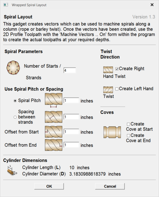
This gadget is used to simplify the task of creating toolpaths to machine spirals (rope or barley twist) on a rotary work piece. The gadget is designed to be used in a rotary job
This gadget does NOT create toolpaths directly. It lays out vectors in the 2D view which can then have toolpaths created using Profile toolpath within the main program. The top part of the form allows the user to specify how many strands to create and how far from the start and end of the work piece the strands should start and end. Strand ends are laid out evenly spaced based on the circumference of the cylinder. The spacing between strands during spiralling can be controlled using either Spiral Pitch or Spacing between strands option. It is also possible to choose between right and left hand twists.
If the user chooses to create coves at either or both ends, extra vectors will be created which can be machined with the Profile toolpath to create the coves.
For machining both spirals and coves, Machine Vectors On option should be used.
The bottom section of the form contains details about the cylinder dimensions and is presented for reference only.
After the gadget has run it will display message saying how many revolutions will each strand made and the vectors required for machining will be visible in the 2D view. Please note that the vectors will be extending beyond the 2D boundaries of the job. That is expected and thanks to wrapping feature will end up producing spirals. Please refer to Spiral toolpaths
Edit Sheet Form
The Edit Sheet form is displayed when editing one or more sheets on the Sheet Management Tab. The form is slightly different depending on the job type:
Create Component from Visible Model
The Create Component from Visible Model feature allows you to quickly create a single component which is a copy of the model shown in the 3D View (the Composite Model). The new model created is placed on the active level.
It is common when working with lots of components to find that a number of levels have been used. If, as a final step, you want to edit the models using a tool like the sculpting (which requires the components to be baked together) then they all must be on the same level, however placing the models on the same level may change the appearance of the composite model. In this case we can use the Create Component from Visible Model tool. This resulting component may then be sculpted without any of the previous modelling information being lost.
Consider the following example of a lioness we are modelling, and all of its current levels.
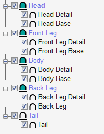

If we want to sculpt this model we must first bake it, but we currently can't bake it because the components lie on different levels. Also, baking them together will mean we lose all our structure that we have carefully built up losing the potential to edit the individual parts. So instead we use the Create Component from Visible Model tool. This creates a copy of what is visible. We can then bake this new component, and we can now sculpt without losing our structure
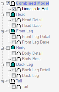
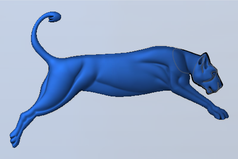
Create Zero Plane
Creates a component that is the size of your job setup with a height of Zero.
Create Texture Area
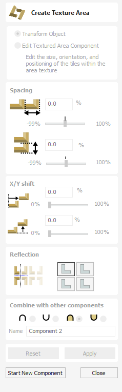
The Create Texture Area tool assists in the creation of components with a repeating pattern or texture. It requires a single component and optionally one or more closed boundary vectors which define the region in which the tiling should take place.
Watch this video to see this in action:
The Create Texture Area form is accessed from the modelling tab.
The first step is to select the component you wish to be tiled. If you want to restrict the tiling to a region then you should also select one or more closed vectors which will represent the boundary when the texture is created. If no boundary vector is selected then the tiling will fill the entire job space.
The Create Texture Area form contains options to adjust the spacing, overlap, positioning and symmetry of the texture which are discussed below. When you click the Apply button then the software will create a Component based on the settings in the form and any vector you may have selected for the boundary.
At this moment the original selected Component will be made invisible to avoid confusion with what you can see in the 3D View.
Once you click then this will effective fix the basic outline or silhouette of your Texture Area either based on the selected vector or the job area. It is possible to edit the size, position and rotation of this but if you wanted to change to a different border shape then you would need to start again with a new selection.
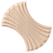
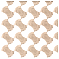
By default the form has Transform Object selected at the top. In this mode you can click on the Texture Area Component and use the drag-handles to move, scale or rotate it. Note that this will not change the size of your Tile (original seed Component). To change the size of the Tile you would use the Edit Textured Area Component option which is covered further down in this document.
Note
Create Texture Area effectively fits a box around the original object in order to apply the settings from the form, it can be useful to keep this in mind while editing the values. It's simpler to only edit one value at a time to keep track of what is happening as the Texture Area is built.
Spacing
The spacing edit box or sliders can be used to control the degree of spacing between the tiles in a pattern component. You can adjust the spacing between the components horizontally and/or vertically. The amount of horizontal spacing is given in terms of a percentage of the width of the tile component. The amount of vertical spacing is given in terms of a percentage of the height of it. To control the amount of spacing, use the two sliders in the box marked Spacing. Drag and release the slider to set the percentage, or alternatively type an exact amount into the edit box above and either hit or press the Space bar on the keyboard to update the result. You can enter both positive and negative values. Positive spacing values open gaps between the objects in the texture and negative spacing has the opposite effect making the tiles overlap one another as shown below.
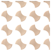
Translation : X/Y Shift
The X/Y shift option can be used to move all the tiles in alternate rows horizontally or alternate columns vertically by the specified amount. As with the spacing, the X/Y shift is given as a percentage of the size of the component in the appropriate dimension and can be adjusted using either the sliders or the edit boxes. For example entering a shift value of 50% horizontally (X) would move the second row over by half the width of the object, the third row would be as the first, then the fourth shifted, this shift would also be applied to every other row after that within the Textured Area. Similarly entering a value of 50% for the vertical shift (Y) will move every other column up by half the height of the object.
Reflection
The reflection tool consists of four buttons. Each button represents one tile in a mini-group of four, starting from the lower left copy which is represented by the original Tile. Each button has 4 states of reflection, each time the button is clicked, the icon representing the button will change to show the current state. Click to update the Texture Area Component with your new choice.


Editing an Existing Texture Area
When you have created a pattern you can edit the size of the individual Tile component you are creating a pattern from by selecting the Edit Textured Area Component option at the top of the form. Within the 2D View this will then put an orange transform box around the lower left component in the pattern. You can alter the size of this by left clicking on one of the handles and dragging it to size, when you let go this will update the pattern to fit the new size within the Texture Area boundary. You can also move the location of this Tile by clicking the center node and dragging it with the mouse to a new location. This again will change the layout of the pattern.
Note
It is not currently possible to scale or move the Tile using drag handles in the 3D View.
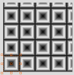
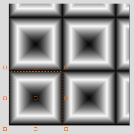
A Texture Area component will remember that it is in a special state and not a standard component. This means that they can be further edited using the Texture Area form even after Closing and re-entering the function. To edit an existing Texture Area component, select it and then open the Create Texture Area tool. Alternatively, open the Create Texture Area tool and then select the existing component. This will then let you continue to make changes to it using the form.
Resizing
Texture Area components do not behave like standard components when they are scaled in X or Y. When a Texture Area component is resized, then this resizes the boundary in which the tiling takes place so the size of the individual Tiles will not change, just the area that they are covering will be updated.
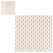
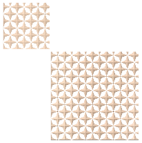
Common Modeling Options
All of the main modeling tools in the software use a common set of commands to assign a name and combine mode to the component being created along with options to apply the settings in the form, reset the shape, start creating a new component and close to exit the function.
Combine with other components...
This section includes options to allow you to name your Component and control the way it will be combined with other objects in the Component Tree.
Reset
Clicking the button will remove the current shape, doing this before you Close the form will ensure that a component is not created from the current selection. Clicking this does retain the current set of selected vectors or Components.
Apply
Clicking the button will create a shape based on the settings you have chosen. You can continue making edits to the component by choosing different parameters within the form and hitting Apply to update it.
Start New Component
Clicking the button will save the state of the component that has been created, deselect all components/vectors and start the creation process again on a new component. The values and options within the form will be retained in this case until you Close it.
Close
Clicking the button will close the form returning to the Modeling Tab icons and the updated Component Tree, reflecting any changes that you have made. If you wanted to remove the shape you just created then you can hit the Undo icon or use the keyboard shortcut to undo, CTRL+Z.
3D Finish Toolpath
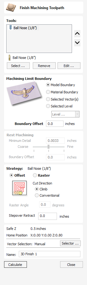
Finish Machining is used to machine the final pass on the finished 3D part.
For most 3D Finishing cuts a Ball Nosed end mill is used with a reasonably small stepover (8 - 12% of the tool diameter is typical). Variations on this tool type such as a tapered Ball Nosed cutter will also work and may offer more strength with smaller tool sizes. The size of tool will depend on the size of the part and the detail within the 3D part. Use the preview function to check the finish quality and detail; if they are not to a high enough standard then the job may require smaller tooling or a smaller stepover. 3D cutting is always a tradeoff between time and quality and an optimum balance of tool size, finish quality, and time to cut. The choices made will always depend on an individual's personal preferences or the specifications of the job.
Note
The finishing toolpath is always a single pass, and it does not use the tool's pass depth. Please ensure that your Roughing Toolpath's Machining Allowance is set appropriately for the tool used in Finishing to avoid damaging the bit.
Tool Selection
You can select any number of tools you wish to use to create this toolpath. When multiple tools are chosen then the first tool removes as much material as it can, all subsequent tools in the list will remove as much material as it can from any previously unmachined areas. If multiple tools are selected then the order of the tools in the list should match the order they will run on the machine.
Note
Sometimes an allowance will be left on for the final tool to remove.
Clicking the button opens the Tool Database from which the required clearance tool can be selected and added to the list.
Clicking the button will remove the selected tool from the list.
Clicking the button opens the Edit Tool form which allows the cutting parameters for the selected tool to be modified, without changing the master information in the database.
Clicking the up and down arrow buttons will move the selected tool up and down the list respectively.
Machining Limit Boundary
The machining limit boundary is the area in which the tool will operate. There are several options:
Model Boundary The combined boundaries of all the components in this job are used. This is the area of the composite model which has components on it. Note: this is not the boundary of the selected models.
Material Boundary The boundary of the entire material block is used.
Selected Vector(s) Selected vectors are used as the machining boundary.
Selected Level The combined boundaries of all the components on the specified level. This is similar to Model Boundary, but only specific to the named level.
Boundary Offset
If you are machining a raised object, often the tool will not fully machine down the edge. This field is used to specify an offset to the selected machining boundary to increase its size to allow the tool to go past the actual edge if needed.
Area Machining Strategy
There are two choices of the type of fill pattern that will be used to machine the area with the toolpath; Offset and Raster.
Offset

Your choice of Climb or Conventional cutting will largely be dictated by the material that is being machined and you're tooling options. Talk to your tooling suppliers for details about what is most appropriate for your specific application.
Raster

Calculates a raster pattern (lace cut) projected onto the 3D surface and machined inside the selected vector(s), with control over Raster Angle - Between 0 and 90°. 0° will give you a pattern that is mainly parallel to the X axis and 90° is mainly parallel to the Y axis.
Stepover Retract
The Stepover Retract Value can be applied to the Offset Machine Strategy. If the value you enter is greater than 0 then the tool will lift off the surface of the composite model by this amount when stepping between each offset contour. Depending on your material and tooling, adding a small lift will eliminate perpendicular tool marks between the toolpath contours to potentially improve the finished surface.
Note:
If the Stepover Retract Value specified is not large enough to allow the machine to lift the tool over the previous cusp height then you will receive a warning. This warning is simply informing you that with a Stepover Retract value of this size then you will not eliminate perpendicular tool marks.
Rest Machining
Rest machining is a technique which uses multiple tools to try and optimize for machining time, material removal and tool lifetime. A series of tools can be chosen, with each tool removing any remaining material that the previous tool was unable to machine. If multiple tools are selected then rest machining will be used.
Minimum Detail
The minimum detail value and corresponding slider controls how small an unmachined area should be if it is going to be ignored by this particular tool in the toolpath. The result of finish maching with one tool will always leave areas of the model that are not completely machined. Often these unmachined areas are so small that it is not desirable to have a smaller tool to try and machine them. For example, it is unlikely that we would want to have the smaller tool try to remove the unmachined cusps of a previously cut toolpath.
Setting the minimum detail is likely to be a compromise between achieiving greater detail versus reducing machining time.
Boundary Offset
The boundary offset value specifies a value that every unmachined area will be offset by. A low value for the boundary offset will result in this tool machining lots of smaller areas. A high value will result in this tool machining fewer but larger areas.
Position and Selection Properties
Safe Z
The height above the job at which it is safe to move the cutter at rapid / max feed rate. This dimension can be changed by opening the Material Setup form.
Home Position
Position from and to that the tool will travel before and after machining. This dimension can be changed by opening the Material Setup form.
Vector Selection
This area of the toolpath page allows you to automatically select vectors to machine using the vector's properties or position. It is also the method by which you can create Toolpath Templates to re-use your toolpath settings on similar projects in the future. For more information, see the sections Vector Selector and Advanced Toolpath Templates.
Name
The name of the toolpath can be entered or the default name can be used.
Quick Engraving Toolpath
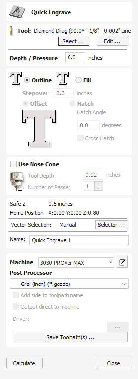
This form is used specifically for calculating engraving and marking toolpaths.
Watch this video to see this in action:
Depth / Pressure
When using Conventional Engraving and End Mill cutters the Depth to engrave / mark is specified and this z depth dimension is output in the toolpath file sent to the CNC machine. The 3D Preview of these toolpaths shows the specified depth of engraving.
When using a Diamond Drag marking Tool the Pressure setting is used to pre-load the spring to ensure the tip of the diamond stays in contact with the material surface, especially when marking uneven surfaces. The 3D Preview of the depth these toolpaths will mark using the Angle of the diamond and the Width of the Line.
For example, when using a 90° Diamond Drag Tool with a 0.010 inch Line Width specified. The depth shown in the 3D preview will be 0.005 inch (with 90° the depth = half the line width).
The ratio of Depth to Line Width will change when using diamond drag tools with different tip angles. When the option to use a Nose Cone is selected (see below) the actual depth specified on the form is used when previewing the toolpath in the 3D view.
Strategy
When using the Quick Engraving Form the Stepover for the cutter is specified on the form and is NOT automatically set from the Tool Database.
The selected text or vectors can be Outlined or Filled.
Outline
The tip of the cutter runs on the selected lines engraving / marking the material surface

Fill
A pattern is used to engrave / mark inside the selected text or vectors. There are 3 fill pattern options.


Use Nose Cone
A nose cone is often used when engraving or marking material that is not flat. The nose cone is spring loaded forcing it to slide on the surface of the material. The engraving cutter is set to extend / protrude out of the bottom of the nose cone by the depth of engraving / marking required. This is typically set at around 0.010 inches to 0.020 inches.
When the option to use a Nose Cone is selected the actual depth specified on this region of form is used when previewing the toolpath in the 3D view.
Number of Passes
This option runs the cutter multiple times divides over the toolpath pattern.
Position and Selection Properties
Safe Z
The height above the job at which it is safe to move the cutter at rapid / max feed rate. This dimension can be changed by opening the Material Setup form.
Home Position
Position from and to that the tool will travel before and after machining. This dimension can be changed by opening the Material Setup form.
Vector Selection
This area of the toolpath page allows you to automatically select vectors to machine using the vector's properties or position. It is also the method by which you can create Toolpath Templates to re-use your toolpath settings on similar projects in the future. For more information, see the sections Vector Selector and Advanced Toolpath Templates.
Name
The name of the toolpath can be entered or the default name can be used.
Immediate Output
Once calculated, your toolpath is stored in the central Toolpath Tree and can be saved, edited or output to your machine at anytime using the command. In addition though, this form also includes a convenient Immediate Output section that allows you to save or send the most recently calculated toolpath directly from this form without having to close it.
Post Processor
Use this drop-down list to select the post-processor for your machine.
Add side to toolpath name
If you are creating aligned toolpaths for a two-sided part, this option automatically adds the side name to the toolpath name as it is saved or exported to help keep your toolpaths organised.
Output direct to machine
If your post-processor supports direct access to your cnc machine (including machines supported by VTransfer), this option will be available. Selecting this option will bypass saving the toolpath to disk and instead send it straight to the direct output driver.
Trim Objects
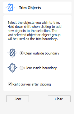
The trim tool allows you to trim all the objects inside a given boundary. It is much more efficient than manually trimming all the contours with the trimming scissors, and allows the trimming of closed contours, open contours and components.
Watch this video to see this in action:
To use:
- Select objects you wish to be trimmed
- Select the object you wish to trim against (hold shift to add to selection)
- Choose to clear inside or outside
If the Clear outside boundary option is selected then all the objects that intersect this boundary are clipped, and the area outside is removed. If the Clear inside boundary option is selected, then the parts of the selected objects which lie inside the boundary are removed.
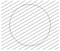
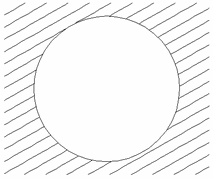
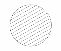
If you want to use multiple vectors for the trimming boundary, they must be grouped for trimming. To group a collection of vectors select the vectors, right click and choose Group Objects from the drop down menu, alternatively select all the vectors and press the G key.

Refit Curves After Clipping
In order to clip curves the trim tool will convert them to curves consisting of many small lines. If this option is selected then after clipping has happened the vectors will be converted to curves.
Usable In Both Views
This tool can be used in both the 2D and 3D View.
2D View offers a more direct way to view your vectors while 3D Offers more flexability to work with Vectors in 3D Designs and to make use of the Edit Boxes.
PDF Export
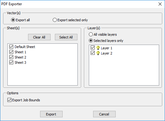
The PDF Export form allows vectors within your drawings to be exported into PDF format.
Vector(s)
Export All
Selecting this option will export all of the vectors contained on the specified sheets and layers.
Export Selected Only
Selecting this option will export only the vectors which are currently selected and on the specified sheets and layers.
Sheets
The sheets you wish to be exported to PDF can be selected from within this section. Clicking will deselect all of the sheets and clicking will cause all of the sheets to become selected. You can also manually select/deselect individual sheets by clicking on the check box to the left of the sheet name.
Note
Each sheet will be saved as a separate page within the PDF file.
Layers
The layers you wish to be exported to PDF can be selected from within this section. All the visible layers with content on them will show up in this list.
When All visible layers is chosen all of the vector layers will be selected. Only vectors on the layers selected will be exported into the PDF file. When Selected layers only is chosen individual layers can be manually selected/deselected by clicking on the check box to the left of the layer name.
Options
Export Job Bounds - If this option is selected a vector representing the boundary of the job will also be output to the PDF file.
Clicking will prompt you to choose a filename and location for your file and save your drawing in PDF format at that location.
Rotate
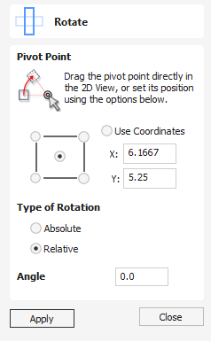
For precise control of the rotation, or to use a point other than the selection's center as the rotation center, you can open the rotation form from the Drawing Tab.
Selected items in the 2D View can be rotated to a new orientation using this tool. The rotation options form can be activated from the tool icon on the Drawing Tab. Alternatively you can use the interactive transform mode (where the form is not required) directly from the 2D View.
With this form open the additional Pivot Point handle is available (two concentric circles initially positioned at the center of your selection) for you to click and drag in the 2D View. The Pivot Point (around which the selection will be rotated) responds to the currently enabled snapping options to help you to position it precisely on significant locations within your artwork. Hold down the Shift key to temporarily disable snapping while you drag the Pivot Point.
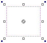
Watch this video to see this in action:
Pivot Point
On the form there are also six radio button options for snapping the rotation Pivot Point to the selection itself or to a precise position. The first five options allow you to snap to the corners and center of your selection.
Use Coordinates
The X and Y edit boxes allows you to precisely specify the position of the Pivot Point. This is also the option that will be selected by default if you drag the pivot point using your mouse directly in the 2D View.
Type of Rotation and Angle
This controls what the angle value does.
- Relative will simply rotate the object by the given angle. For example, you can enter a small angle, and then rotate multiple times to nudge the object a little bit at a time. A positive angle results in a counter clockwise rotation. A negative angle results in a clockwise rotation.
- Absolute will set the rotation of the object to the given angle. For example, setting a zero angle here will reset the rotation of the object back to its original orientation (as long as the rotation hasn't been baked).
Keep in mind that when rotating an object, it's rotation is maintained so that you can restore the rotation or scale along its original axes later on if required.
Interactive Rotation
Generally the most convenient way to rotate an object in the 2D View is to use interactive transform. This mode is initiated by clicking the selected object twice with the cursor. The process is:
- Select the object by clicking on it in the 2D View (or multiply select objects using box selection or by shift-clicking on them).
- Click the selection a second time to activate the interactive options rotation handles on the selection box.
- Click and drag on the blue handles (solid squares) at the far corners of the selection to rotate it.
Note
Holding down an Alt key when dragging to rotate the object snaps to angular rotation steps of 15° increments.
Usable In Both Views
This tool can be used in both the 2D and 3D View.
2D View offers a more direct way to view your vectors while 3D Offers more flexability to work with Vectors in 3D Designs and to make use of the Edit Boxes.
Open a File
This option opens the File Open dialog window, allowing Aspire files (CRV) and importable 2D vector files to be selected and opened.
Laser Cut And Fill
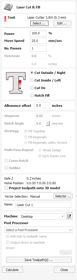
Note
The Laser Module is available as a paid-for add-on to the software. The features are not included in your software by default. To find out more about the Laser Module, please go to https://vectric.com/laser-module
Laser Cut - Fill is used for cutting out shapes or marking areas.
Cut-outs can take into account the kerf, or width, of the laser beam to maintain the precise internal or external size the selected vector shapes. Shapes can also be filled with stripes or hatching to create simple shading effects.
Tool Selection
Select Tool
This button opens your database of previously stored laser settings for different jobs and materials. When a setting is selected fromt the database it will be used to populate the key fields in this section. You can subsequenlty modify these values when calculating the laser toolpath. Modifying the settings on this form will not alter the original stored settings within your database.
Power
This value sets the proportion of the maximum laser power from your machines that will be used for this tool path.
Move Speed
This specifies the maximum speed that your machine will move during cutting or engraving moves. The units are determined by the database setting that was originally selected.
No. Passes
The machine can repeat a tool path several times to cut through thicker material. This value sets the maximum depth the machine will attempt to cut with each pass to achieve the final Cut Depth.
Overscan
Overscan allows the user to have the laser pass beyond the edge of the lasered area, to account for deceleration of the machine which would otherwise result in a darker edge to the laser burn. Overscan is machine dependant and the user will need to run some test images to identify how much overscan to use on their machine at a given feedrate to eliminate overburn at the edges of the lasered area.
Strategy
Based on the selected vector shapes in your drawing, this toolpath offers four distinct strategies.
Cut Outside / Right
Selecting this option will run the laser around the outside of your selected vector shapes (or along their right-hand edge, if they are open vectors). The actual path of the laser is automatically offset from the orginal shape according to the kerf width of the laser. As a result, the external dimensions of the resulting physical part precisely match the size of the original vector drawing. This strategy should be used for cutting out shapes to precisely the correct dimensions.
Cut Inside / Left
This option will run the laser around the inside (or left-hand edge) of your selected vector shapes, allowing for the kerf of the laser. This strategy is typically used for cutting holes, slots or sockets where the remaining recess has precisely the same dimensions as the original selected vector drawing.
Cut On
This option will run the center of the laser beam along the selected vector. No offsetting or kerf compensation is required.
Hatch Fill
This is a marking or 'shading' strategy which profiles along the selected vectors and then fills-in the shapes with stripes. When this option is selected the additional Stepover, Hatch Angle and Cross Hatch options will also become enabled - see below for more information on these.
Allowance
This setting allows you to add an additional offset for the Cut Outside, Cut Inside strategies without adjusting the laser kerf settings and can be useful for easing or tightening the fit of shapes resulting from these cuts.
Note
This option is not applicable to the Cut On or Hatch Fill strategies and will be disabled if they are selected.
Stepover
When creating hatch fills, this option determines the spacing between the hatch lines. It is only available when the Hatch Fill strategy is selected.
Hatch Angle
When the Hatch Fill strategy is selected, this option determines the angle of the hatching lines used.
Fill Together / Fill Regionally
These options will change how areas separated by spaces are treated. In the example of the word "Test" with Fill Together selected the letters will be treated as one whole space to be filled whereas with Fill Regionally each letter will be treated separately as its own individual region.
Cross Hatch
Checking this option will create a cross hatch fill instead of a single set of lines.
Outline
Selecting this option will then create a defined outline around a chose vector. If unchecked there may be gaps around the edges if the stepover is large enough whereas when checked an outline passing around the outside will appear.
Position and Selection Properties
Safe Z
The height above the job at which it is safe to move the cutter at rapid / max feed rate. This dimension can be changed by opening the Material Setup form.
Home Position
Position from and to that the tool will travel before and after machining. This dimension can be changed by opening the Material Setup form.
Project toolpath onto 3D Model
This option is only available if a 3D model has been defined. If this option is checked, ✓ after the toolpath has been calculated, it will be projected (or 'dropped') down in Z onto the surface of the 3D model. The depth of the original toolpath below the surface of the material will be used as the projected depth below the surface of the model.
Note:
When a toolpath is projected onto the 3D model, its depth is limited so that it does not exceed the bottom of the material.
Vector Selection
This area of the toolpath page allows you to automatically select vectors to machine using the vector's properties or position. It is also the method by which you can create Toolpath Templates to re-use your toolpath settings on similar projects in the future. For more information, see the sections Vector Selector and Advanced Toolpath Templates.
Name
The name of the toolpath can be entered or the default name can be used.
Immediate Output
Once calculated, your toolpath is stored in the central Toolpath Tree and can be saved, edited or output to your machine at anytime using the command. In addition though, this form also includes a convenient Immediate Output section that allows you to save or send the most recently calculated toolpath directly from this form without having to close it.
Post Processor
Use this drop-down list to select the post-processor for your machine.
Add side to toolpath name
If you are creating aligned toolpaths for a two-sided part, this option automatically adds the side name to the toolpath name as it is saved or exported to help keep your toolpaths organised.
Output direct to machine
If your post-processor supports direct access to your cnc machine (including machines supported by VTransfer), this option will be available. Selecting this option will bypass saving the toolpath to disk and instead send it straight to the direct output driver.
Draw Circle
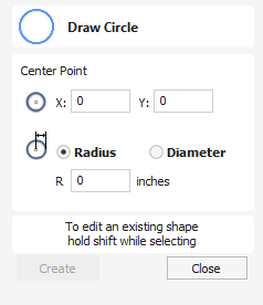
Circles can be created interactively with the cursor and Quick Keys or by entering the exact coordinates and diameter / radius with typed input.
Watch this video to see this in action:
Interactive
Cursor
The default mode and the procedure for drawing circle is:
Click and drag the Left mouse to indicate the center point followed by releasing the button at the required radius / diameter (depends on what is set on the form).
Note
Holding Alt and dragging creates a circle from the middlepoint.
As the cursor is dragged across the screen the radius is dynamically updated. The increments will depend upon your snap radius and the job size.
Quick Keys
The radius or diameter can be specified while dragging out a circle:
Type the value while dragging followed, by D if it's a diameter, or R if it's a radius:
Example:
1 2 R Gives a radius of 12
Exact Size
Circles can also be drawn by entering the required XY origin, selecting either Radius or Diameter and entering the required size on the form.
Click Create to update the circle.
Edit
Open the Draw Circle form and select the circle to modify.
The selected circle is displayed as a dotted magenta line. Edit the Center Point and Radius or Diameter
Click to update the circle
To modify another circle without closing the form hold a Shift key down and select the next circle.
Close the form
To finish drawing with the tool, you can :
Click Close on the form
- Press the key Esc
- Click the Right mouse button in the 2D View
Usable In Both Views
This tool can be used in both the 2D and 3D View.
2D View offers a more direct way to view your vectors while 3D Offers more flexability to work with Vectors in 3D Designs and to make use of the Edit Boxes.
Freehand Drawing
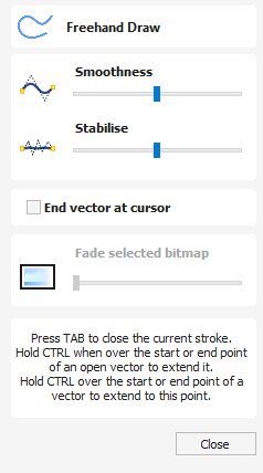
This tool will allow the user to draw both open and closed vector paths in a freehand style which closely mimics the flow of drawing with a physical pencil and really excels at creating quick initial design sketches and organic flourishes.
Optionally paired with a Windows compatible graphics tablet, this tool will enable you to draw your paths with a stylus, giving a more faithful simulated drawing experience.
The resulting image you see on screen still exists as vector information including automatically placed nodes and handles, meaning that you then have the option to use the same shape editing tools as any other path within the software to further edit and manipulate the vectors you have initially created with the Freehand Draw Tool.
Watch this video to see this in action:
Open paths with Freehand Drawing Tool
1. Under the create Vectors section of the Drawing panel > Select the Freehand Drawing Icon.
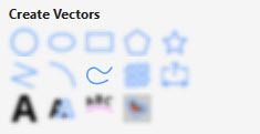
2. Left click and hold within the workspace to place a first point and the path will then follow the direction of your cursor. Whilst active the cursor will change to a Cross-hair and the drawn path will follow it's centre point.
Note
If Stabilisation is applied, a reticle will appear next to the cursor. This is explained under Freehand Draw Options below.
3. Release to place end point and finalise path.
Close Current Stroke
Whilst actively drawing an open path click TAB To join the the current point with the Path's start point creating a closed vector shape
Extend Existing open Vector path
In order to extend an existing open vector using the Freehand Drawing tool;
1. Hover your cursor over the point you wish to join from
2. Holding down Ctrl > within the immediate area of this point > Drag to draw path
3. Release to complete path.
Join On to Existing Vector
Whilst you are actively drawing a path with the held down, and you would like to join this to an existing open vector;
1. Press and hold Ctrl > Hover cursor over the Start or end point of another open vector
2. Release To complete path and join this to existing open vector line, creating one continuous path.
Freehand Draw Options
Smoothness
This option, controlled by the below slider, controls to what extent smoothing is applied when the is released and the path completed.
The further the slider is to the left the smaller the amount smoothing that is applied and any angular changes in direction will be retained once the is released and the path completed.
The further the slider is to the right the greater the level of the smoothing effect that is applied; Sharp angles are smoothed into curves and the path is simplified with fewer individual nodes created.
Stabilise
The stabilisation setting controls how much small movements with the mouse or stylus will be damped out whilst drawing.
This is controlled within the form by the below slider;
The further the slider is to the left, the less stabilisation is applied when drawing and even small changes in direction from the mouse/stylus will show in the resulting path.
The further the slider is to the right, the more stabilisation is applied and the tool will damp out small jitters in the mouse/stylus movement to produce a smoother path.
When an amount of stabilisation is applied a circle will be shown around the start point of the path when you start drawing and follow the end point of the path. Within the zone of this circle movement of the cursor will not extend the path. The cursor needs to move to the edge of this zone at which point the path will start moving towards the cursor. As cursor movements within this zone do not affect the path it also allows precise sharp changes of direction as you can move the cursor back into this deadzone then off in a different direction easily.
End Vector at Cursor
With this option unchecked; when the left mouse button is released, the end point of the actively drawn path will be placed in the centre of the reticle which appears to indicate the level of stabilisation being applied.
If instead you wish for the end point to be placed in the position of the cross hair cursor when the button is released, you can check the box next to this option. As the end point will remain the same regardless of the level of stabilisation applied, this can lead to greater accuracy in predicting the end of your drawn path.
Fade selected Bitmap
One of the many useful applications for the Freehand draw tool is for greater control over the tracing of imported bitmap images. By using the Fade selected Bitmap slider, the user can control the level of transparency for the selected Bitmap you are tracing over.
The further the slider is to the left - The lower the transparency of the selected bitmap, until completely opaque.
The further the slider is to the right - The level of transparency increases, giving the drawn path higher contrast against the traced image and making it easier for the user to distinguish on the screen.
Exiting Freehand Draw Form
Once you have completed your drawing and wish to exit from the freehand draw form, either;
- Click the
- Or Press the 'Close' button at the bottom of the form in the drawing panel.
Usable In Both Views
This tool can be used in both the 2D and 3D View.
2D View offers a more direct way to view your vectors while 3D Offers more flexability to work with Vectors in 3D Designs and to make use of the Edit Boxes.
Create Fillets
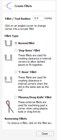
Fillets or radiuses can be added interactively at points where any two spans on a contour meet.
Watch this video to see this in action:
Creating Fillets
To use the filleting tool we select the icon from the drawing tab. Choose a radius for the fillet and the type of fillet you would like to use.
When the mouse cursor is near a node that can be filletted, the mouse cursor changes to show a check-mark ✓:

Fillet Type
Normal Fillet
This creates a standard corner fillet based on the Radius defined, typically this would be used for design purposes and not for editing a slot for fitting purposes. Below left the image shows the vector before filleting the two inside radii, on the right is the filleted version
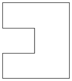
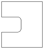
Dog-Bone Fillet
This creates a circular cut-out style of fillet, the circles will be placed so the upper right part of the circle touches the original sharp corner and are created with the Radius specified. This option should not be used if the slot width and the tool are similar in size. Below left is the vector showing the slot before filleting, on the right is the filleted version using the 'Dog-Bone' option.
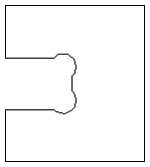
T-Bone Fillet
This creates a circular cut-out style of fillet, the circles will be created with the Radius specified. This option should be used if the slot width and the tool are similar in size so the slot can grow out to the side to ensure there is space for them to fit. Below left is the vector showing the slot before filleting, on the right is the filleted version using the 'T-Bone' option.
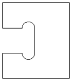
The placement of the fillet is an interactive process; you can choose which side of the 'corner' the T-bone filet is placed. If you click on a 'corner' the fillet will be placed automatically on the longest side. By clicking to the side of the corner you want the fillet placed you can choose which side the fillet is placed on.
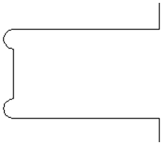
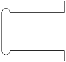
Removing Fillets
Fillets can be removed in the same way that we add fillets: move the cursor over the fillet that you wish to remove.
If this fillet can be removed then the cursor shows a cross to indicate that it is possible to remove a fillet:

Clicking removes the fillet:
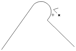
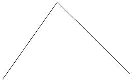
When removing fillets the software does not store what kind of geometry the fillet was created from. It always defaults to using straight lines to return the fillet to a sharp corner. As such if the fillet is across multiple spans or is derived from arcs or Bezier curves then it will not go back to its original state and instead it will remove the radius and extend two straight lines to create the new corner.
Extend Vectors
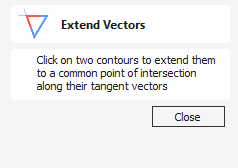
This tool allows you to extend two vector lines to their common point of intersection.
With the Extend Vectors tool active, moving the mouse pointer over the ends of open vector shapes (without clicking) will highlight a dashed preview extension line from that shape. The line will change dynamically as you move the mouse over the end spans of different open shapes. Clicking with the left mouse button at this point will set it as the target line to extend and the magenta line will remain visible.
The mouse can now be moved over existing spans along the length of the preview extension line, or over the end of another shape to create a second, intersecting, preview extension line.
Clicking on any of the intersection points indicated by the mouse cursor will extend the initial shape to that point and complete the operation.
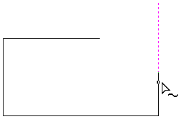
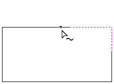
The tool can be closed at any time using the button on the form. Right-clicking in the 2D View will reset the tool so that it is ready to select another target line to extend.
Watch this video to see this in action:
Drag Knife Toolpath
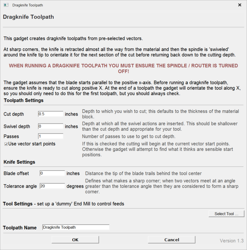
This Gadget supports drag knife tooling in your CNC machine. It uses the selected vectors in the 2D View as the basis of a centerline profile-type toolpath that incorporates swivel moves at corners to ensure the drag knife blade remains properly aligned throughout the cut.
Warning
When machining please ensure you have the spindle switched off.
Blade Offset
The tip of a drag knife is offset by a small amount from the pivot center of the tool to allow it to swivel as it cuts. This value specifies the distance and will be provided by your tool manufacturer.
Tolerance angle
This value determines when a swivel move needs to be used on a corner. Changes in tool direction, or corners, with angles less than this value will not generate swivel moves.
Cut Depth
This value sets the final cut depth of the toolpath. It defaults to be the current material thickness.
Swivel Depth
The knife must remain in some contact with the material in order to swivel correctly, but a small retraction is generally used to lift the knife blade slightly to minimize marking the material during the swivel action. This value must, therefore, be less than the cut depth and appropriate for your tool and material.
Passes
This value determines the number of passes used to cut down to full depth. The depth of each cut will be specified cut depth divided by the number of passes.
Use Vector Start Points
If Use Vector Start Points is checked ✓ then the gadget will use the existing vector start points to begin cutting vectors. Please note that this gadget assumes that the blade starts parallel to the positive x-axis. If this is option not checked the gadget will attempt to find what it thinks are sensible start positions.
Feed and Plunge Rates
These are the rates that the machine will push the knife through the material during a cutting pass, and the rate of descent of the tool into the material at the beginning of a cutting pass. Please ensure that the values are appropriate for your machine tool and the material you are cutting.
Job Setup Sheet Editor
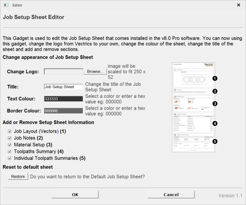
The Job Setup Sheet Editor is a gadget which enables you to personalise the existing Job Setup Sheet that you can generate from the Toolpaths Menu. You can access the gadget from the Gadgets Menu.
Change Logo
To change the logo from the default Vectric logo, press the button. This will open a dialog box enabling you to search your local computer for images to select. Images in landscape are better suited as they will be scaled down to W165 x H52 pixels. Images must either be JPG, PNG or GIF file format.
Title
To change the default title of “Job Setup Sheet”, enter the desired title in the edit box.
Color options
There are two options to change the color of the Header and Footer blocks, you can either: Point and click the mouse in the colored edit box, this will bring up the color selector, select a color and then click anywhere outside of the selector to accept this. Type a colors hex value directly into the edit box.
Add or Remove Setup Sheet Information
Each of the 5 sections of the Job Sheet can either be included or removed to display as much information as required. The image to the left, represents a default Job Sheet which includes the following 5 sections:
- Job Layout
- Job Notes
- Material Setup
- Toolpaths Summary
- Individual Toolpath Summaries
Restore to default sheet
Upon first successful run of this gadget, it will detect if you have already created a modified version of the Job Setup Sheet within the public gadgets directory, if so it will backup this Gadget so you could, if required restore it at a later date. If no modified gadget is found, it will backup the software default "Job Setup Sheet" so you have a copy if you want to revert back to the standard layout at a later date.
14. Advanced - Imported 3D Toolpath Files
Files from Vectric's Cut3D, PhotoVCarve and Design and Make Machinist that include 3D toolpaths can be imported into Aspire using the main menu command: File ► Import ► PhotoVCarve, Machinist or Cut3D Toolpaths.
The 3D file must first be scaled to the required size before toolpaths are calculated, and then the complete file saved ready for importing into Aspire. These files can only be moved and positioned inside Aspire but cannot be scaled.
A Grayscale thumbnail of the 3D job is drawn in the 2D View with the X0 Y0 origin at the position it was set in Cut3D, PhotoVCarve or Design and Make Machinist. The associated toolpath(s) are also drawn in the 3D window and the names appear in the Toolpath list.
Positioning
To move the 3D design toolpaths open the 2D Window, click the Left mouse Twice on grayscale image (turns light Blue to indicate it's selected), then drag to the required position, or use the Move or Alignment tools for accurate positioning.
The toolpath(s) are automatically moved in the 3D window to the same XY position as the image.
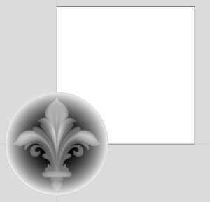
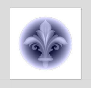
Toolpaths for the example above have been calculated with the X0 Y0 in the middle of the 3D design. When imported into Aspire the data is automatically positioned using the same coordinates, which places three quarters of the design off the job. In the second image the grayscale image has been moved to the middle of the job.
The 2D mirror and rotate drawing tools can also be used to edit the 3D data set.
3D toolpaths can also be copied using the Duplicate Toolpath command on the Toolpaths Tab making it very easy to use multiple elements from a single design on a job. The thumbnail preview is also copied for each toolpath, making it very easy to position additional copies of a 3D toolpath.
For example, a single design can be copied and mirrored to create Left and Right versions of a 3D design or to place multiple copies of a decorative design in the corners of a cabinet door panel as shown below.
Toolpaths for the 3D elements can be previewed along with the conventional Profile, Pocketing and Drilling toolpaths, and everything will be saved ready for machining.
A good example of where this functionality might be used in conjunction with PhotoVCarve is for making personalized picture frames that include the PhotoVCarve grooves plus descriptive engraved text and a decorative Profiled or Beveled border. As shown below:

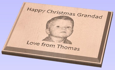
Options
Imported toolpaths can also be edited to position them inside the material or to change the cutting parameters - speeds and feed rates can be changed.
Design and Make Machinist
When using a Design and Make Machinist file that includes multiple toolpaths, you must remember to edit the Start Depth for all of the imported 3D toolpaths.
Click the Edit toolpath icon or Double click on the toolpath name to open the edit form.
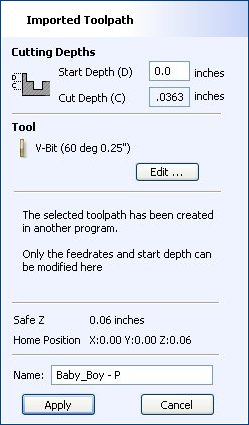
For example, after machining a half-inch deep pocket a PhotoVCarve design can then be edited to have a Start Depth = 0.5 inches and this will carve the photograph onto the base of the pocket surface.
Machine
Machine Configuration... | Opens Machine Configuration dialog. |
Add Machine... | Adds a new machine and opens Machine Configuration dialog. |
Install Offline Package... | Opens a File Dialog for selecting a package with Machine Configuration(s) |
Search for Machine Online... | Brings up Search for Machine Online dialog. |
Post-Processor Management... | Gives a list of all installed Post Processors and allow the user to Check the Changelog, Customise a duplicate of a Post Processor or simply View the Post Processors current formatting. |
Install Post-Processor... | Opens a File Open dialog box where you can install a post processor. |
Update Post-Processor Database | Downloads a latest version of the Post-Processor Database. |
Plate Production
This command is for designing and engraving multiple badges or nameplates using variables for positioning imported data from a text file list. The production plate functionality is typically used by engravers making badges from a database file supplied by a customer, but could also be useful for making nameplates for hotel rooms with consecutive numbering.
Watch this video to see this in action:
Procedure
Draw and Setup the Master Template
Create a New job and specify the Material Size to equal the Sheet size the badges will be cut from.
Layout the badge / plate at the required size and using the Text Tools add variables where imported data / text is required. Variables are defined using double exclamation marks ('!!') at the start and end of the variable name.

Calculate Toolpaths
Select and calculate the toolpaths for each of the elements on the design. For example, calculate an engraving toolpath for the text and logos and a separate Profile cut-out toolpath around the outer edge to cut out the design
Use the Plate Production Tool on the master template
With all of the vectors that make up the master template selected, click on the Plate production tool to open the Plate Production Dialog window.
The Plate Production Dialog
The left side of the Plate Production form is used to layout the plates / badges on the selected sheet of material, and shows the total number of plates that can be engraved / machined from each sheet of material.
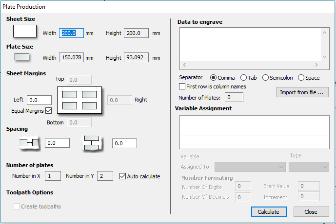
Material Size
This is the material sheet size that the badges will be engraved onto. If the number and size of the badges requires additional sheets of material to be used the software automatically creates a separate layer for each sheet required.
Plate Size
This is the size of the selected Plate / Badge and is based on the bounding box of the selected vectors.
Sheet Margins
This specifies the border margin between the edge of the material sheet and the plates.
Independent margin spacing can be set for the Top, Bottom, Left and Right sides of the material
Equal Margins ensures the same space is added around all 4 sides of the plates.
Spacing
This is the horizontal and vertical spacing between each Plate / Badge.
Number of Plates
The number of plates that will fit on to the specified material sheet size is automatically calculated. This calculation takes the plate size and adds the Sheet Margins and Plate Spacing to determine the maximum number of plates that can be made from each sheet.
Toolpath Options
If toolpaths have been calculated for the master Template this option is available.
Checking ✓ this option automatically calculates toolpaths for all the plates / badges in the project.
Unchecking this option only creates the vectors for each plate / badge.
Import the Data to be Merged into the Template
The right-hand side of the Plate Production form is used to select the data that will be merged into the template, and how the data will be interpreted to create each plate / badge
Import the required text / data file using and select the appropriate format separator.
The data file is commonly created using a spread sheet such as Windows Excel. Use the option to Save As or Export to obtain the required file format that includes the correct Separator information.
Separator
The separator is the method used in the data file for dividing each set of information into columns. The most commonly used options are: Comma, Tab, Semicolon or a Space
First row is column names
It's very common for the first row of data in a file to simply show what each of the field names are, and this information is not used on the badge or plate. Checking the box First row is column names tells the software to start working with data from row 2
Assign the Variables to the data in the text file
All of the variables specified on the template - text with double exclamation marks '!!' on either side '!!' are automatically listed on the form. These variable names are each assigned to a data field (column of text) inside the data file.
Variable Assignment
Click to select a Variable Name then select the data field from the imported file that is required on each badge / plate i.e. the person's name
Repeat for each of the Variable Names listed on the form
Number Formatting
Variables can be assigned to Text from a data file - Names, Dept., etc. or to a Counter number that can be formatted and incremented using the Number Format options.
Calculate
Click to create all Badges and associated Toolpaths
If toolpaths have previously been calculated for the vectors in the Master Template, the option to automatically Create Toolpaths for each badge / plate is switched on in the bottom left corner of the form.
Close
Click to finish plate production and close the form
Multiple Sheets
Multiple Layers are automatically created if multiple sheets of material are required to engrave all of the badge data from the imported text file. Layer named Sheet 1 is displayed in the 2D view showing the badges on this sheet.
Each of the Sheets is on a different layer and can be set visible or invisible using the Layer Manager.
Multiple Toolpaths
When Toolpaths are automatically calculated, a separate toolpath for each operation on each sheet of material is calculated and named using the convention 'S1 - Name', where the Name is the name of the toolpath previously calculated for the template.
Machine Configuration Management
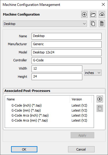
This dialog is used to edit and manage the list of machines for use in the tool database. It is also used for associating post-processors with those machines for use in Toolpath Saving. It can be accessed through the Machines Menu, the Tool Database dialog, or the Toolpath Saving form.
Watch this video to see this in action:
Machine List
List the machines added to the database. Selecting a machine activates it. This allows it to be edited in this dialog. In the Tool Database dialog, it results in switching the cutting data of the tools to be the set defined for the active material / machine (if any).
Add Machine
Add a new machine to the database and makes it active ready for editing.
Install Offline Package
Allows you to install a machine package which was downloaded from your V&Co account. If you are online, it may be better and more convenient to use the Search Machine Online tool directly from within the software.
Machine packages are preconfigured machine configurations which come pre-associated with compatible post-processors and ready with an initial set of Feeds & Speeds for a set of tools. This can all be done manually through this dialog as well, or edited subsequently following the install.
Search Machine Online
This takes you to the Search Machine Online dialog to download a machine package from our online services.
Duplicate Machine
Duplicates the active machine and makes the new machine active ready for editing.
Copy Cutting Data
This could optionally duplicate all the cutting data associated with the original machine for all the tools so that there is a new set of cutting data for the new machine as well.
Delete Machine
Delete the active machine and activate the next one up in the list.
Deleting Cutting Data
This is a destructive process deleting all the cutting data associated with this machine across all the tools.
Name
Allows us to set the active machine's name (if any). Two machines cannot have the same name.
The remaining parameters are optional and can be left empty. They define various common properties of the machine which may help you to identify them and us to tailor the behaviour in future versions.
Associated Post-Processors
This allows you to manage the list of post-processors associated with this machine configuration.
Through this, you can Add or Remove a post-processor. Right-clicking on the post-processor gives you some of the options available in the Post-Processor Management dialog, or set it to a fixed version.
Adding & Removing a Post-Processor
This will allow you associate a post-processor to this machine configuration by selecting it from the list of available post-processors.
You can also remove this association using the 'Remove' button. This will not remove the post-processor from your machine, but will simply disassociate it from the current machine configuration.
Post-Processor Version
Clicking the version displayed in the second Version column will popup a list showing the available versions of this post-processor.
- Latest (Vn) where n is the latest version: Allows to keep using the latest version of the post-processor along with subsequent updates we may ship to it.
- Vn where n is a version: Allows you fix the version of the post-processor you're using to version n. Subsequent updates to this post-processor will not be used unless you specifically update to it.
Removing a Post-Processor Version
There may be occassions where a version is removed for your version of the software (or for a future version) for fixing of major issues or because of an incompatibility with that version of the software.
Right-Click Options
You will get many of the options available to you in the Post-Processor Management dialog.
A couple of notes,
- will display your currently selected version of the post-processor
- will set a post-processor to be selected as the default post-processor when using in Toolpath Saving.
Apply Changes
Apply changes by clicking or . Clicking will discard any changes made.
Dimensions
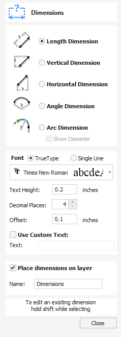
This tool allows you to add a variety of dimensioning annotations to your vector drawing.
Watch this video to see this in action:
Creating Dimensions
Unless otherwise noted below, dimensions are created by following these steps:
- Select the dimension type you wish to need: length; height; width; angle or the radius or diameter of an arc.
- In the 2D View, click with the left mouse button to set the points the dimension needs:
For an Angle Dimension, the first point is the centre-point. - Click where you need the arrow-tips to be.
- Click to set the location of the dimension-line.
- Click to set where the annotation text will appear.
Editing Existing Dimensions
To edit an existing dimension while the form is open, hold down aShiftkey while selecting it.
Dimension Types
The dimension tool supports a number of different dimension types.
Length Dimension
Use this to dimension a straight-line length in any orientation between two points.
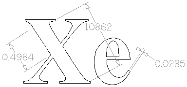
The text preview box will snap to to the middle of the dimension line, unless a Shift key is held down while dragging.
Vertical / Horizontal Dimension
These two options also allow you to select any two points, but the resulting dimension will be locked to indicate a vertical or horizontal distance (respectively) between the two points.
The text preview box will snap to the middle of the dimension line, unless a Shift key is held down while dragging.
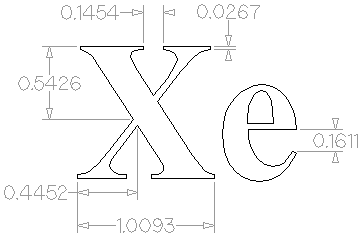
Angle Dimension
This option allows any arbitrary angle to be measured. The process is similar to creating a 3 point arc. First you must pick the center of an angle you wish to measure - typically a corner point. The next 2 points clicked will set the extents of the sweep you are measuring. The next Click will determine the dashed dimension line positioning and the final click will set the position of the text annotation.
- Angle Dimensions' arrow-heads will pop outside small angles if there is not room to draw them inside.
- Angles are extended with a dashed extension-line where required, allowing the dimension to be placed anywhere. The text snaps to the angle center and the leader-line angle snaps to horizontal, vertical or diagonal (disable snapping by holding down aShift key).
- Angle Dimensions use a separate Decimal Places value to the other dimensions (as you change dimension-type you may notice the Decimal Places value change).
- Angle dimensions can now have up to six decimal places.
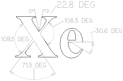
Arc Dimension
With this option selected you will only be able to select arc spans with the first click of dimension tool (Bezier curve spans are not supported). The second click will set the position of the dimension annotation, which will show the radius (or diameter) of the selected arc span.
- To display the diameter of an arc dimension simply check ✓ the Show Diameter box.
- Arc Dimensions recognise when a circle has been selected and allow placement anywhere around the circle. Arcs will now be extended with a dashed extension-line where required, allowing the dimension to be placed anywhere. The text snaps to the arc/circle center and the leader-line angle snaps to horizontal, vertical or diagonal (disable snapping by holding down a Shift key).
Note
Circles or arcs that are polygonized (from an imported file or from the Curve fit vectors command using Straight lines) are not recognized and cannot be dimensioned with this tool
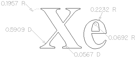
Font Selection and Settings
This section of the form allows the user to change the settings for the dimension annotation, such as the font to be used, the height of the text and how many decimal places are required. The Offset field determines the gap left between the dimension markers and the vectors that are being measured.
Use Custom Text
You can check ✓ Use Custom Text to insert your own custom text. The text is stored per dimension, so you change between calculated and custom text without losing a dimension's custom text. When the form is first opened it defaults to calculated text.
Place Dimensions on Layer
By default this option is checked ✓ and the dimensions will be placed on a mid-gray Dimensions Layer. You can edit the name of the layer in the Name edit field. If a layer of this name does not exist, it will be created automatically.
Note
Dimensions can be edited. Hold shift while selecting the dimension you wish to edit or use the Undo shortcut Ctrl+Z to undo previously created Dimensions while still in the Dimensioning tool.
Join/Close by Moving End Points
Join Moving End Points finds the closest end points on 2 selected, open vectors, calculates the mid-point between them and moves the end points to this position.
Watch this video to see this in action:
Usable In Both Views
This tool can be used in both the 2D and 3D View.
2D View offers a more direct way to view your vectors while 3D Offers more flexability to work with Vectors in 3D Designs and to make use of the Edit Boxes.
Tool Database - Name Format
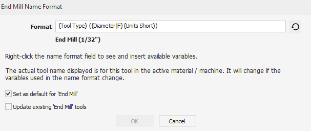
This dialog allows the editing of the name template used for naming tools with that tool type. It can be accessed through the name icon on any of the tools on the Tool Database dialog, and it will affect that particular tool or all tools with the same type.
Format
This field allows entering the name format / template that will be used for this tool (or tools of this type, controlled by the checkboxes).
The template contains variables of the format {Variable Name} which will be substituted by their real value for the tool.
- For example,
{Tool Type}will be End Mill for an End Mill tool and Ball Nose for a Ball Nose tool. - We can optionally format those the values in certain ways using modifiers
{Variable Name|Modifier}. In the above example,{Tool Type|U}would result in END MILL or BALL NOSE.
The list of all available variables and modifiers is available at the bottom of the page. It can also be accessed by right-clicking the field and selecting the variable.
Variables could relate to the tool geometry, cutting data or even machine and material being used. The tool name will automatically update within the current context. For example,
- We have materials MDF and Oak and a tool with the name template
{Tool Type} {Diameter} {Material Name}. The tool is an 0.5 inch End Mill. - When the MDF material is active, the name of the tool becomes End Mill 0.5 MDF. When it Oak is active, it becomes End Mill 0.5 Oak.
- When the tool is selected for toolpathing, the name of the tool with the correct material name will be used allowing you to see straight away which variant of the tool you've used.
Set as Default
This dialog can be used to manage name formating for each tool type. When a format is set as the default, any subsequently created tools will be named according to that format by default. Setting a format as a default (optionally) allows you to do just that.
Any tool which does not have the default name format for its type can be restored using the next to the format field.
Update existing tools
When changing the name format of a tool, there is the option to rename all the other tools with with the same Tool Type.
If you select this, you will have the option to either
- Rename all the tools that had a matching name.
- Rename all the tools indiscriminantly.
List of Variables
Here is the complete list of variables that can be used in the format.
In some cases, we may not be able to find a valid value. For example, if we use the {Material Name} when no material is active. In this case, we will simply keep the name of the variable in the tool name. This should not happen if the tool is valid / suitable for toolpath selection.
Variable | Type |
|---|---|
Geometry | |
| String |
| String |
| String |
| Float |
| Float |
| Float |
| Float |
| Float |
| Integer |
| Integer |
Cutting Parameters | |
| String |
| String |
| Float |
| Float |
| Float |
| Float |
| Integer |
| Float |
| Float |
Feeds & Speeds | |
| String |
| Float |
| Float |
| Integer |
| String |
| Float |
| Float |
| Integer |
Material | |
| String |
Machine | |
| String |
| String |
| String |
| String |
List of Modifiers
Modifiers can be used on any variable. Valid modifiers depend on the type of the variable.
Variable Type | Modifiers |
|---|---|
String | U Uppercase Example: |
| L Lowercase Example:
|
Float | 00.00 Padding / Decimal Points
Example (For a 1.5101 diameter),
|
| F Fraction in inches Example (for an 1/8 inch diameter):
|
Tool Database - Remote Tool Databases
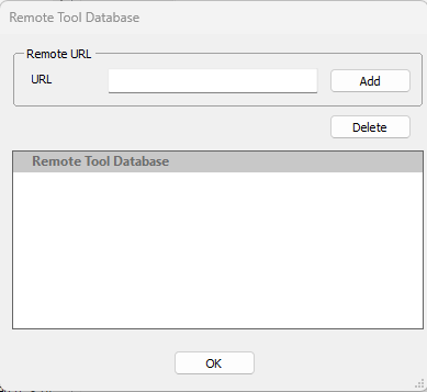
Users can share their own database via link sharing. Updates to the database (through our Cloud Upload functionality) can be downloaded by subscribers. Users can stop sharing their database at any point.
Share
To share your database, you must have first uploaded your local database through the cloud backup functionality in the tool database. Then go https://portal.vectric.com/toolDatabases and you should see your database there. You may see multiple entries for each version you have.
When you toggle the ‘share’ button, you will see a link which you can copy to the clipboard to share with others.
Update
Updating the database works in exactly the same way as the online backup. If you’ve chosen to share your database then subscribers will get the latest update that you upload so you don’t have to do anything extra here.
Subscribe
You can enter this dialog by using the ‘Remote Databases’ button to the right of the tool database selector on the Tool Database dialog.
Once you enter, you can enter the database URL supplied to you by copy-pasting into the URL field and clicking . This will download the Remote Database and will add it to the list.
As a subscriber, you will only be able to open those in read-only mode.
You can remove a Remote Database from your system be selecting the Database entry in the Remote Tool Database list and clicking .
Now in the main Tool Database Window you can select this Database from the Middle Dropdown menu to switch between them. Remote Databases are open in read-only (all settings will be greyed out and unchangeable).
- These tools can then be used in toolpaths, and edited with the Edit option in a toolpath as a normal tool.
- You can also right click tools in the Remote Database and copy them to your personal Databases for editing.
- Tools or groups can be exported into a separate tool database through the ‘Export’ button at the bottom.
This allows Shared machines to have a fixed Tool Database ready to go and be distributed easily. It allows users to share their databases and feeds & speeds with each other.
Your own database will remain unaffected and completely separate under the entry in the list called ‘Local’ unless you explicitly copy a tool to it.
Cut Operation
The Cut tool removes the selected objects from a design in a similar way to pressing the Delete key, but the selected objects are copied to the clipboard and can be Pasted into either the current file or a new file if required. Only one item can be Cut or Copied at a time.
Material Management
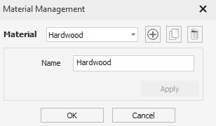
This dialog is used to edit and manage the list of materials for use in the tool database. It can be accessed through the Toolpaths Menu or the Tool Database dialog.
Material List
List the materials added to the database. Selecting a material activates it. This allows it to be edited in this dialog. In the Tool Database dialog, it results in switching the cutting data of the tools to be the set defined for the active material / machine (if any).
Add Material
Add a new material to the database and makes it active ready for editing.
Duplicate Material
Duplicates the active material and makes the new material active ready for editing.
Copy Cutting Data
This could optionally duplicate all the cutting data associated with the original material for all the tools so that there is a new set of cutting data for the new material as well.
Delete Material
Delete the active material and activate the next one up in the list.
Deleting Cutting Data
This is a destructive process deleting all the cutting data associated with this material across all the tools.
Name
Allows us to set the active material's name (if any). Two materials cannot have the same name.
Apply Changes
Apply changes by clicking or . Clicking will discard any changes made.
Create Shape - Smooth
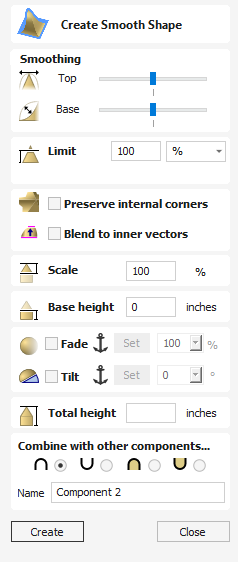
The Create Smooth Shape tool creates a 3D model component that has a smooth curve at the bottom and top of the model creating an S shape.
Watch this video to see this in action:
Smoothing
This determines how much of a curve the smoothing has on the top or bottom of the model.
You can use the slider bar to edit the angle of the curve used for the smoothing at the top and bottom of the model, having the slider bar closer to the minimum will create a more concave curve and the maximum will give a more convex curve.
Limit
This will limit the height of the shape created. This can be entered in as a value or you can use the slider bar in the drop down menu.
Preserve Internal Corners
When creating a shape using both external and internal vectors, the resulting component will have both external and internal corners. In this scenario, with this option unchecked the internal sides of the resulting shape would curve into the centre line at which the two sides meet if you draw a straight line from the top peak of the corner to the base of the shape, creating rounded internal corners.
Enabling this option by checking the box will mean that these internal sides will be comprised of a completely straight sided skeleton until both sides converge at the centre line of the corner, creating a defined sharp crease and an internal corner which will come to a sharp point as if the corners have been perfectly mitred.
Note
A good way to visualise the effect of this is to imagine looking at a corner of a building where two separate wings with pitched roofs meet, you’d expect to see a straight faced slope rather than a bowed slopein the corner from the ridge to the eaves. With this option deselected the slope would be pinched and curved inwards towards a single point in the corner.
This is best demonstrated with examples that use a polygonal base vectors;
Blend To Inner Vectors
This option applies the selected profile across the selected vectors. It blends to the profile from the outside of the vectors to the inner vectors
Scale
This limits the height of the shape by scaling the shape up or down while retaining its general specified profile. It is scaled to the height entered in the Height area of the form which becomes available once this option is selected. The slider can also be used to change the final height.
Base Height
Specifies the height of a flat 'base plane' added below the profile you have chosen.
Fade
When this option is checked ✓ the user can fade the Z depth of the Component. The first part of this operation (once the option is checked ✓) is to select the Set Anchor button - then click two points in the 3D view. The first click specifies the point which will remain at the current height. The second click specifies the point that the Component will be faded down toward. The shape will fade down from the first point to the second by the percentage selected.
Change the strength of the fade by clicking the down arrow next to the percentage value and using the slider to move this up and down or type in a specific value for the amount you would like to reduce the depth by. The fade will be applied linearly between the two selected points. This is a useful tool for giving the effect of a Component fading into the distance to help with overlapping areas of Components if you want to lower an area to give it the appearance of going behind another one.
Tilt
When this option is checked ✓ the user can set a direction and angle to tilt the shape up at an angle in Z. The first part of this operation (once the option is checked ✓) is to press the Set Anchor button - then click two points in the 3D view.
The first click specifies the point which will remain at zero (the pivot point of the tilt).
The second click specifies the point that will be tilted upwards by the specified angle (the point that will be raised up).
The angle can be edited by clicking the arrow next to the value and using the slider or by typing in a specific value and hitting the Space Bar on the keyboard to apply the angle.
Total Height
This is the Total height of the model and this will change when editing the Profile, Limit, Scale or Base Height options.
If you edit the height this will also edit the value in the Scale and Base Height section to create the shape at the correct height entered.
Combine with other component
This section includes options to allow you to name your Component and control the way it will be combined with other objects in the Component Tree.
Female Inlay - Pocket
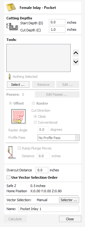
The Female Inlay - Pocket form offers all the same functionality of the Pocket Toolpath Form, but will automatically radius vector corners to account for the radius of the tool used for Inlay cutting. See the Pocket Tool documentation for more details.
Vector Selection Mode
When the Vector Selection Tool is chosen, the selected vectors are shown as dotted magenta lines. Vectors need to be selected before any of the editing tools such as scaling and moving etc. can be used.
Vector selection methods
Multiple vectors can be selected in the following ways:
- Manual multiple selection:
Hold down the Shift key while clicking the Left mouse button on each vector required. Objects can be deselected by simply clicking on the object again with a Shift key pressed. - Moving the cursor from Left to Right selects only fully enclosed objects:
Click and drag the left mouse button moving from Left to Right selects all objects completely inside the selection rectangle. - Moving the cursor from Right to Left selects all objects inside or touching the selection rectangle:
Click and drag the left mouse button moving from Right to Left selects all objects inside the selection rectangle + any that the selection touches. - Pressing the keyboard keys Ctrl+A will select all vector objects in the design:
Selected vectors are displayed as dotted magenta lines.
Deselecting Vectors
Selections can be cancelled by:
- Left clicking on an area outside the selection
- Pressing the Esc key
- Pressing the Right mouse button and clicking Selection ► Unselect All from the pop-up menu.
You must click on the white drawing background to get this option in the pop-up menu.
Migration Dialog
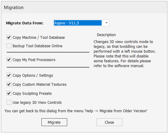
This tool helps existing users migrate their data from an older installation into the new version. You can migrate things like the Tool Database, Post-Processors in My_PostP, Options and various Defaults.
- Copy Machine / Tool Database; This will migrate your tool database and machines and the post-processor associations. You can check the data from the Tool Database and Machine Configuration dialogs.
- Backup Tool Database Online; This will back up the new tool database (just migrated) to your online tool database backup area for the new version.
- My Post Processors; This will only copy your custom Post Processors in My_PostP folder.
- Options; Copy most of the options on Options Dialog.
- Custom Material Textures; For use in simulation and job setup.
- Sculpting Presets; Only in Aspire for use in the Sculpting tool.
- Use Legacy 3D View Control; This allows you to retain the ability to move the 3D View using the left mouse button as seen in V11.5 and older software, and not use the new V12 3D control options.
Note
If the Legacy 3D view control is selected then some features in the 3D view will not be available. This can be changed later in the Program options by going to Edit -> Options.
Toolpath Tabs
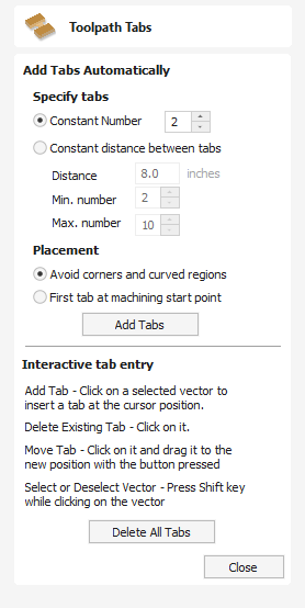
The tab placement dialog allows you to place tabs either automatically or dynamically.
Add Tabs Automatically
Automatically place the tabs by setting the Tabs options and clicking the button
Specify Tabs
There are 2 options:
- Constant number - Attempts to add the specified number of tabs by distributing them evenly along the vectors.
- Constant distance between tabs - Attempts to add tabs at regularly spaced distances.
Placement
There are two options for placement of tabs. The first tab can be placed at the machining start point, using the corresponding option. Otherwise, the Avoid corners and curved regions option can be used. This option will try to avoid placing the tabs at corners, whilst still trying to use the options above which specify the number of tabs and the distance between them.
Note
It may not always be possible to avoid all corners, whilst trying to place the chosen number of tabs and have them spaced relatively evenly.
Interactive Tab Entry
You can interactively add tabs by clicking in the 2D view.
Add Tab
Click on the vector where no tab exists to insert a new tab.
Delete Tab
Click on an existing tab to delete it.
Move Tab
Click on the tab and drag to move it along the vector into the new position.
Delete All Tabs
Click the button to delete all of the tabs.
VCarve Inlay Toolpath - Plug
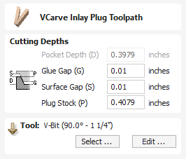
When Editing the Plug part of a VCarve Inlay toolpath, you will be presented with a slightly different form from the original toolpath.
Many of these options will function in the same way as its Parent toolpath form, with the following exceptions.
Pocket Depth (D)
This option is Greyed out and is locked from the orignal generation of this toolpath. If you need to adjust this setting, you need to delete both parts of the Inlay toolpath and remake the VCarve Inlay.
Plug Stock (P)
This is the thickness of material which will be left on the back of the Plug , and is automatically derived from the Pocket Depth (D) + Glue Gap (G) and cannot be adjusted on its own.
If you are Pocketing the back of the plug off once the Inlay is Glued in and cannot reference Z Zero from the original Inlays Surface, then Set Z Zero to the back of the Plug, and create a Pocket toolpath with a Cut Depth equal to this Plug Stock (P) Value to remove the back of the Plug.
Calculation Edit Boxes
Numerical edit boxes generally support simple calculations.
A sum can be entered directly into the edit box:
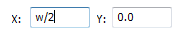
Having typed an equation, pressing the = key will perform the entered calculation and fill the edit box with the answer.
Special Calculation Characters
As well as the simple numerical calculations, such as 3+(4/5), several of Aspire's stored values can be accessed by using certain letters (which are not case-sensitive): When used, Aspire substitutes the character with the appropriate value in the calculation.
Character | Name | Example | Description |
|---|---|---|---|
W or X | Material Width |
| Half of the material width |
H or Y | Material Height |
| Twice the height of the material |
T or Z | Material Thickness |
| 0.25 units less than the material thickness |
P | PI (3.141593) |
| Area of a 10 radius circle (π.r2) |
I | Imperial Conversion |
| Converts 25.4mm to inches |
M | Metric Conversion |
| Converts 2 inches to millimetres |
' | Feet |
| 34 inches (2 feet and 10 inches) |
Add Draft to Model
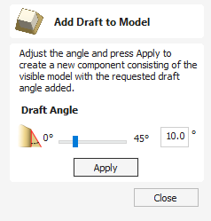
For some applications it can be useful to eliminate vertical walls on 3D models, especially if the machined part is intended to be used as the basis for a mold or vacuum forming tool.
The Add Draft tool will automatically add a minimum angle to any steep walls that exist in your model. The draft angle is specified by using the slider or entering a typed value in the form.
When the button is pressed, the tool creates a new 3D Component by baking the visible Components and applying the draft angle across all the walls of the composite model. Note that you do not select the Component/s to apply the draft angle to, just ensure that they are visible in the 3D view. The resulting Component will not have any wall angles that are steeper than the specified draft angle. Once complete, both the original Component/s and the new Component will be visible, although the original may be obscured by the new Component. The Component with the draft angle will be named appropriately indicating the amount of draft that was added. The images below show how a Component looks before and after adding 20° of draft.


Note
If you are creating a model within a two sided environment the draft will only be applied to the side you are currently working on. To apply a draft to both sides you will need to switch over to the opposite side and apply a draft to the model there.
Transform Mode
Use this to select an object in the 2D or 3D View to show its Interactive Selection Transform Handles.
Watch this video to see this in action:
Usable In Both Views
This tool can be used in both the 2D and 3D View.
2D View offers a more direct way to view your vectors while 3D Offers more flexability to work with Vectors in 3D Designs and to make use of the Edit Boxes.
Import a Component or 3D Model
This command opens the File Open dialog window, and in Aspire allowing existing files (CRV3D extension for Aspire and CRV extension for VCarve) and importable 3rd party 3D files to be selected and opened. If you select a 3rd party 3D model format, the Orientate Model form will open (see below) to allow you to manipulate the 3D model before it is converted into a Component.
In VCarve Pro and VCarve Desktop, it allows for importable 3rd party 3D files to be selected and opened.
CRV3D | Note Aspire Only 3D data from files previously created and saved in ASPIRE will be opened and a new single Component Created (from all the visible 3D Components in the file when it was saved). The new Component will have the same name as the file. This will be imported at the size and position the part was saved in the original file. |
3DCLIP | Note Aspire Only 3D Clipart files are exported from Aspire. This format maintains the component structure of clipart pieces at the time of saving, so will import all the components comprising the clipart piece. This will be imported at the size and position the part was saved in the original file. |
V3M | V3M is a proprietary file format developed by Vectric for Vector Art 3D and Design and Make. Files in this format can be purchased from www.vectorart3d.com and www.designandmake.com and when imported into Aspire will create a new Component with the same name as the file. This will be imported at the size and position the part was saved in the original file. |
STL | This is a standard format for complex 3D models, based on a triangular mesh. STL files can be exported from many 3D design software programs such as Rhino. These models can be completely 3 dimensional (i.e. have a front, back, etc.), this means that when this type of file is opened that it must first be sized and oriented before a Component can be created (Aspire only represents base-relief so cannot work with a completely 3D object). Once the file becomes a Component it will have the same name as the original STL file. This file type will need to be imported using the Orientate 3D ModelAspire. |
DXF | 3D DXF files from AutoCAD and many other CAD orientated modeling packages, these must be 3D meshes and not just wireframe data of the models vertices. This file type will need to be imported using the Orientate 3D ModelAspire. |
3DS | A native format from 3D Studio Max and many other animation orientated modeling packages. This file type will need to be imported using the Orientate 3D ModelAspire. |
OBJ | A native format from Wavefront and many other animation orientated modeling packages. This file type will need to be imported using the Orientate 3D ModelAspire. |
SKP | A native format from the SketchUp modeling package. This file type will need to be imported using the Orientate 3D ModelAspire. |
Note
If you wish to read data from a 3D digitizer or scanning device then STL is typically the best format that should be used to import the data. Many software packages that work with a scanner offer an STL export option, if not then a third party software program may be required to convert the data to an STL model.
Importing a 3D Model (STL, DXF, 3DS, OBJ, ...)
When one of these formats are chosen for 3D file Import, the imported model needs to be oriented and scaled before it can become a Component. A special import window is opened and a set of orientation/scaling tools enabled. Depending on the job type, import window will be different:
Re-Importing
Once a 3D Model has been imported then provided it has not been changed significantly it is possible to re-import the model to adjust the size, position, and slicing plane of the imported model. To re-import right click one of the components for the imported model in the component tree and select
If the new segmenting feature has been used then reimporting will open up the 3D segment dialog to its last know state for the model, allowing you to make a small adjustment and then reimport.
File Types
CRV3D | Files previously created and saved in Aspire will be opened and displayed in the 2D Design window and 3D View if they contain 3D data. All calculated toolpaths are stored/opened from the CRV3D file. This format is only compatible with Aspire |
CRV | Files previously created and saved in Aspire will be opened and displayed in the 2D Design window. All calculated toolpaths are stored/opened from the CRV file. |
CRVT CRVT3D | Template files previously created and saved in Aspire will be opened and displayed in the 2D Design window and 3D View if they contain 3D data. All calculated toolpaths are stored/opened from the CRVT/CRVT3D file. CRVT3D is only compatible with Aspire |
DXF | Files from other CAD or graphics software packages such as AutoCAD will be opened in the original size and position. The Job Setup Form is automatically opened showing the maximum X and Y dimensions of the opened design. The actual size of the material can then be specified along with the required thickness and appropriate X0, Y0 and Z0 origins. |
EPS | Files from typical design software such as Corel Draw can be opened. The Job Setup form will automatically be opened so the required material size can be specified. By default the EPS file will be placed with the lower left corner of the design at X0, Y0. |
AI | Files from typical design software such as Adobe Illustrator and Corel Draw can be opened. The Job Setup form will automatically be opened so the required material size can be specified. The AI file will be placed with the lower left corner of the design at X0, Y0 |
Software such as the Adobe product range can be used to convert files from other design and word processing software into the industry standard PDF file format. The text and vector content of PDF files is extracted when imported into Aspire. When importing multiple page PDF documents each page is placed on a separate layer. | |
SKP | SketchUp files with a .SKP extension (see www.sketchup.com) can be imported as 2D data suitable for machining. |
Smooth Components
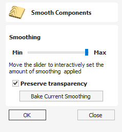
Often it is advantageous to apply a general smoothing effect over the whole of a component (rather than smooth a particular area with the Sculpting Tools). To use this tool, select the components you wish to smooth and then click the Apply smoothing filter to selected components icon on the Modeling tab. The form will appear and Aspire will take a few seconds to prepare the model for the smoothing operation. You will see a progress bar at the bottom of the screen while it is doing this.
One or more Components can be selected for Smoothing. If you select multiple shapes or a Component Group then the software will need to Bake your selection into a single Component, if applicable you should ensure you have a safe copy of your current Components before proceeding.
If you wish to smooth individual components one after another, potentially with different amounts of smoothing, you can do this by selecting one component, apply a suitable smooth filter value with the slider and then hit the Bake Current Smoothing button in the form and then proceed to selecting the next component you wish to smooth. When pick a new Component the software may take a few seconds to pick it and apply the smoothing filter to it at the default of 50% strength. If you do not click on the button before you select a new component then the effects of the smoothing will be lost on the previously selected component.
Note
Smoothing should be performed with both the 2D and 3D View visible (Tile Windows), so you can easily see the selected Component in the 2D View and also view the effects of the smoothing in real time on the 3D model in the 3D View.
Smoothing
This slider will allow the user to control the strength of the smoothing applied to the Component. By default 50% smoothing is applied, using the slider different levels of smoothing can be applied to the model. Find the strength which gives you the amount of smoothing you require. If the Max setting has not smoothed the model enough then hit the Bake Current Smoothing button which resets the smoothing slider to allow you to do further smoothing.
Preserve Transparency
Checking ✓ this option will keep the smoothing only on the current 3D areas of the selected shapes and not smooth the edges into the background. Un-checking this option will smooth all the edges of the modeled area into the background of the part, blurring the silhouette of the Component.
Bake Current Smoothing
The button bakes the current smoothing value into the Component and resets the form. This means you are able to perform multiple smoothing operations without leaving the function.
07. Intermediate - 3D Design and Management
As well as creating toolpaths directly from 2D drawings, Aspire can produce extremely flexible 3D toolpaths. These toolpaths are created from 3D design elements called 3D Components that can be generated from models created in external 3D design packages, imported as 3D clipart or built entirely from within Aspire using 2D artwork as a source.
The 3D View
The 3D View can show you the current Composite Model (which is built from all of the currently visible 3D Components and Levels), the Toolpath Preview (a highly accurate 3D simulation of the resulting physical object that will result from your toolpaths called the Preview Material Block). Which of these is currently displayed will depend on whether or not you have a part which has 3D Components and Toolpaths or are just working on something that only includes 2D Data.
Whenever you have the Preview Toolpaths form open on the Toolpaths tab, the 3D View displays the Preview Material Block instead of the Composite Model. When this is closed if you are working on a part that only includes 2D data and 2D or 2.5D toolpaths it will continue to display the Preview Material Block. If your part contains any visible 3D Components then as soon as the Preview Toolpaths form is closed it will revert to showing the Composite Model in the 3D View and hide the simulation. In addition to these items, you can see line drawings of any calculated toolpaths in the 3D View. The visibility of these calculated toolpaths can be controlled from the Toolpath List on the Toolpaths tab using the check-boxes next to the toolpaths name. If working in a 2 Sided environment you can view both sides of a project in the 3D View using the Multi Sided View option.
The Composite Model
Aspire has been designed to work in a way which enables the user to easily create even very complex projects. In any situation, the best approach to producing something complicated is to break it down into smaller pieces until a level of simplicity is reached that can be understood and managed. In Aspire this is achieved by letting the user work with pieces of the design which are combined to make the finished part. In the terminology of the software these pieces are called Components. To help organize the Components they are assigned to Levels. Step by step, Components and Levels can be created and modified until you have all the elements you need. In the images below you can see an example of how this might work. On the left you can see the separate component for a model of a bunch of grapes and on the right you can see these positioned to make the complete part - we call this resulting combination the Composite Model.
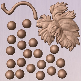
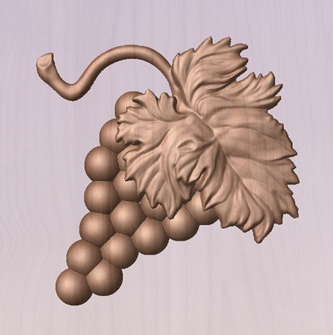
There is no limit to how simple or complex a Component or the Components on a Level can be (this is the user's choice). In the example shown, you can see that a model of a whole bunch of grapes may be made up of smaller individual components but they could also be combined to exist as one single Component (the assembled bunch of grapes) that could then be used to lay-out a more complex part with multiple bunches of grapes. They could also be organized so all the grapes were on one Level and leaf and stem on another to provide a different way of managing and manipulating the shapes. Each user will find a level of using Components and Levels they are comfortable with which may be dependent on the particular job or level of proficiency with the modeling tools.
3D Components and Levels
In Aspire, the aim is to end up with a set of Components and Levels that when combined together will make the finished 3D part. One way to think of this is like building a 3D collage or assembly. As the design evolves, new Levels or shapes may need to be created or existing ones changed. The parts of the collage are managed with the Component Tree which will be covered in more detail later.
Creating and Editing Components
An existing Component can be copied, scaled and have other edits carried out on it as an object. The user can also change the way it relates to the other Components, for instance whether it sits on top or blends into an overlapping area of another Component. The shape, location and relation of these pieces determine the look of the final part. As the job progresses, the user will need to create brand new Components or edit existing ones by adding new shapes, combining them with others or sculpting them.
Components can be created and edited by:
- Use a modelling tool to create shapes from 2D vectors.
- Import a pre-created 3D model - either a model previously created in Aspire or from another source such as a clipart library or a different modelling package.
- Create a 'texture' Component from a bitmap image.
- Use the Split Components Tool to break an existing Component into multiple pieces.
All of these methods are covered in detail throughout the training material.
Dynamic Properties
As well as having its underlying 3D shape, each component also has a number of dynamic properties that can be freely modified without permanently changing its true shape. These include scaling of the Component's height, the ability to tilt it, or to apply a graduated fade across it.
These dynamic properties can always be reset or altered at any time during your modeling process, which makes them a particularly useful way of 'tweaking 'your components as you combine them together to form your final composite model.
Combine Modes
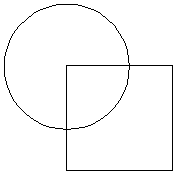
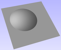
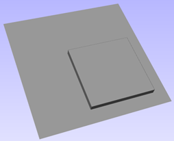
The Combine Mode is a very important concept when working with 3D shapes within Aspire. The options for combine mode are presented when creating new shapes and also when deciding how Components and Levels will interact in the Component List. Rather than cover this in every section where it is applicable, it is worth summarizing the options here so the general concept can be understood.
When you have more than one 3D shape, such as the Component pieces of the design or where you have an existing shape and are creating a new one, then you need to have a way to tell the software how the additional entities will interact with the first. This can be an abstract concept for users who are new to 3D but it is an important one to grasp as early as possible. In Aspire this is controlled by a choice called the Combine Mode.
There are four options for this: Add, Subtract, Merge High, Merge Low.
As modeling is an artistic and creative process, there is no general rule to describe when to use each one. As a guide though you can assume that if the second shape's area is completely within the originals one then you will probably be adding or subtracting and if the shapes only partly overlap that you will probably use Merge or, very occasionally, Low.
The four options and their specific effects are described on the following pages. To illustrate the different effects a combination of an overlapping beveled square and a dome will be used. You can see in the image top right how these are arranged in the 2D View and how they overlap. Then you can see each individual shape in the images below middle and right. These shapes will be used to demonstrate the different Combine Modes. In every case the Dome will be considered the primary shape and the square is the secondary shape which is being combined with the first. In addition to the dome/square example some images of 'real world' parts will also be included to help to understand how these can be used on actual projects.
As well as working on individual shapes, the Combine Modes are also assigned to Levels. These will govern how the combination of all the individual components on one Level interacts with the result of all the Components on the Level below it in the Component Tree
Note:
There is a 5th Combine Mode available from the right mouse click menu after a component has been created called Multiply. This combine mode has specialist applications which are dealt with in the appropriate tutorial videos. This option will literally multiply the heights of the Component or Levels being combined to create the new Composite 3D shape.
Add
When Add is selected, it takes the first shape and then just adds the height of the second shape directly on top of the first. Any areas which overlap will create a shape which is exactly the height of each shape at that point added together (see below)
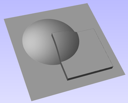
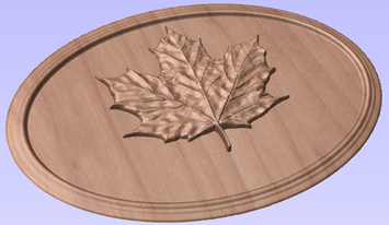
Typically the add option is mainly used when the shape being added sits completely within the original shape, this ensures that the uneven transition where the parts only partly overlap (as shown in the example) do not occur.
The example above shows the Maple Leaf and border extrusion Components being Added to the dome Component in the sign example from the Introduction to Modeling document.
Subtract
When Subtract is selected it takes the first shape and then removes the height of the second shape from the first. Any areas which overlap will be a combination of the original height/shape less the second shape. Areas where the shape goes into the background will become negative regions. You can see how this looks using the dome and square in the image below:
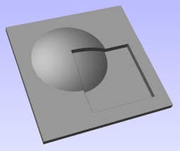
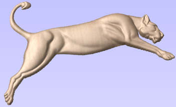
Typically subtract, like the add option, is mainly used when the shape being removed sits completely within the original shape, this ensures that the uneven transition where the parts only partly overlap (as shown in the example) do not occur.
The image shown above has some 'creases' to help define the muscles of the lioness. The shapes to create these recesses were created by using the Subtract option with the Create Shape tool on the vectors representing those recessed areas.
Merge
When the Merge option is selected any areas of the shapes which do not overlap remain the same. The areas that overlap will blend into each other so that the highest areas of each are left visible. This results in the look of one shape merging into the other and is in effect a Boolean union operation. You can see how this looks using the dome and square in the image below:
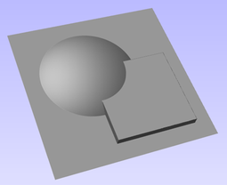
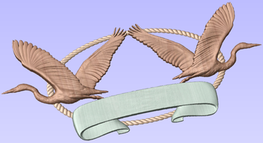
Typically the merge option is used when the shape being combined partly overlaps the original shape. This enables a reasonable transition to be made between them.
The image above shows 2 Herons, a rope border and banner Components. Each of these overlaps with the others and so they are set to Merge in this areas. Whatever is the higher of the two merged areas is what is prominent. In this case the rope is lower than everything and the Banner is higher than the Herons so the desired effect can be achieved.
Low
The Low option is only available when combining Components (not in the modeling tools). When this mode is selected, any areas which do not overlap are left as they were in the original two shapes. Any areas which overlap will create a new shape which is the lowest points taken from each shape, this is in effect a Boolean intersection operation. You can see how this looks using the dome and square in the image below:
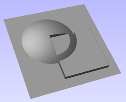
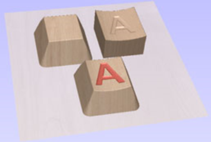
The Low option is used for recessing a shape into a raised shape. An example of this is shown in the image above.
The example shown on the right above uses the Low option to combine the flat topped 'button' component on the left with the curved top face component with the letter 'A' on the right. Combining both components with the merge low option gives the keyboard button with the curved top you see in the bottom row.
Level Mirror Modes
Right-clicking Levels in the component tree will open a pop-up menu offering commands and operations related to the clicked level and Mirror Modes can be set in this way. If a mirror mode is set on a Level, all the components it contains will be continually mirrored dynamically as they are moved, transformed or edited. The mirroring is non-destructive, that is it can be turned off or on at any time and does not alter the underlying components in any permanent way. Working inside a Mirror modes Level is a simple way of achieving a complicated symmetrical pattern by editing only one half (or quarter, see below) of the design.
The available Mirror Modes are broadly divided into two groups. The first group apply one plane of symmetry:
- Left to Right
- Right to Left
- Top to Bottom
- Bottom to Top
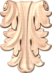
These modes allow you to work in one half of your job and the other half will be automatically and dynamically generated for you. For example, in Left to Right mode you would place your components in the left half of your job and a mirrored equivalent of each would be created in the other half of the job. This 'reflection' is updated dynamically as you work.
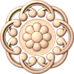
The other group offer two planes of symmetry (horizontal and vertical):
- Top Left Quadrant
- Top Right Quadrant
- Bottom Left Quadrant
- Bottom Right Quadrant
When using these modes your components should all be in the quadrant (quarter) of the job. Mirrored reflections horizontally and vertically will be created in the other quadrants of the job for you.
Watch this video to see this in action:
Multi Sided View

When working in a 2 Sided environment you can create components independently per side or using the Right click option you can copy or move a component to the opposite side. Selecting the option to work in 'Multi Sided View' allows you to view components you may have on the Top and Bottom side in the 3D View. In the Toolpath Preview form of a project that contains toolpaths for the Top and Bottom Sides the multi sided view presents the simulation of the toolpath preview on both sides also, if the multi sided view is not selected you can use the 'Preview all Sides' option in the Toolpath Preview form to display the Top and Bottom Toolpaths in the 3D view. 2 Sided Setup will be described in detail later in the relevant section of this manual.
Kickstarter Wizard
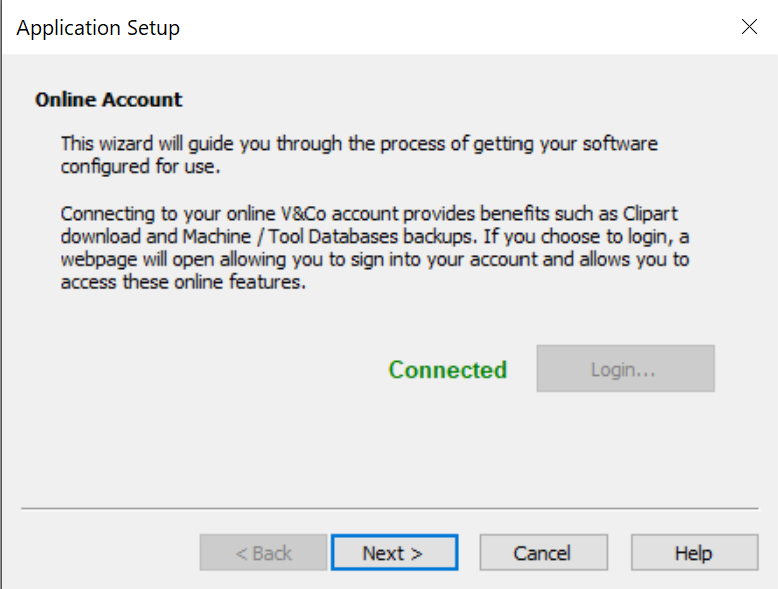
The Kickstarter Wizard is provided to assist with the selection of a machine configuration, when you first use the software.
You can access the Kickstarter wizard at any time, by selecting Help > Kickstarter Wizard from the main menu bar of Aspire
The wizard has multiple pages to take you through,
- Signing in
- Registering your Aspire software in V&Co
- Looking for your machine online
- Manual configuration of your machine
Sculpting
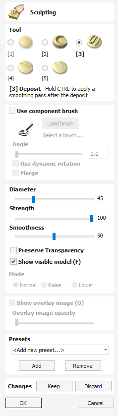
The Sculpting function in Aspire is a very powerful way to edit (or create) 3D shapes. It allows the user to perform truly dynamic interactive editing of 3D Components. Once activated, the user chooses from a variety of tool options which determine how the model will be changed and then uses the mouse (or a pen tablet) to actually edit the 3D model. This is done in the 3D view and requires the user to click and move the mouse cursor in the area of the model they want to apply the tool. The best way to understand this tool is to actually try it and to watch the Tutorial Videos that are supplied with the software as it is very much a visual tool (which is what gives it its power).
Watch this video to see this in action:
One or more Components can be selected for Sculpting. If you select multiple shapes or a Component Group then the software will need to Bake your selection into a single Component, if applicable you should ensure you have a safe copy of your selection before proceeding.
In addition to components, you can also select bitmap. The bitmap will be overlaid on the sculpted model. This is useful when sculpting based on the photo.
View Control while Sculpting
While the Sculpting tool is active, the 3D View controls are slightly altered.
- Panning is achieved by Clicking and Holding the middle Mouse Button, while dragging the Mouse.
- Zooming in and out is done the holding the ALT Key and scrolling the mouse wheel back and forward.
- Tilting the 3D View is managed by clicking and dragging the Right Mouse Button.
Tool
One sculpting tool at a time can be selected by clicking the option from the form or using the shortcut keys (numbers 1-5 displayed next to each option):
Smooth
As the user moves the mouse back and forward over the 3D model the area under the red cursor will be smoothed out to average the high and low areas of the model.
Smudge
As the user moves the mouse from one place to another on the 3D model the material under the red cursor will be dragged, similar to smudging a piece of clay with your thumb. In Aspire it means that going from a high to low will pull the higher material into the lower and vice-versa.
Deposit
As the user moves the mouse over the 3D model the area under the red cursor will have material added to it to increase its height.
Remove
As the user moves the mouse over the 3D model the area under the red cursor will have material removed from it to decrease its height.
Undo Brush
As the user moves the mouse over any area of the 3D model that has already been sculpted then the area under the red cursor will be gradually returned to its original state. This can be used to undo some of the sculpting if you make a mistake.
Note
If you press the 'shift' key with the Undo Brush selected you can erase the section of the model under the cursor completely, this is a useful way to tidy up the edge of a shape or delete specific parts of a component.
Alternately you can use the Key combination Ctrl+Z to undo the last move that you made without using the Undo Brush.
Custom Brush
Rather than the usual circular brush a custom brush made from any model can be used when in deposit or remove modes. The brush will leave an impression that simulates the pushing of the model through the surface. This technique can be used to add detail and texture to models.
Watch this video to see this in action:
Creating a brush
The custom brush mode can use any .3dclip, .v3m or bitmap as the custom brush. However it is usually best to use a model that has been created specifically for the role of a custom sculpting brush. To create such a brush, right-click on the model in the component tree and choose Create sculpting brush. The brush will be created, optimized for use in sculpting, and placed in the standard location for sculpting brushes to allow easy access from withing the sculpting form.
Selecting a brush
To select a brush click on the Load Brush button and choose the desired model or bitmap
Angle
The angle slider and associated edit box are used to set the current rotation of the brush. If dynamic rotation is not checked then this rotation angle will be fixed. The angle can be adjusted by holding down the r key and scrolling the mouse wheel.
Dynamic Rotation
If the use dynamic rotation option is checked then as the brush is dragged during sculpting the current rotation of the brush will be updated to follow the stroke of the brush.
In the 3D view a small arrow is shown indicating the current rotation of the brush.
Merge
The Merge checkbox controls whether the result of on sculpting stroke is merged with the previous strokes, or is added onto it.
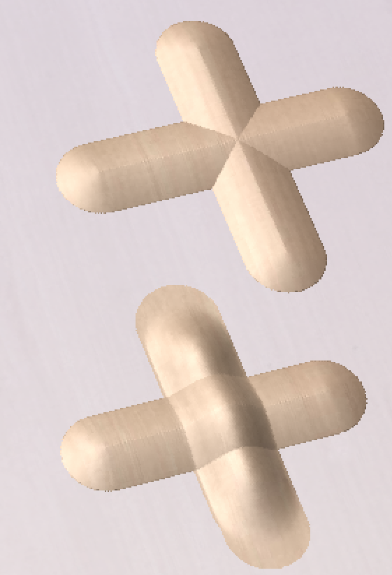
Constraining Sculpting
To constrain sculpting to be either absolutely vertical or horizontal then hold down the v or h key when sculpting.
Note
The vertical and horizontal here are relative to 3D view and not to the model itself.
Diameter
This slider will allow the user to control the size of the sculpting cursor (red circle). This value can also be changed while sculpting by rolling the 'wheel' on a roller mouse, pressing control while rolling the wheel will change the diameter in smaller increments.
Strength
This slider controls the strength of the tool that is currently selected. The higher the strength the more effect the tool will have as the cursor is moved over the model. The strength can also be adjusted by rolling the mouse wheel while pressing the Shift key if you have a roller mouse.
Smoothness
This slider controls how smoothly the selected tool will manipulate the model. A higher smoothness setting will create a more gentle transition while a lower smoothness setting will create a jagged and potentially distorted effect.
Preserve Transparency
This option is checked ✓ by default when you first go into the Sculpting. Leaving it checked ✓ will mask the sculpting so it is only applied within the existing boundary of the component. This stops the edges being blended into the background. It is called Preserve Transparency as the background is represented by a transparent (lighter colored) flat plane around the edge of the 3D component. Un-checking this option allows the user to sculpt the part into the modeling plane if the shape needs to be changed to go outside of its original edge or if the edges need smoothing into the background. Pressing the 0 key while sculpting is a shortcut to toggle this option.
Show Full Model (G)
This option makes any surrounding components which may be included in the full composite model also visible in the 3D view, whilst sculpting tools are still only applied to the selected component.
Mode
The sculpting mode defines how the tool is applied to the model in terms of the heights of the shape under the sculpting cursor. The Raise option is good for filling in holes and the Lower option is good for eliminating spikes in a model. A good example of need for this may be if the user was working with 3D digitized data which had been imported from a scanner (e.g. as an STL model).
Normal
Selecting this option means that the sculpting operation will average the high and low points under the cursor dragging them up or down as appropriate.
Raise
Selecting this option will maintain the highest points under the cursor when smoothing or smudging only allowing material to be added (based on the currently selected tool).
Lower
Selecting this option will maintain the lowest points under the cursor when smoothing or smudging only allowing material to be removed (based on the currently selected tool).
Overlay Image
If bitmap is selected when opening this tool, it will be overlaid on the sculpted model.
Overlay image opacity
Controls how translucent the overlaid image is.
Show overlay image
Allow to quickly toggle between overlaid image being visible or not. This allows the user to work with overlaid image hidden and only displayed periodically to guide the sculpting process.
This option can also be accessed by pressing the O key.
Presets
Selecting a preset from the drop down list will restore the sculpting tool settings previously stored within it. This is a quick way of switching between commonly used settings. Selecting <Add new preset...> from the list is an alternative way to create a new preset.
Add
Clicking the button will save the current sculpting tool settings in a preset. You will be prompted to enter a name for the preset. If a preset with the same name for the same tool type already exists then you will be asked if you would like to overwrite it.
Remove
Clicking the button will remove the preset currently displayed in the drop down list.
Changes
Sculpting is a very iterative process and frequently as the user progresses, they will want to either get rid of a recent change, or will want to save the changes they have made and continue sculpting. The options under Changes in the form allow the user to do this.
Keep
Clicking the button will internally save the sculpting changes made so far. This should be clicked if the user is happy with the sculpting so far and wants to keep it but also wants to continue to sculpt the model.
Discard
Clicking the button will discard all the changes made with the sculpting tools back to the stage that the Keep button was last clicked. If the Keep button has not been clicked within a particular sculpting session then all the changes will be discarded. In order to ensure that this is not accidentally selected a Warning will appear giving you the option to verify you want to discard your changes. This warning can be bypassed by holding down the Shift key while pressing Discard.
OK
Clicking will accept all the changes made to the model within the sculpting session and exit the form updating the Component Tree with the newly sculpted model.
Cancel
Clicking will exit the sculpting and discard ALL the changes you made within that sculpting session. The changes will be discarded even if you have previously hit Keep. If you wanted to keep most of your changes but discard just the ones you made since the last Keep then you should hit first then . In order to ensure that this is not accidentally selected a Warning will appear giving you the option to verify you want to exit and discard ALL your changes. This warning can be bypassed by holding down the Shift key while pressing .
15. Advanced - Post-Processor Editing
What does the Post Processor Do?
The post processor is the section of the program that converts the XYZ coordinates for the tool moves into a format that is suitable for a particular router or machine tool. This document details how to create and edit the configuration files that customize the output from the program to suit a particular machine control.
Below are sections of a typical program that has been post processed into both G-Code and HPGL
G-Code Output
T1 M6
G17
G0 Z4.5000
G0 X0.0000 Y0.0000 S12000 M3
G0 X2.4567 Y7.8342 Z0.2500
G1 Z-0.0500 F5.0
G3 X3.3784 Y8.7559 I0.0000 J0.9218 F66.0
G3 X2.4567 Y9.6777 I-0.9218 J0.0000
G3 X1.5349 Y8.7559 I0.0000 J-0.9218
HPGL Output
IN;PA;
PU2496,7960;
PD2496,7960;
AA2496,8896,90.000
AA2496,8896,90.000
AA2496,8896,90.000
AA2496,8896,90.000
PU2496,7960;
PU2496,6096;
Machine controller manufacturers will often customize the file format required for programs to run on a particular machine in order to optimize the control to suit the individual characteristics of that machine.
The Vectric post processor uses simple text based configuration files, to enable the user to tailor a configuration file, should they wish to do so.
Post Processor Sections
Vectric post processors are broken down into sections to aid clarity, try to write your post processors in a similar style to aid debugging.
File Comments
A section where you can describe the post processor and record any changes to the post processor, each line is a comment and starts with a ‘+’ character or a ‘|’ character.
+ History
+ Who When What
+ ======== ========== ===========================
+ Tony 14/07/2006 Written
+ Mark 26/08/2008 Combined ATC commands, stop spindle on TC
+================================================
Global File Statements
Statements are items that are either used only once, or have static values throughout the file. Write statement names in upper case letters for clarity.
Statement | Result |
|---|---|
| The name that will appear in the post processor list |
| The file extension that the file will be given |
| The units that the file outputs (INCHES or MM) |
| The machine tool manufacturer has supplied a driver (usually a printer driver) thatn can directly accept the NC file output (For example see Generic HPCL_Arcs.pp) |
| Indicates that plunge moves to Plunge (Z2) height (that is set on the material setup form) are rapid moves |
| The control software uses a document interface that can directly accept the NC file output. |
| The moves in the Y axis are to be wrapped around a cylinder of the specified diameter. The "Y" values will be output as "A" |
| The moves in the X axis are to be wrapped around a cylinder of the specified diameter. The "X" values will be output as "B" |
| Spindle speed for this machine is output as a range of integer numbers between 1 and 15 representing the actual speed in RPM of the spindle, (between 4500 and 15000 RPM in the quoted example). For an example, see the file: Roland_MDX-40_mm.pp |
| This command allows you to substitute a character output within the variables (such as The characters are entered in pairs, Original - Subsititued. For example MACH 3 control software uses parentheses as comment delimiters, and does not allow nested comments. Most tools within the Vectric Tool Database have parentheses within the “Name” section; if these names are output, this would cause an error within Mach3. The command |
| Rotary: Enables / Disables output of the feedrate F in Inverse Time Feed Mode. In this mode, we're expected to complete a move in one divided by the F number of minutes. In GCode, this would usually be a G93 to switch on Inverse Time Mode, or a G94 to set Units per Minutes mode. |
| Indicates that this post-processor supports laser toolpaths (if the Laser Module is installed). |
| Optional minimum arc radius. Arcs which have a radius smaller than this value will be replaced with a single straight line move. |
| Optional maximum arc radius. Arcs which have a radius greater than this value will be polygonized. |
POST_BASE | This is a no longer supported way of inheriting the content of another post-processor. See the POST_BASE Migration page for more details. |
Tape Splitting Support
A section that describes how a long toolpath output will be split:
TAPE_SPLITTING=MAX_NUM_LINES LINE_TOL "FILENAME_FORMAT" START_INDEX INDEX_ON_FIRST_FILE
For example a command of:
TAPE_SPLITTING=1000 100 "%s_%d.tap" 1 "YES"
would lead to...
Output will be split into multiple files of a maximum of 1000 lines (+ however many lines in there are within the footer section of the post processor), if a retract move exists after line 900 (1000 – 100), the file will be split at that move. If the file was called "toolpath" the split files would be named toolpath_1.tap, toolpath_2.tap etc. The first toolpath output will be "toolpath_ 1.tap" there will be no file named "toolpath" without an index number, (as INDEX_ON_FIRST_FILE=YES is used), unless the file was less than 1000 lines long, in which case the file would not be split.
Note
Some controllers that require NC files to be split, also have limitations on the number of characters within a filename. For example they may require the file to be named with the MSDOS style 8.3 filename format. This should be considered when naming the output file.
Line Terminating Characters
LINE_ENDING="[13][12]"
Decimal values of the characters appended to each separate line of the post processed file. (Will usually be [13][10]) (Carriage return, line feed) for any controller that can read a windows or MSDOS format text file.
Block Numbering
If you wish to add line numbers to the output file, the current line number is added with the variable [N]. The behaviour of this line number variable is controlled by the following variables:
Statement | Result |
|---|---|
| Value at which the line numbering should start |
| Incremental value between line numbers |
| The maximum line number to output, before cycling to the Important - Some controllers have a limit to the number of lines that can be displayed on the control |
Variables
Variable Name | Output using | Value | Example File |
|---|---|---|---|
|
| Current Feed Rate. | Mach2_3_ATC_Arcs_inch.pp |
|
| Current Cut Feed Rate. | CNCShark-USB_Arcs_inch.pp |
|
| Current Plunge Feed Rate. | CNCShark-USB_Arcs_inch.pp |
|
| Current Spindle Speed in R.P.M. | GCode_arc_inch.pp |
|
| Current power setting for jet-based tools (e.g. lasers) | grbl_mm.pp |
|
| Current Tool Number. | Mach2_3_ATC_Arcs_inch.pp |
|
| Previous Tool Number. | NC-Easy.pp |
|
| Line Number. | Mach2_3_ATC_Arcs_inch.pp |
|
| Name of Current Tool. | MaxNC_inch.pp |
|
| Text from Note field in ToolDB for current tool | Busellato_Jet3006_arc_inch.pp |
|
| Name of Current Toolpath. | Viccam_ATC_Arcs_inch.pp |
|
| Filename (Produced by “Save Toolpath(s)”). | ez-Router_inch.pp |
|
| Folder Toolpath File was saved to. | Woodp_arc_mm.pp |
|
| Toolpath File Extension. | TekcelE_Arc_ATC_3D.pp |
|
| Toolpath Folder Pathname. | WinPC-NC_ATC_Arcs_mm.pp |
|
| Current coordinate of tool position in X axis. | GCode_arc_inch.pp |
|
| Current coordinate of tool position in Y axis. | GCode_arc_inch.pp |
|
| Current coordinate of tool position in Z axis. | GCode_arc_inch.pp |
|
| Current coordinate of tool position in A axis. | |
|
| Arc centre in X Axis (relative to last X,Y position). | Mach2_3_ATC_Arcs_inch.pp |
|
| Arc centre in Y Axis (relative to last X,Y position). | Mach2_3_ATC_Arcs_inch.pp |
|
| Arc centre in X Axis (absolute coordinates). | Isel_arc_mm.pp |
|
| Arc centre in Y Axis (absolute coordinates). | Isel_arc_mm.pp |
|
| Start position of an arc in X axis. | TextOutput_Arcs_mm.pp |
|
| Start position of an arc in Y axis. | TextOutput_Arcs_mm.pp |
|
| Mid-point of arc in X (absolute coordinates). | TextOutput_Arcs_mm.pp |
|
| Mid-point of arc in Y (absolute coordinates). | TextOutput_Arcs_mm.pp |
|
| Mid-point of arc in X (incremental coordinates). | TextOutput_Arcs_mm.pp |
|
| Mid-point of arc in Y (incremental coordinates). | TextOutput_Arcs_mm.pp |
|
| The radius of an arc. | Bosch_ATC_Arcs_mm.pp |
|
| The angle of an arc. | Generic HPGL_Arcs.pp |
|
| Home tool position for X axis. | CAMTech_CMC3_mm.pp |
|
| Home tool position for Y axis. | CAMTech_CMC3_mm.pp |
|
| Home tool position for Z axis. | CAMTech_CMC3_mm.pp |
|
| Safe Z Height / Rapid Clearance Gap. | EMC2 Arcs(inch)(*.ngc) |
|
| Diameter of cylinder that axis is wrapped around. | Mach2_3_WrapY2A_ATC_Arcs_mm.pp |
|
| Length of material in X. | Mach2_3_ATC_Arcs_inch.pp |
|
| Length of material in Y. | Mach2_3_ATC_Arcs_inch.pp |
|
| Length of material in Z. | Mach2_3_ATC_Arcs_inch.pp |
|
| Minimum value of material in X. | MaxNC_inch.pp |
|
| Minimum value of material in Y. | MaxNC_inch.pp |
|
| Minimum value of material in Z. | MaxNC_inch.pp |
|
| Maximum value of material in X. | MaxNC_inch.pp |
|
| Maximum value of material in Y. | MaxNC_inch.pp |
|
| Maximum value of material in Z. | MaxNC_inch.pp |
|
| Origin Position in X. | TextOutput_Arcs_mm.pp |
|
| Origin Position in Y. | TextOutput_Arcs_mm.pp |
|
| Z Zero Position, Table or Material Surface. | TextOutput_Arcs_mm.pp |
|
| X, Y Origin. | TextOutput_Arcs_mm.pp |
|
| List of tools used (In order of use). | Mach2_3_ATC_Arcs_inch.pp |
|
| List of toolpaths used in file (in order of use). | Mach2_3_ATC_Arcs_inch.pp |
|
| Toolpath Notes (Toolpath Control form). | Mach2_3_ATC_Arcs_inch.pp |
|
| File Notes (Edit > Notes). | Mach2_3_ATC_Arcs_inch.pp |
|
| File creation time. | Mach2_3_ATC_Arcs_inch.pp |
|
| File creation date. | Mach2_3_ATC_Arcs_inch.pp |
|
| Dwell time in seconds when drilling. | Mach2_3_Arcs_inch.pp |
|
| Name of the product used to output file, including version number. | |
|
| Tool diameter. | |
|
| Rotary: Current Inverse Time Rate | AvidCNC_WrapX2A_G93_inch.pp |
Format of Variables
Values for tool position, feed rates, spindle speeds etc. are inserted into the file using variables. Variables are used throughout the file; the variables are replaced with the current value for that item when the file is post processed. For example, the current X, Y and Z tool positions at any time, are inserted into the file by using the variable output, [X], [Y] and [Z] respectively.
Write variable names in upper case letters for clarity.
A Variable is formatted as follows:
VAR VARIABLE = [VO|WO|CS|VF|MX]
where
VO= Variable output for example X, XF or F.WO= When output, A=Always, C=Only when changed.CS= Character string output before value .VF= Value format, determines the format that the value is output with.MX= Multiplier Value.
A typical variable
1 | 2 | 3 | 4 | 5 | 6 | 7 | 8 | 9 | 10 | 11 | 12 | 13 | 14 | 15 |
|---|---|---|---|---|---|---|---|---|---|---|---|---|---|---|
|
|
|
|
|
|
|
|
|
|
|
|
|
|
|
VAR- This line is a Variable.- Variable Name.
- Equals Sign.
- Open Square bracket - (start of variable formatting parameters).
- Variable label - i.e. label that is substituted with the variable value.
- Vertical Bar - Parameter separator.
A= Always output value,C= Only output value when it changes- Vertical Bar - Parameter separator.
- Character string to print before variable value.
- Vertical Bar - Parameter separator.
- Optional Format Flags - for details see below.
- Value Format - units and number of decimal places to output.
- Vertical Bar - Parameter separator.
- Output multiplier - for details see below.
- Close Square Bracket - End of formatting parameters.
Formatting the Output Value
The values format string should be formatted as follows:
FORMAT_FLAGS FIELD_WIDTH DECIMAL_SEPARATOR DECIMAL_PLACES
The format flags are optional and only needed by a small number of controllers they will be described shortly.
Field Width The Field width represents the minimum number of characters that are output. The field width is usually set to “1” a value greater than 1 is typically only required if a controller expects to see a fixed number of characters for the value. If this is the case, a number greater than 1 can be entered. The number entered will ensure that that number of characters is output. The number that represents the field width includes the full floating-point number for the output value, (including the decimal separator character).
Decimal Separator The decimal separator character is almost always just a period character, but there are some controllers that expect to see a comma character. (For an example of a post processor that does not use a period character, see the file: Heidenhain_inch.pp)
Decimal Places The number of decimal places output following the decimal separator. The values are often set at 3 for controllers operating in Metric, or 4 for controllers operating in Inches.
Optional Format Flags
The output values can be further modified by using the optional format flags:
Flag | Function | Default (without flag) |
|---|---|---|
| Left Justify the output | Values are right justified |
| Prefix the value with '+' or '-' | Only negative values are prefixed |
| If value has fewer characters than the set minimum, the value is prefixed with zeroes | Values is prefixed with blanks spaces |
| Values is always output with a separator character ( in practice this would only change the output value if the value is set to output integer values only) | When output is set to integer only, separator charactor is not appended to value. |
Default Formatting For Variables
Most variables have a default format; (shown below) to set a different format for a variable, enter the line below in your post processor and alter the parameters to suit your controller.
Default | Example |
|---|---|
|
The line number will always be output. An 'N' character will be inserted before the line number. It will be output as an integer number |
|
The spindle speed will always be output. An 'S' character will be inserted before the value and it will be output as an integer number. |
|
The feed rate will be output with an F character before the value, and will only be output when it changes. The value will be output to 1 decimal place Note In this format string there is an option extra parameter. This is the value multiplier. |
VAR PLUNGE_RATE = [FP|A||1.0] |
The plunge rate will be output with an F character before the value, and will only be output when it changes. The value will be output to 1 decimal place. Note In this format string there is an option extra parameter. This is the value multiplier. |
|
The cut rate will be output with an F character before the value, and will only be output when it changes. The value will be output to 1 decimal place. Note In this format string there is an option extra parameter. This is the value multiplier. |
|
The position value will be output with an ‘X’ character before the value, the position will Always be output, and will be output to 3 decimal places, this would typically be suitable for a control that requires metric output. If you wished to output the values to 4 decimal places as would be more typical for a controller operating in inches. You would format the line as follows.
|
|
The home position value will be output with an ‘X’ character before the value, the position will Always be output, and will be output to 3 decimal places, this would typically be suitable for a control that requires metric output. If you wished to output the values to 4 decimal places as would be more typical for a controller operating in inches. You would format the line as follows.
|
|
The value will be output with an ‘X’ character before the value, the position will Always be output, and will be output to 3 decimal places, this would typically be suitable for a control that requires metric output. If you wished to output the values to 4 decimal places as would be more typical for a controller operating in inches. You would format the line as follows.
Note In this format string there is an option extra parameter. This is the value multiplier. |
|
The value will be output with an ‘Y’ character before the value, the value will Always be output, and will be output to 3 decimal places, this would typically be suitable for a control that requires metric output. If you wished to output the values to 4 decimal places as would be more typical for a controller operating in inches. You would format the line as follows.
|
|
The value will be output with a ‘J’ character before the value, the value will Always be output, and will be output to 3 decimal places, this would typically be suitable for a control that requires metric output. If you wished to output the values to 4 decimal places as would be more typical for a controller operating in inches. You would format the line as follows.
|
|
The value will be output with a ‘J’ character before the value, the value will Always be output, and will be output to 3 decimal places, this would typically be suitable for a control that requires metric output. If you wished to output the values to 4 decimal places as would be more typical for a controller operating in inches. You would format the line as follows.
Note In this format string there is an option extra parameter. This is the value multiplier. |
|
The value will be output with a ‘X’ character before the value, the value will Always be output, and will be output to 3 decimal places, this would typically be suitable for a control that requires metric output. If you wished to output the values to 4 decimal places as would be more typical for a controller operating in inches. You would format the line as follows.
|
|
The value will be output with a ‘R’ character before the value, the value will Always be output, and will be output to 3 decimal places, this would typically be suitable for a control that requires metric output. If you wished to output the values to 4 decimal places as would be more typical for a controller operating in inches. You would format the line as follows.
|
|
The value will be output with a ‘A’ character before the value, the value will Always be output, and will be output to 3 decimal places, this would typically be suitable for a control that requires metric output. If you wished to output the values to 4 decimal places as would be more typical for a controller operating in inches. You would format the line as follows.
|
|
The value will be output with an ‘X’ character before the value, the value will Always be output, and will be output to 3 decimal places. |
Multiplier Value
The multiplier value is used to multiply the value to output a different value. Common reasons for wishing to do this are:
To convert the default output of an Inch post processor, from inches per minute to inches per second, (Multiply by 0.01666).
To convert the default output of a Metric post processor, from mm per minute to mm per second, (Multiply by 0.0166).
To make positive values negative (and vice versa), (Multiply by -1).
To convert the output of an arc angle from radians to degrees, (Multiply by 57.2957795).
To multiply or divide by a fixed factor (I.E. produce 1:4 scale model, Multiply by 0.25)
Post Processor Blocks
HEADER
+---------------------------------------------------
+ Commands output at the start of the file
+---------------------------------------------------
begin HEADER
"Commands"
The header is the location for the instructions that are output once, at the start of the file, these generally setup modal commands for the controller.
For example, the Header might contain a command to display the filename on the controller and a series of “G-Codes” to set the machine up, for instance G20 to tell the control that the moves are in inches, or G21 to tell the control that the moves are in millimetres.
Variables that you might wish to be within the header section, could include:
Information about the Material Block
- Minimum extent in X = [XMIN]
- Minimum extent in Y = [YMIN]
- Minimum extent in Z = [ZMIN]
- Maximum extent in X = [XMAX]
- Maximum extent in Y = [YMAX]
- Maximum extent in Z = [ZMAX]
- Length of material in X = [XLENGTH]"
- Length of material in Y = [YLENGTH]"
- Depth of material in Z = [ZLENGTH]"
Home Position Information
- Home X = [XH]
- Home Y = [YH]
- Home Z = [ZH]
- Rapid clearance gap or Safe Z = [SAFEZ]
Details of the first tool to be used.
- Tool Number = [T]
- Tool name = [TOOLNAME]
Initial cutting speeds
- Feed Rate used for cutting and plunging into the material = [F]
- Feed Rate whilst tool is Cutting the material = [FC]
- Feed Rate whilst tool is plunging into the material = [FP]
Actual values depend on the UNITS set (see Global File Settings) Defaults are either MM/Minute or Inches/Minute, but the output can be changed to suit by setting the appropriate “VAR FEED_RATE” formatting.
Spindle Speed
- Spindle Speed = [S] R.P.M.
SPINDLE_ON
+---------------------------------------------------
+ Commands output at when the Spindle first turns on.
+---------------------------------------------------
begin SPINDLE_ON
"Commands"
The Spindle On section was added to allow for Spindle and Laser operations in the same Post Processor instead of having the Spindle on command as part of the header.
Typically this will just have the Spindle on command (M03 for example) but can also include a Spindle speed command [S]
TOOLCHANGE
+---------------------------------------------------
+ Commands output at toolchange
+---------------------------------------------------
begin TOOLCHANGE
"Commands"
Commands that are output when a change of tool is required. Variables and commands that might be used include:
- Previous Tool Number = [TP]
- Tool Number = [T]
- Tool name = [TOOLNAME]
- Toolpath Name = [TOOLPATH_NAME]
- Toolpath Pathname = [PATHNAME]
- Toolpath File Name = [TP_FILENAME]
- Toolpath File Directory = [TP_DIR]
- Toolpath Extension = [TP_EXT]
- Spindle Speed = [S] R.P.M.
- M3 M Code often used to turn spindle on (Clockwise rotation).
- M5 M Code often used to turn spindle off.
NEW_SEGMENT
+---------------------------------------------------
+ Commands output for a new segment ( new toolpath with current toolnumber)
+---------------------------------------------------
begin NEW_SEGMENT
"Commands"
For an example of a NEW_SEGMENT section, see the file: Mach2_3_ATC_Arcs_inch.pp
Commands that are output when a new toolpath uses the currently selected tool, but perhaps a different spindle speed is required or the machine requires additional instructions.
Any commands that are used in the NEW_SEGMENT section should not need to be included within the TOOLCHANGE section as a tool-change will also automatically call the instructions in the NEW_SEGMENT section.
Variables that are commonly used include.
- Spindle Speed = [S] R.P.M.
- M3 M Code often used to turn spindle on (Clockwise rotation).
- M5 M Code often used to turn spindle off.
INITIAL_RAPID_MOVE
+---------------------------------------------------
+ Commands output for Initial rapid move
+---------------------------------------------------
begin INITIAL_RAPID_MOVE
"Commands"
For an example of a INITIAL_RAPID_MOVE section, see the file: Saom_OSAI_Arc_inch.pp
Commands that are output when the very first rapid move is made following the header or a tool change. A Section not used for most posts, but useful if the very first rapid move, needs to output different information to subsequent rapid moves. This section is sometimes required for HPGL variants.
RAPID_MOVE
+---------------------------------------------------
+ Commands output for rapid moves.
+---------------------------------------------------
begin RAPID_MOVE
"Commands"
Commands that are output when rapid moves are required.
FIRST_FEED_MOVE
+---------------------------------------------------
+ Commands output for first feed rate move in a series of feed moves.
+---------------------------------------------------
begin FIRST_FEED_MOVE
"Commands"
This section is commonly used where controllers require that the Feed Rate is set at the first feed move, this rate would then be used for subsequent cut moves.
For an example of a FIRST_FEED_MOVE section, see the file: Axyz_Arcs_ATC_inch.pp
FEED_MOVE
+---------------------------------------------------
+ Commands output for feed rate moves
+---------------------------------------------------
begin FEED_MOVE
"Commands"
Used to output information required at every move, or all feed moves except for the First Feed Move, if a FIRST_FEED_MOVE section is present within the post processor.
FIRST_CW_ARC_MOVE
+---------------------------------------------------
+ Commands output for the first clockwise arc move in a series of cw arc moves
+---------------------------------------------------
begin FIRST_CW_ARC_MOVE
"Commands"
Similar to the FIRST_FEED_MOVE section, but for clockwise arc segments. This section is commonly used where controllers require that the Feed Rate is set for the first arc segment, this rate would then be used for subsequent arc moves in the same direction.
For an example of a FIRST_CW_ARC_MOVE section, see the file: Centroid_Arcs_inch.pp
FIRST_CW_HELICAL_ARC_PLUNGE_MOVE
+---------------------------------------------------
+ Commands output for clockwise helical arc plunge move in a series of moves.
+---------------------------------------------------
begin FIRST_CW _HELICAL_ARC_MOVE
"Commands"
Similar to the FIRST_CW_ARC_MOVE section, but for moves that also move in Z. Feed rates output are from Plunge rate set for the tool.
For an example of a CW_HELICAL_ARC_PLUNGE_MOVE section, see the file: Mach2_3_ATC_Arcs_inch.pp
FIRST_CW_HELICAL_ARC_MOVE
+---------------------------------------------------
+ Commands output for clockwise helical arc move in a series of moves.
+---------------------------------------------------
begin FIRST_CW_HELICAL_ARC_MOVE
"Commands"
Similar to the FIRST_CW_ARC_MOVE section, but for moves that also move in Z.
For an example of a CW_HELICAL_ARC_MOVE section, see the file: Mach2_3_ATC_Arcs_inch.pp
CW_ARC_MOVE
+---------------------------------------------------
+ Commands output for clockwise arc moves.
+---------------------------------------------------
begin CW_ARC_MOVE
"Commands"
Similar to the FEED_MOVE section, but for clockwise arc segments.
For an example of a CW_ARC_MOVE section, see the file: Centroid_Arcs_inch.pp
CW_HELICAL_ARC_MOVE
+---------------------------------------------------
+ Commands output for clockwise helical arc moves
+---------------------------------------------------
begin CW_HELICAL_ARC_MOVE
"Commands"
Similar to the CW_ARC_MOVE section, but for moves that also move in Z.
For an example of a CW_HELICAL_ARC_MOVE section, see the file: Mach2_3_ATC_Arcs_inch.pp
FIRST_CCW_ARC_MOVE
+---------------------------------------------------
+ Commands output for the first counter-clockwise arc move in a series of ccw arc moves.
+---------------------------------------------------
begin FIRST_CCW_ARC_MOVE
"Commands"
Similar to the FIRST_FEED_MOVE section, but for counter-clockwise arc segments. This section is commonly used where controllers require that the Feed Rate is set for the first arc segment, this rate would then be used for subsequent arc moves in the same direction.
For an example of a FIRST_CCW_ARC_MOVE section, see the file: Centroid_Arcs_inch.pp
FIRST_CCW_HELICAL_ARC_PLUNGE_MOVE
+---------------------------------------------------
+ Commands output for counter- clockwise helical arc plunge move in a series of moves.
+---------------------------------------------------
begin FIRST_CCW_HELICAL_ARC_MOVE
"Commands"
Similar to the FIRST_CCW_ARC_MOVE section, but for moves that also move in Z. Feed rates output are from Plunge rate set for the tool.
For an example of a CCW_HELICAL_ARC_PLUNGE_MOVE section, see the file: Mach2_3_ATC_Arcs_inch.pp
FIRST_CCW_HELICAL_ARC_MOVE
+---------------------------------------------------
+ Commands output for first counter-clockwise helical arc move in a series of moves.
+---------------------------------------------------
begin FIRST_CCW_HELICAL_ARC_MOVE
"Commands"
Similar to the FIRST_CCW_ARC_MOVE section, but for moves that also move in Z.
For an example of a CCW_HELICAL_ARC_MOVE section, see the file: Mach2_3_ATC_Arcs_inch
CCW_ARC_MOVE
+---------------------------------------------------
+ Commands output for counter-clockwise arc moves.
+---------------------------------------------------
begin CCW_ARC_MOVE
"Commands"
Similar to the FEED_MOVE section, but for counter-clockwise arc segments.
For an example of a CCW_ARC_MOVE section, see the file: Centroid_Arcs_inch.pp
CCW_HELICAL_ARC_MOVE
+---------------------------------------------------
+ Commands output for counter-clockwise helical arc moves
+---------------------------------------------------
begin CCW_HELICAL_ARC_MOVE
"Commands"
Similar to the CCW_ARC_MOVE section, but for moves that also move in Z.
For an example of a CCW_HELICAL_ARC_MOVE section, see the file: Mach2_3_ATC_Arcs_inch.pp
FOOTER
The footer is the section of the post processor for instructions that are sent to the controller at the end of a file. These might be instructions to return the tool to the home position, switch the spindle off or switch the power off to the drives.
+---------------------------------------------------
+ Commands output at the end of the file
+---------------------------------------------------
begin FOOTER
"Commands"
Variables that are commonly used include.
- G00 [XH] [YH] [ZH] Rapid to X,Y,Z Home position.
- M05 M Code often used to turn spindle off.
- M30 M Code often used to signify the end of the file.
SPINDLE_ON
The Spindle On section is used after the Header and allows the Spindle on commands to be used in a combination Milling/Laser Post Processor.
If Spindle on commands are used in the Header, this Block should not be included.
+---------------------------------------------------
+ Commands output at the end of the file
+---------------------------------------------------
begin SPINDLE_ON
"Commands"
Variables that are commonly used include.
- M3 for Spindle On
- [S] For Spindle Speed
Jet Support Sections
These sections are for supporting jet-based cutting tools such as lasers, plasmas and waterjets.
JET_TOOL_POWER
+---------------------------------------------------
+ Commands output when the cutter's power is set
+---------------------------------------------------
begin JET_TOOL_POWER
"Commands"
For an example of a JET_TOOL_POWER section, see the file: Grbl.pp
Commands that are output when the power setting associated with a laser 'tool' is issued.
JET_TOOL_ON
+---------------------------------------------------
+ Commands output when the cutter's power is turned ON
+---------------------------------------------------
begin JET_TOOL_ON
"Commands"
For an example of a JET_TOOL_ON section, see the file: Grbl.pp
Commands that are output when the jet tool is powered on. This is broadly equivalent to SPINDLE_ON, but is typically issued a the end of a plunge move when the jet cutter is already at the intended cutting height, instead of before the plunge move as required by a spindle based cutter.
JET_TOOL_OFF
+---------------------------------------------------
+ Commands output when the cutter's power is turned OFF
+---------------------------------------------------
begin JET_TOOL_OFF
"Commands"
For an example of a JET_TOOL_OFF section, see the file: Grbl.pp
Commands that are output when the jet tool is powered off.
Other Less Frequently Used Sections
FEED_RATE_CHANGE
+---------------------------------------------------
+ Commands output when feed rate changes
+---------------------------------------------------
begin FEED_RATE_CHANGE
"Commands"
For an example of a FEED_RATE_CHANGE section, see the file: Gravograph_IS200.pp
Commands that are output when the feed rate is changed. This section is not often used as many controllers will accept feed rate changes appended to other instructions, but sometimes used with HPGL variants.
FIRST_PLUNGE_MOVE
+---------------------------------------------------
+ Commands output for the First Plunge Move, in a series of plunge moves.
+---------------------------------------------------
begin FIRST_PLUNGE_MOVE
"Commands"
For an example of a FIRST_PLUNGE_MOVE section, see the file: Holz-Her_7123_ATC_Arcs_mm.pp
This section is often used on machines that do not fully support simultaneous 3D movement, for example the Z Axis cannot travel as fast as the X & Y Axis. Another use of this section might be to include commands that you wish to output whenever the first plunge move occurs. For example, commands to switch on a plasma torch. Multiple plunges would normally only be output within a ramping move, so this command would be useful for controls that automatically rapid between cuts and where instructions such as revised speeds and feed need to be specified on the first plunge move and these instructions are not required for subsequent plunge moves within the ramping operation.
PLUNGE_MOVE
+---------------------------------------------------
+ Commands output for Plunge Moves
+---------------------------------------------------
begin PLUNGE_MOVE
"Commands"
For an example of a PLUNGE_MOVE section, see the file: Burny_arc_inch.pp
This section is often used on machines that do not fully support simultaneous 3D movement, for example the Z Axis cannot travel as fast as the X & Y Axis. Another use of this section might be to include commands that you wish to output whenever a plunge move occurs. For example, commands to switch on a plasma torch.
RETRACT_MOVE
+---------------------------------------------------
+ Commands output for Retract Moves
+---------------------------------------------------
begin RETRACT_MOVE
"Commands"
For an example of a RETRACT _MOVE section, see the file: Burny_arc_inch.pp
A use of this section might be to include commands to switch off a plasma torch.
DWELL_MOVE
+---------------------------------------------------
+ Commands output for Dwell Commands
+---------------------------------------------------
begin DWELL_MOVE
"Commands"
For an example of a DWELL_MOVE section, see the file: Mach2_3_Arcs_inch.pp
This command was introduced for VCarve Pro 7.5 and Aspire 4.5 and later. It is used with a drilling toolpath, when a Dwell time has been specified in the program. If this section is not defined any dwell commands are ignored, but the rest of the drilling toolpath will be output as normal. The DWELL variable is documented in the Variables section.
Special Characters
Most characters can be output within the confines of the post processor output statements; however, certain characters have special meaning within the post processor configuration files and cannot be output directly.
These are, the Square brackets [ ], and the double quote character “ It may be the case that you need to output one of these characters within your output file.
If you wish to output one of these characters, you can do so by enclosing the decimal equivalent of the ASCII value of the special character that you wish to output, within square brackets, as shown below. This method can also be used to insert any ASCII value, even non-printable characters.
- [91] Outputs a left hand square bracket.
- [93] Outputs a right hand square bracket.
- [34] Outputs a double quote character.
- [13] Outputs a carriage return.
- [10] Outputs a line feed.
For an example of a file that uses special characters, please see: Biesse_Rover_Arcs_mm.pp
Example: Adding Tool-Change Commands
For the majority of cases, the quickest and easiest way of producing a customised post processor to suit your controller, will be to edit an existing post processor. To do this, first create a simple test file that you can use to test the output of your post processor. A simple file might consist of a line, and two circles. Produce a shallow cutting profile toolpaths for each of the shapes, machining “On” the line, “Inside” one of the circles and “Outside” the other circle.
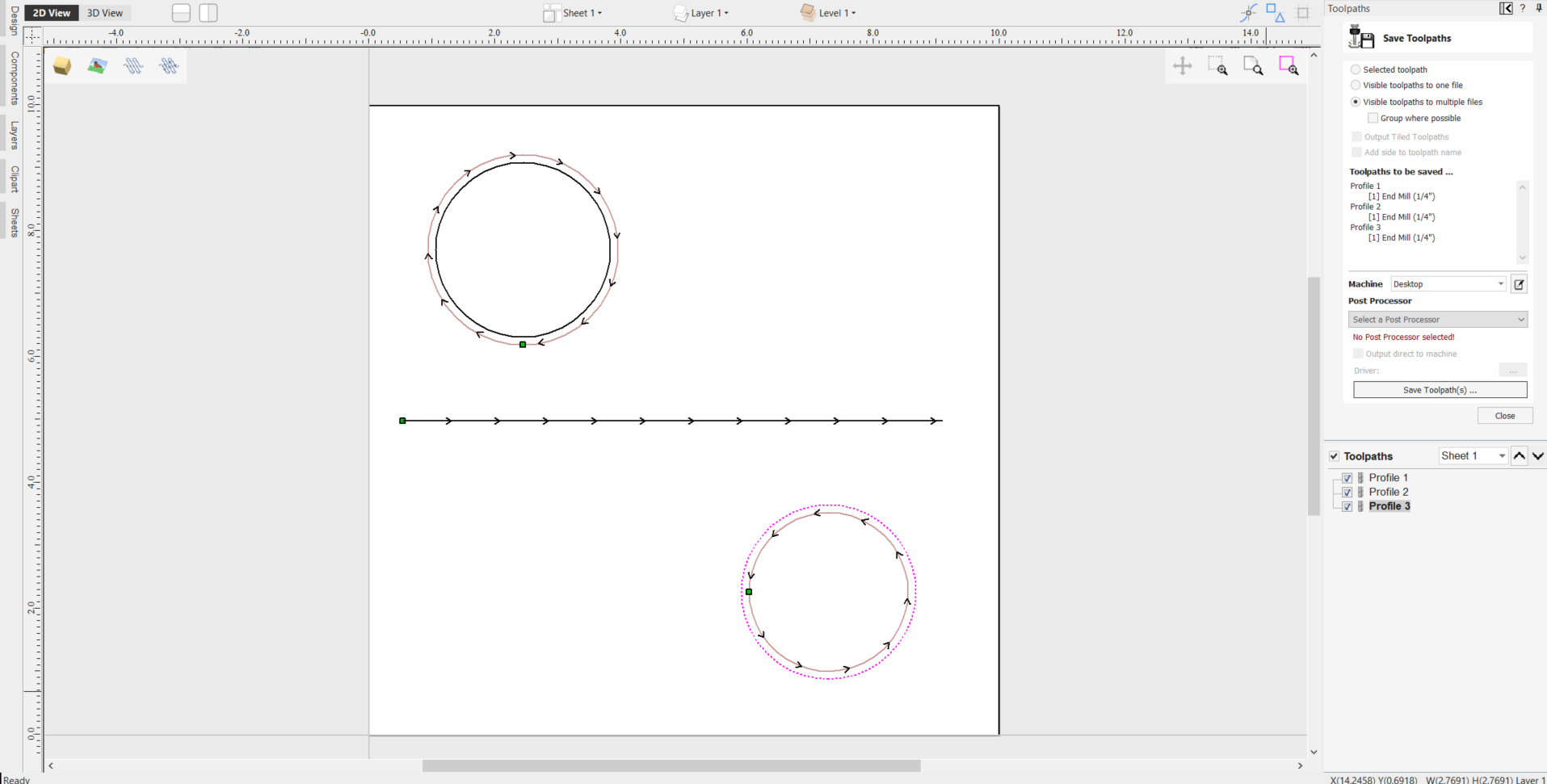
Save a toolpath using your base post processor and take a look at it using your favourite text editor. Below is an example of the test file posted using the "G-Code Arcs (inch) (*.tap)" post processor The example below is displayed using the popular Notepad ++ editor.
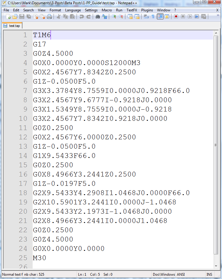
For our example, we will add a tool-change section to this post processor. Go to the Machine Configuration option under the machine menu.
In the Associated Post Processor section, click on the (+) icon and scroll down the list to locate your Post Processor in the list.
Right click on it and select Customise
A new copy of the Post Processor will appear at the top of the list with a pen icon next to it.
Right click on this copy and select Open File Location
This will open the Windows folder with the .pp Post Processor file itself which you can then directly edit if you need to adjust commands to fit your particular machine setup. These .pp Post Processor files can be edited in any standard Text Editor software
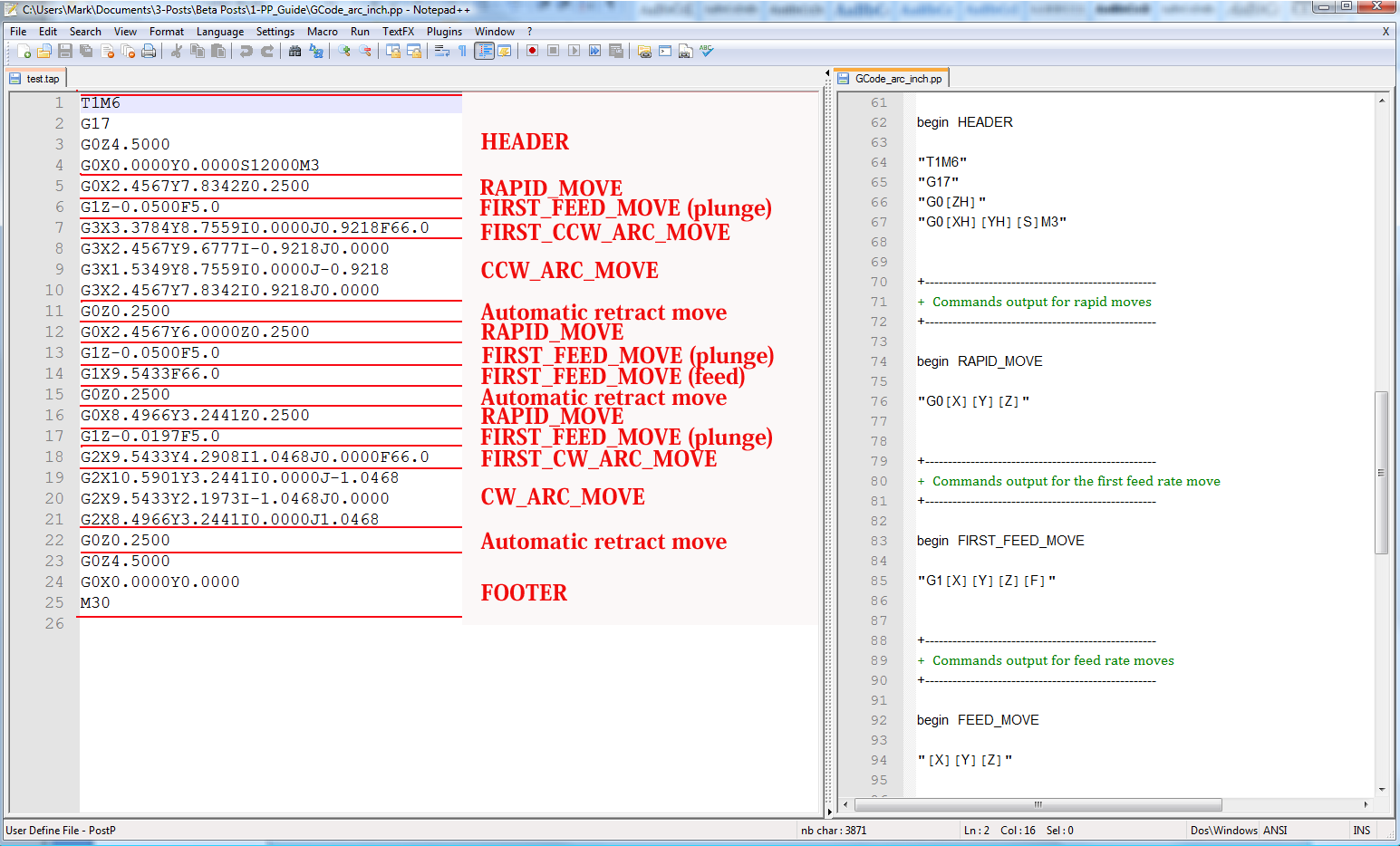
To add a Tool Change section to the post processor, you will need to consult the documentation for the control of the machine tool (or control software). For this example, we will assume that the instructions that you need to add to perform a tool change for your particular machine tool are as follows:
- M05 Instruction to turn off the spindle prior to tool change.
- M0 Instruction to return existing tool to tool holder.
- M06TTool_Number n Instruction to select new tool Tool_Number n
- G43HTool_Number n Instruction for control to use Tool length offset for tool n
- Sxxx M03 Set spindle speed to xxx; Turn on spindle (clockwise rotation).
Edit the post processor using your favourite text editor.
If the operating system on your computer is Microsoft Vista and User Access Control is enabled, copy or move the Post Processor that you are editing from the PostP folder to a folder below your user area.
The first thing that you should edit within the file is the History Comment section; So that you have a record of the changes.
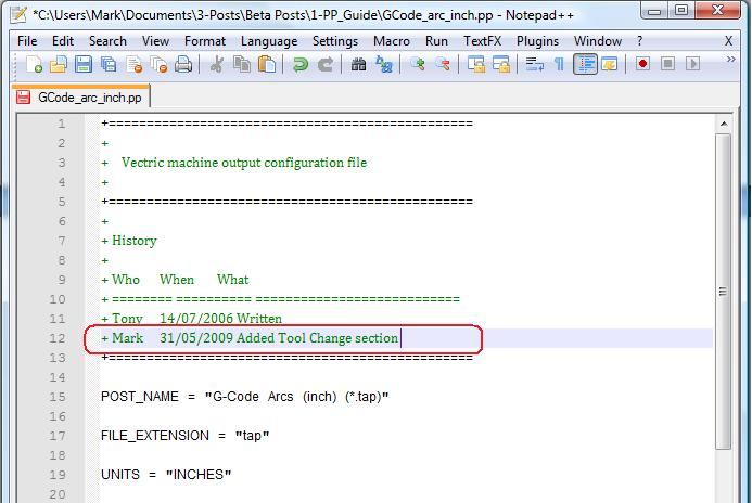
Next edit the POST_NAME to reflect that this post processor outputs automatic tool change (ATC) commands, the new post will be displayed as “G-Code ATC Arcs (inch)(*.tap)” in the list of post processors.
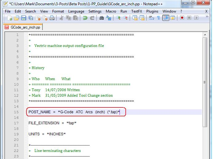
Next add a Tool Change Section that will include the instructions. The location of the new section within the file is not important, but a good place to insert it is between the Header and Rapid Move sections.
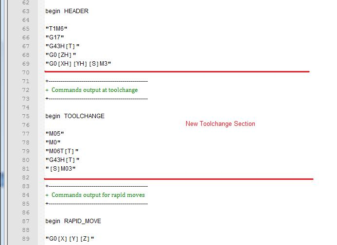
Add some comment lines at the top of the new section, (beginning with the + character) to describe the section and make the file as a whole, easier to read. Next enter the line “begin TOOLCHANGE” to instruct the post processor that the following instructions are to be output for every tool-change, (except the initial tool selection, the commands for these are contained within the header section).
The next step is to enter in the instructions that you require, enclosed within double quote marks. The “[T]” on the third and fourth instruction lines of our example, will be substituted with the tool number when the file is post processed; The “[S]” on the fifth line will be substituted with the spindle speed for the tool.
Finally you will need to save the changes to the file, as you have changed the POST_NAME, save the file using a new name, for example “GCODE_ATC_Arcs_inch.pp”
If the operating system on your computer is Microsoft Windows 7 or Microsoft Vista and User Access Control is enabled, copy the file that you have edited back to the “PostP” folder.
To test the new post processor, If the software is running, restart the software.
If there are any syntax errors with your post processor, an error similar to the picture below will be displayed as the software starts, the post processor that you have edited will not appear in the drop down list of post processor configuration files. You will need to rectify any errors and restart the software.
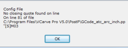
If there are no errors displayed when the software is started, open your test file and save one or more of your test toolpaths.
Select the post processor from the drop down list of post processor configuration and press the “Save Toolpath(s)” button.
Take a look at the file that you have just saved in a text editor.
If the content of the file looks good, try the file on your machine.
Please take all necessary precautions when running the output from a modified post processor for the first time.
Example: Changing the File Extension
The File extension that is automatically produced by the post processor can be changed within the “Save As” dialog box, when you click on the “Save Toolpath(s)” button.
However, rather than change the file extension every time. It is more convenient to permanently change the file extension produced by the post processor.
To do this:
For our example, we will add a tool-change section to this post processor. Go to the Machine Configuration option under the machine menu.
In the Associated Post Processor section, click on the (+) icon and scroll down the list to locate your Post Processor in the list.
Right click on it and select Customise
A new copy of the Post Processor will appear at the top of the list with a pen icon next to it.
Right click on this copy and select Open File Location
This will open the Windows folder with the .pp Post Processor file itself which you can then directly edit if you need to adjust commands to fit your particular machine setup. These .pp Post Processor files can be edited in any standard Text Editor software
Edit the post processor using your favourite text editor.
If the operating system on your computer is Microsoft Windows 7 or Microsoft Vista and User Access Control is enabled, copy or move the Post Processor that you are editing from the PostP folder to a folder below your user area.
Look for the following two lines within the post processor configuration file that begin with:
POST_NAME =
FILE_EXTENSION =
and alter these accordingly.
For example, if you wished to change the file extension produced by the “G Code ATC (inch)(*.tap)” post processor from “.tap” to “.nc”. Then edit the lines:
POST_NAME = "G Code ATC (inch) (*.tap)"
FILE_EXTENSION = "tap"
to make them read:
POST_NAME = "G Code ATC (inch) (*.nc)"
FILE_EXTENSION = "nc"
Save the changes to your file. If the operating system on your computer is Microsoft Windows 7 or Microsoft Vista and User Access Control is enabled, copy the file that you have edited back to the “PostP” folder.
To test the new post processor, If the software is running, restart the software. If there are any syntax errors with your post processor, an error similar to the picture below will be displayed as the software starts, the post processor that you have edited will not appear in the drop down list of post processor configuration files. You will need to rectify any errors and restart the software.
If there are no errors displayed when the software is started, open your test file and save one or more of your test toolpaths.
Select the post processor from the drop down list of post processor configuration and press the “Save Toolpath(s)” button.
Take a look at the file that you have just saved in a text editor.
If the content of the file looks good, try the file on your machine.
Please take all necessary precautions when running the output from a modified post processor for the first time.
Tips And Tricks
1. Always make a safe copy of the post processor that you are editing, in case you need to start again from scratch.
2. If using a word processor program, such as Microsoft Word, to edit a post processor, make sure that the file is saved as plain text. The file should not contain formatting information.
3. If editing post processors on a computer that runs Microsoft Windows 7 or Microsoft Vista, do not edit the files directly within the “Program Files\Product folder\PostP” folder. Always edit the file within your user area and copy the edited file to “Program Files\Product folder\PostP”.
4. Use comments when you make changes, a comment is a text that follows a + or a | character. Comments will not be acted upon by the program but can help in documenting changes that you have made and make those changes understandable in the future.
5. All Instruction lines must be contained within quote marks.
6. If possible, use a text editor that makes use of line numbers; This will make it easier to debug the post processor if there are any errors in the file. The program will check the post processors in the PostP folder when the program starts. If syntax errors are present in the file, an error message will be displayed, showing the line number of the first error encountered.
7. Once you have successfully edited a post processor, make a safe copy of it. If you install a later version of the Vectric product that you are using, remember to copy your modified post processor to the PostP folder of the new version of the software. And select your modified post processor, the first time that you save a toolpath, (The software will remember your selection for subsequent actions).
8. If you install another version of the software or you upgrade the version of the software, remember to copy your safe copies of your edited post processors to the PostP folder of the new version. Ensure that you select the correct post processor the first time that you post process a file using the new version of the software.
9. For later versions of the software, ( V5.5 and above). The post processors should be accessed from within the application, by clicking “File > Open Application Data Folder\PostP folder.
10. A customized list of post processors can be created by copying only the post processors required to the “File > Open Application Data Folder\My_PostP folder. If any file with a .pp file extension exists in the “My_PostP” folder, then only the post processors that exist in the My_PostP folder will be displayed in the drop down list of post processors.
Photo V-Carve Toolpath
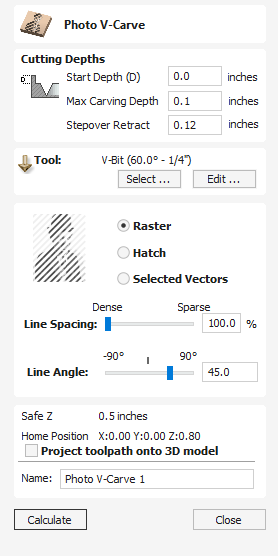
The Photo V-Carve toolpath uses the V-bit to etch a copy of the selected bitmap picture into the surface of your material.
Watch this video to see this in action:
Preparing the bitmap
This strategy requires a source bitmap image or photograph to be selected in the 2D View.
Your source bitmap can be edited in a number of ways before using this form to create your Photo V-Carve toolpath. You can use the Crop Bitmap command to trim a bitmap to a vector outline. This will allow you to remove any parts of a bitmap that you do not require.
The Edit Picture tool can also be used prior to creating the toolpath in order to adjust many important aspects of your image - such as brightness and contrast. In addition it can be used to add a feathered border the image. For the best results you should use this tool to highlight and accentuate out the important details of your image before creating your toolpath.
The fields on the form are as follows.
Cutting Depths
Start Depth (D)
This specifies the depth at which the Photo V-Carving toolpath is calculated, allowing Photo V-Carving to be machined inside a pocket region. When cutting directly into the surface of a job the Start Depth will usually be 0.0. If the Photo V-Carving is going to be machined into the bottom of a pocket or stepped region, the depth of the pocket / step must be entered. For example, to carve or engrave into the bottom of a 0.5 inch deep pocket, the Start Depth = 0.5 inches
Max Carving Depth
Max carving depth is the maximum depth the tool will cut into the material. It also impacts the number of lines that can be carved into a job at a specific size.
Stepover Retract
This parameter specifies how much the tool will retract before moving to the next line. This should be set to a value high enough, to allow tool to move safely to start of the adjacent line, but as low as possible to avoid slowing down machining.
Tool
Clicking the button opens the Tool Database from which the required VCarving or Engraving Tool can be selected. See the section on the Tool Database for more information on this.
Clicking the button opens the Edit Tool form which allows the cutting parameters for the selected tool to be modified, without changing the master information in the database.
Strategy Settings
Raster
Selecting this option will generate a single set of parallel lines, or stripes, across your selected image.
Hatch
This option will create two sets of parallel lines at 90 degrees from one another. This strategy will generally produce a denser image reproduction, but will typically take twice as long to etch.
Selected Vectors
Selecting this option will generate toolpath along the selected vectors. This is an advanced option that allows to produce special effects, but requires more time to set-up. You can use the Vector Texture tool to generate the vectors for use here.
Line Spacing
This slider adjusts the gap between the raster stripes - tight striping produces a denser image reproduction, but will take a lot longer to etch. The line spacing is expressed in percentage of the tool width at maximum carving depth .
At 100% the line spacing is calculated to create a 'knife edge' ridge in the deepest regions of the design - no flat left on the material surface. This is the maximum definition / resolution based on the specified Depth.
Increasing the Line Spacing, reduces the number of lines and increase the width of the flat regions on the material surface.
Line Angle
Adjust this slider to change the angle of the stripes or hatching used to etch the image. Zero degrees will produce horizontal stripes and ninety degrees, vertical.
Position and Selection Properties
Safe Z
The height above the job at which it is safe to move the cutter at rapid / max feed rate. This dimension can be changed by opening the Material Setup form.
Home Position
Position from and to that the tool will travel before and after machining. This dimension can be changed by opening the Material Setup form.
Project toolpath onto 3D Model
This option is only available if a 3D model has been defined. If this option is checked, ✓ after the toolpath has been calculated, it will be projected (or 'dropped') down in Z onto the surface of the 3D model. The depth of the original toolpath below the surface of the material will be used as the projected depth below the surface of the model.
Note:
When a toolpath is projected onto the 3D model, its depth is limited so that it does not exceed the bottom of the material.
Name
The name of the toolpath can be entered or the default name can be used.
Draw Line
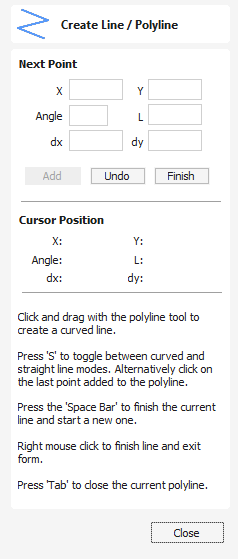
This tool creates continuous straight lines through points clicked, entered coordinates, tangent between a point and an arc or tangent to two arcs.
It can also be used to create smooth Curved lines.
Watch this video to see this in action:
Interactive - Cursor
The quickest and easiest way to draw a line is by clicking within the 2D View using the mouse.
- Click the left mouse button to indicate the start point of your line.
- Move the mouse pointer and click again to set the next point in your line.
- Repeat this process to add as many line segments as you require.
- Right-click or press Esc to finish your polyline and exit the form.
- Alternatively press the Space bar to complete this polyline but keep the form open and begin drawing another polyline.
- Press the Tab key to automatically close the vector.
- A smooth bezier span can be created by clicking and dragging to modify the curvature. The next span will then also be smoothed. If you want next line to be straight line then you can press S to disable the smoothing.
Curved Lines
- There are two separate curve modes in the polyline tool
- While in straight line/polyline mode, click in the 2D or 3D View to begin drawing a one-shot curve at the clicked point.
- Upon adding your initial point, move the mouse pointer within the 2D View to your desired end point and click and hold the mouse left button to being creating a curve by dragging the mouse to pull out the Curved Line. Release the Mouse button to place your curve.
- A curve will be created that smoothly joins your points.
- You can switch between creating Lines or Curves, using Left Click and release for Lines, and Left Click, Drag and then release for Curves.
- You can also press 'S' on the keyboard to toggle between curved and straight line modes. Alternatively, while in curved drawing mode if you click on the last point added to drawn line, this will exit draw curves mode and will return to draw polyline mode and vice versa, if you are in draw polyline mode you can click on the last point created to return to draw curve mode.
- Ensure snapping options are enabled within the software so the last created point can be snapped to.
- The software will retain the last instance of the curve or line mode used. So if a user closes the software, upon the next use of the Draw Polyline tool, the last mode used - curve or straight - will be enabled.
Left Clicking
Left clicking when the mouse pointer is close to the first point on the curve will snap the curve closed.
Extend Existing open Vector path
In order to extend an existing open vector using the Create Line Drawing tool;
- Hover your cursor over the point you wish to join from
- Holding down Ctrl > Left Mouse Button within the immediate area of this point > Drag to draw path
- Release Left Mouse Button to complete path.
Creating Tangent Lines
The polyline tool can also be used create lines that are tangent to arcs in your existing drawing.
From A Point To An Arc
To create a line tangent from a point to an arc simply enter the initial point and then hover the cursor over the arc and press T.
From An Arc To A Point
To create a line tangent from an arc to a point click on the arc to insert a point and then hover the cursor over the next point position and press T
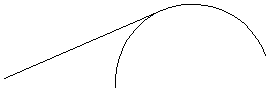
Note
You cannot create a tangent line to a bezier curve
From An Arc To Another Arc
To create a line tangent from one arc to another click on the arc to insert a point and then hover the cursor over the second arc and press T.
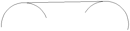
Note
Arcs are not trimmed as a result of creating a tangent line
Quick Keys
Instead of releasing the left mouse button when you have dragged your shape to the required size, you can also type exact values during the dragging process and set properties precisely.
- Left-click and drag out your shape in the 2D View.
- With the left mouse button still pressed, enter a quick key sequence detailed below.
- Release the left mouse button.
By default, entering a single value will be used to add a point at the specified distance along the line direction currently indicated by the mouse pointer position, relative to the preceding point. With polyline drawing underway, move the mouse pointer in the direction you wish to create a new line segment and type Length Value Enter to extend the line by the specified distance in that direction.
By default two values, separated by a comma, will create the next line point at the absolute X Y coordinate indicated by the two values, respectively. While drawing, type X Value, Y Value Enter to place the next point precisely at specified X and Y position
Examples
- 3 . 5 Enter - Adds the next point at a distance of 3.5 along the line direction indicated by current mouse direction
- 1 , 2 . 5 Enter - Adds the next point at the absolute position 1 in X and 2.5 in Y
Specifying Further Properties
By using specific letter keys after your values, you can also specify the line segment in terms of angle and length. Using the key sequence value A value L creates the next line segment at angle (A) degrees from the last point and with a length(L)
Examples
- 45 A 3 L - Creates a line segment at 45 degrees and length 3
Next Point
You can also use the form to enter values for each line segment as you go along. The segments can be defined using :
- The absolute X Y position of the next point
- The Angle and Length to the next point
The relative offset in X (dx) and Y (dy) to the next point.
Once you have entered the values you wish to use :
- Click the Add button to enter a new point.
- The Undo button deletes the last point entered and allows a new point to be added. The Backspace shortcut can also be used for this.
- The Finish button completes drawing the current line and leaves the form open to allow additional lines to be drawn.
Note
The X Y position use absolute coordinates. The Angle, Length and dx/dy positions are incremental from the current position.
Usable In Both Views
This tool can be used in both the 2D and 3D View.
2D View offers a more direct way to view your vectors while 3D Offers more flexability to work with Vectors in 3D Designs and to make use of the Edit Boxes.
Component Properties
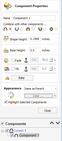
The Component Properties form allows you to adjust a number of dynamic properties for a selected Component or Level. Adjusting these properties does not make permanent changes to your Components and can be further edited or reset any time until the component is Baked, in which cases they will be made permanent in the Component shape and this form will be reset.
Note
You can only edit the Name, Combine Mode, Base Height and Appearance for the Properties of a Level.
Double Click the Components Name in the Component Tab to open the Component Properties.
Multiple Selections
If you have more than one component selected while using the Component Properties tool, Aspire will apply the changes to all the selected components. Some properties where this would be inappropriate (such as the component's name) are grayed-out when there is more than one component selected. These properties must be applied to components one at a time.
Combine with other components
The Combine Mode dictates how the components (or Level) are combined with the objects below them in the Component Tree. This is done by the software starting at the bottom of the list and working upwards. The first level and first component's combine mode determines only how it combines with the modeling plane. The second and subsequent components are combined with the result of everything below them based on their Combine Mode as detailed below. See Component Tree for more details.
Add

Adds the selected component/s to the result of all the previous components in the list.
Subtract

Subtracts the selected component/s from the result of all the previous components in the list.
Merge

Where they overlap, this Merges the selected component/s into the result of all the previous Components in the list keeping the highest part of the overlapping area. This means the higher part of each shape will be what remains in this area.
Low

Where they overlap, this Merges the selected component/s into the result of all the previous Components in the list keeping the lowest part of the overlapping area. This means the lower part of each shape will be what remains in this area.
Multiply

Where there is an overlap, this Multiplies the result of all the previous components in the list by the heights in this component.
Shape Height
Use the slider or type in a specific percentage to scale the height of the selected Component(s) up or down based on its current height (100%).
Enter a value in the Shape Height edit box directly, or use the slider to adjust the height of your component selection interactively. In either case, the 3D view of the component will update automatically as you adjust the value. The range of available heights on the slider is determined by your current material thickness setting. If these values appear to be inappropriate you can still enter any value you like into the associated edit box, or you can close the tool and select Edit ► Job Size and Position from the main menu. In the Job Setup page you can then correct the current setting for the material thickness before continuing.
Base Height
Enter a specific value into this box to raise the Component or Level up on a flat plane of the thickness you specify. This can be useful to help move an object up so it sits proud of another component it is Merging with. If you are not sure of the value you need, then enter an amount and hit the space bar to apply this. If this is not correct, type in another value and hit space again to apply the new value, look at the 3D View to judge the result - repeat until you get the value you need.
You can also apply a Base Height to a Level. Adding a base height to a level will add the same base height visually to the components in that Level, however the components themselves will have no base height added to them within their properties. This is useful to raise a set of objects on a Level above things that need to appear to be behind them (for example above a textured area).
Note
Level Base Heights are not included in Baking operations on the Components on those Levels but are a separate value that is added on after the objects on the Level have been combined. They are scaled proportionately though when the Scale z height of Model function is used to adjust the Z Height of the Composite Model (visible components).
Reset Heights
The button will remove the dynamically applied Shape and Base height settings from the selected component. To reset the Base Height back to zero using the slider control, double click the central line marker above the slider bar.
Fade
When this option is checked ✓ the user can fade the Z depth of the Component. The first part of this operation (once the option is checked ✓) is to select the button - then click two points in the 2D view. The first click specifies the point which will remain at the current height. The second click specifies the point that the Component will be faded down toward. The shape will fade down from the first point to the second by the percentage selected. Change the strength of the fade by clicking the down arrow next to the percentage value and using the slider to move this up and down or type in a specific value for the amount you would like to reduce the depth by. The fade will be applied linearly between the two selected points. This is a useful tool for giving the effect of a Component fading into the distance to help with overlapping areas of Components if you want to lower an area to give it the appearance of going behind another one.
Tilt
When this option is checked, ✓ the user can set a direction and angle to tilt the Component up in the Z axis. The first part of this operation (once the option is checked ✓) is to select the button - then click two points in the 2D view. The first click specifies the point which will not move (the pivot point of the tilt). The second click specifies the point that will be tilted upwards by the specified angle (the point that will be raised up). Change the tilt angle by clicking the down arrow next to the value, you can use the slider to alter this, or type in a specific value for the angle. This is an extremely useful function for raising a part of one Component above another one when they overlap, without having to raise the whole Component up using the Base Z Position option. In some cases this allows the overlapping areas to sit proud without having to create a deep raised wall around the whole edge of the Component.
Bake
Sometimes it's useful to apply a component's dynamic properties permanently, one example where this is useful is so that further dynamic changes can be applied 'on top' of previous ones. To do this, use the button.
Appearance
Aspire gives you a lot of control over the appearance of the 3D shaded image for visualization purposes, such as customer approval proofs or marketing material. Each component can be given an individual color or material.
Same as Parent
Use appearance of the objects parent. This is a level for components and the model in case of level. This will ultimately use the model's appearance, as specified in Job Setup.
Solid Color
This option allows to use a single color for shading the component.
Use Material
When this is selected the user can choose from the list of pre-defined material effects by clicking on the box immediately below the Appearance choice. These include many wood grains, metal effects, stone and plastic.
Additional materials can be added to the library. See Preview Toolpaths for more details.
Color from Children
This option is used for a Group of Components or Level and will allow the software to use the individual colors and materials assigned to the groups constituent Components to display in the shaded image even though it is a Group. If this option is not selected the Group/Level will be given its selected Color or Material.
Highlight Selected Component
When choosing a material or color to use for a particular component, the red selection highlighting of the component can prevent you from seeing your chosen material accurately in the 3D view. You can un-check this box to temporarily disable the red highlighting while you make your selections. This option will automatically be re-enabled on exiting the Component Properties page.
Close
The button will exit the Component Properties form and return to the standard set of modeling icons.
Node Editing Mode
The Node Editing tool can be selected from the Editing window or by pressing the Keyboard shortcut N to toggle between Selection and Node Editing modes.
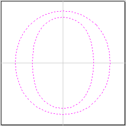
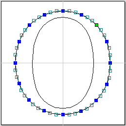
Watch this video to see this in action:
When the Node Editing tool is active the cursor changes to a Black Arrow indicating that individual points (nodes) and their connecting spans can be edited. Nodes can be interactively moved by clicking and dragging the left mouse button on a node to select and move the node to a new position.
The shape of lines, arcs and Bezier (curve) spans can be edited by clicking and dragging on the nodes or control points to move them. Multiple nodes and control points can be selected and moved by using the multiple selection options such as the Shift key and dragging to make a selection.
The shape of individual spans can also be edited by dragging the span itself using the left mouse button.
Holding down the Ctrl key while dragging an arc or Bezier span will move the entire span rather than change its shape.
The start and end directions of Bezier curves can be fixed when being dragged directly, by toggling on Keep Bezier Tangency mode.
If you right click on nodes or spans a context sensitive popup menu will be displayed which allows you to insert or delete points and nodes, cut the vector, move the start point, etc.
Node editing vectors is a very powerful way to be able to make changes to the vectors in your part.
Useful Tip
Smart Snapping combined with Distance Snapping or Quick Keys can give more accuracy when dragging nodes.
Usable In Both Views
This tool can be used in both the 2D and 3D View.
2D View offers a more direct way to view your vectors while 3D Offers more flexability to work with Vectors in 3D Designs and to make use of the Edit Boxes.
Weld Vectors
Selected closed vectors that overlap can be merged together to create a new shape. These tools consider the closed vectors to be solid areas.
The following examples begin with these five vector shapes where the rectangle was selected last.
Welds overlapping vectors together to create a new shape which follows the outermost edge of all the selected shapes.
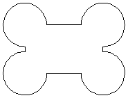
When welding text, the internal regions of characters are preserved.
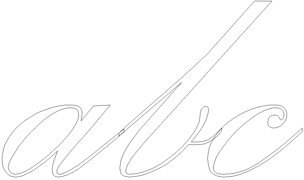

Watch this video to see this in action:
Usable In Both Views
This tool can be used in both the 2D and 3D View.
2D View offers a more direct way to view your vectors while 3D Offers more flexability to work with Vectors in 3D Designs and to make use of the Edit Boxes.
Inlay Toolpath
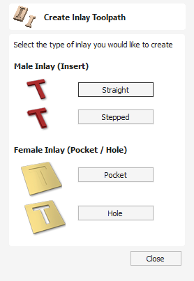
The Inlay toolpath functionality can be used to calculate either profile or pocketing toolpaths with automatic compensation for the tool radius; this allows the cut-out parts to fit into the corresponding cavities. This is a great feature for creating decorative woodwork and is also particularly useful for sign makers for creating inlayed letters and graphics.
Watch this video to see this in action:
How Inlays Work
When using a CNC machine to cut out shapes then the tool will always leave a radius on any internal corner. When cutting holes or pockets the tool conversely leaves a radius on the external corners. If no changes are made to accommodate this then there would be no way to fit one part into the other. This is shown highlighted on the letter 'T' shown in the image below. On the left you can see the internal corners with a radius on the part being cut out (highlighted with red ovals). On the right you can see the radiused external corners on the hole (highlighted with green ovals). As you can envisage trying to slot the 'T' into the hole would not work as it is the proverbial square peg in a round hole!
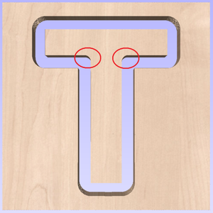
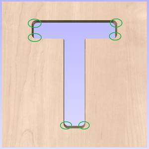
It is not possible to avoid the added radius as it is formed by the tool size and shape. The Inlay function though, will create toolpaths which take the tool radius into account and compensate for it by rounding off the sharp corners so the resulting parts will fit together. This can be seen in the images shown below where the same letter has been cut using the Inlay toolpaths, you can see all corners (internal and external) now have the same radius so they will slot together
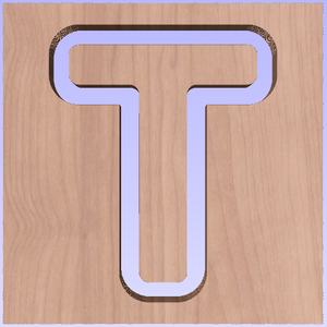
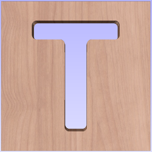
When creating an Inlay toolpath the radius is automatically compensated for, so it is very important to make sure you specify the same tool for both parts of any inlay (male and female). If you do not do this the Inlay will not fit together.
If creating a Pocket then the main Tool (the finish tool) not the larger (clearance) tool should be the same as the one as used for creating the Male Inlay.
Note
You must use the same tool for both parts of an inlay for the resulting parts to fit together correctly.
Male Inlay (Insert)
Straight
This option is for cutting out straight sided parts to act as the inserted piece of the inlay. It uses a variation on the Profile toolpath which will automatically round the external corners of the part to allow for the radius of the tool being used. All the standard Profile options are available in this form except there is no option to Profile Inside or On as this does not apply to this inlay type as it has to cut outside of the vector. The other standard options not available are the ability to add sharp Corners or set a Last Pass as again these would not apply to this application. The image below shows how the external corners are rounded based on the tool radius being used.
Stepped
This option is for cutting out stepped sided parts to act as the inserted piece of the inlay. This style of inlay is typically used for what are referred to as 'Push Through' letters and shapes. These are parts which are inserted from the back and use the step as a shelf to invisibly mount them to the back of a sign. As with the Straight Inlay option it uses a variation on the Profile toolpath with the addition of the ability to specify a Step Depth and Step Width.
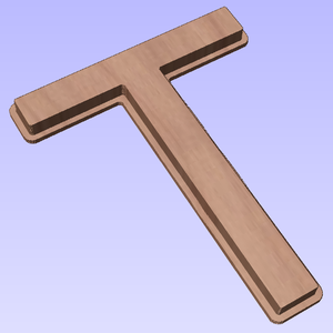
As the diagram shows in the form, the Step Depth is the vertical height of the step from the Start Depth down, the Step Width is how far from the edge of the original vector the part will be cut out (creating the step).
Female Inlay (Pocket / Hole)
Pocket
This option is selected for cutting out a Pocket to act as the cavity for the corresponding Male shape to inlay into. It uses the same options as the standard Pocket style toolpath including the new option where you can use a larger and smaller tool to clear the pocket (smaller tool size should match that used for the Male Inlay). In order to make it work as an inlay pocket any internal corners will be rounded based on the tool radius to allow the male parts to fit into them (shown in the image below).
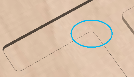
As has been previously discussed it is common to leave an allowance on one or both sides of the inlay, typically when working with letters the allowance would be left on the Pocket so the size and shape of the lettering itself is not affected any more than necessary.
Hole
This option is for cutting out a Hole to act as the cavity for the corresponding Male shape to inlay through. The standard Profile options are available for Female Hole Inlays except there is no option to Profile Outside or On as this does not apply to this toolpath type and this option does not allow the use of the Corner options as these are also inapplicable to this type of toolpath. In order to make it work as an inlay, any internal corners will be rounded based on the tool radius to allow the male parts to fit into them (shown in the image below).
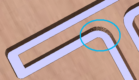
Setting Inlay Allowances
Although the radius of the tool is compensated for when using the inlay tool, this in itself will almost always not be enough to ensure the two parts will fit together correctly. The parts will be exactly the same size and so would not fit together without a lot of force which would damage the part or without some kind of post-CNC hand work. Cutting the parts exactly the same size also does not allow for any kind of finish to be applied to either side.
To enable the parts to fit extra material either needs to be cut from the Male side, the Female side or in some applications both. This additional distance is added using the option in the toolpath form to add an Allowance. On the toolpaths which are based on a Profile then this is done with the Allowance Offset (Shown in the image below left - highlighted in red). For Pocket style toolpaths use the Pocket Allowance, (shown in the image below right highlighted in red). When a value is entered it will overcut the selected shape by this distance, this will reduce the size for male parts and increase the hole/pocket for female parts.
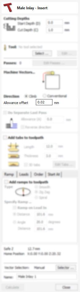
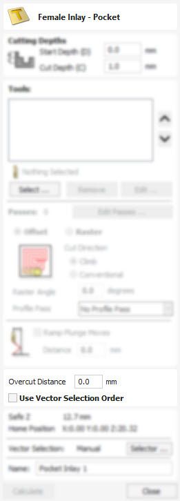
The size of the Allowance required will depend on the type of material (how much it may expand or contract between being cut and inlayed), the accuracy of your tooling, the accuracy of your machine and finally any finish you are planning to add to the finished parts (such as paint or varnish which will have a thickness). In most situations where no finish is being applied before the parts are inlayed then an allowance of 0.01 inches (0.25mm) or 0.02 inches (0.5mm) will be sufficient. If you are not sure what value to use then you should experiment with this on a test part to get the correct sizes for your particular setup and application.
In the majority of cases the Allowance is applied to the Female side of the inlay as it is typical to not want to alter the actual vector shapes (the Male side) any more than is required for the tool radius. This means the Hole or Pocket will be cut over-sized to provide the additional allowance for the parts to fit.
Position and Selection Properties
Safe Z
The height above the job at which it is safe to move the cutter at rapid / max feed rate. This dimension can be changed by opening the Material Setup form.
Home Position
Position from and to that the tool will travel before and after machining. This dimension can be changed by opening the Material Setup form.
Project toolpath onto 3D Model
This option is only available if a 3D model has been defined. If this option is checked, ✓ after the toolpath has been calculated, it will be projected (or 'dropped') down in Z onto the surface of the 3D model. The depth of the original toolpath below the surface of the material will be used as the projected depth below the surface of the model.
Note:
When a toolpath is projected onto the 3D model, its depth is limited so that it does not exceed the bottom of the material.
Vector Selection
This area of the toolpath page allows you to automatically select vectors to machine using the vector's properties or position. It is also the method by which you can create Toolpath Templates to re-use your toolpath settings on similar projects in the future. For more information, see the sections Vector Selector and Advanced Toolpath Templates.
Name
The name of the toolpath can be entered or the default name can be used.
02. Getting Started - Introduction
Getting Started
Welcome to the vibrant Vectric community! You've made a great choice for getting the most from your CNC machine by using Vectric software. This short guide should help you to get your CNC machine cutting correctly in less than hour. Along the way we will highlight key concepts and tools in our full Reference Manual. These links will help you review each step in more detail and begin to develop your skills.
Overview
In the first section of this guide we will describe the main principles of CNC toolpath creation using Vectric software. All CNC projects follow a similar workflow and our software is designed to reflect these steps naturally and intuitively.
Next we will complete your one-time setup to licence your product and give you access to Vectric's online portal, V&Co, which we will use to automatically configure the software for your specific CNC machine.
In the final section we will run through a simple, but complete, CNC project from start to finish step-by-step. At the end of the project you should be confident that your CNC machine is correctly configured and you can cut vector drawings using a simple profile toolpath strategy.
3D Rough Toolpath
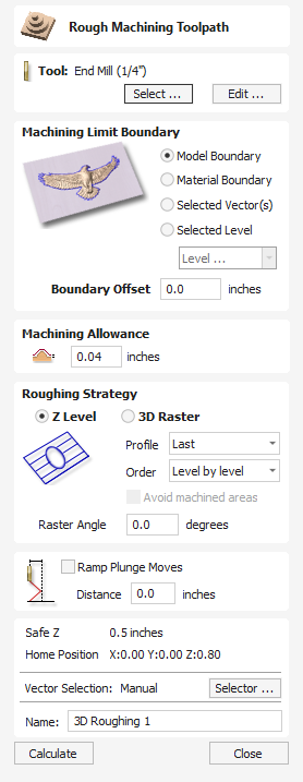
Rough Machining is used when carving 3D parts to clear away excess material when the part is too deep for the finishing tool to cut in a single pass.
Clicking on this icon opens the toolpath form shown to the right; the functions available within this are described below.
Tool
Clicking the button opens the Tool Database from which the required tool can be selected. See the section on the Tool Database for more information on this. Clicking the button opens the Edit Tool form which allows the cutting parameters for the selected tool to be modified, without changing the master information in the database. Hovering the mouse cursor over the tool name will display a tool tip indicating where in the Tool Database the tool was selected from.
Machining Limit Boundary
The machining limit boundary is the area in which the tool will operate. There are several options:
Model Boundary The combined boundaries of all the components in this job are used. This is the area of the composite model which has components on it. Note: this is not the boundary of the selected models.
Material Boundary The boundary of the entire material block is used.
Selected Vector(s) Selected vectors are used as the machining boundary.
Selected Level The combined boundaries of all the components on the specified level. This is similar to Model Boundary, but only specific to the named level.
Boundary Offset
If you are machining a raised object, often the tool will not fully machine down the edge. This field is used to specify an offset to the selected machining boundary to increase its size to allow the tool to go past the actual edge if needed.
Note
The tool tip (rather than the cutting side) will not leave the machining boundary. This is to help ensure that roughing removes enough material on machining boundaries.
Machining Allowance
The machining allowance is a virtual thickness which is added to the 3D model when the Roughing Toolpath is calculated. This ensures that the toolpath leaves some extra material on the roughed part.
This is beneficial for two main reasons, the first is that when roughing it tends to be done with relatively large tool and aggressive cuts and so is more prone (depending on the material) to chip, this skin helps to prevent the chipping affect the finished surface. The second reason is that most tools cut well when they are constantly removing material. Therefore leaving an allowance of material on ensures that there is always at least some material for the finishing toolpath to remove.
Roughing Strategy
The roughing strategy determines the process the toolpath will take to remove the desired material
Z Level Strategy
Z Level Roughing essentially uses a series of 2D Pocket toolpaths which take into account the 3D model and hog-out the material around it within the specified boundary.
The first setting is the choice of Profile, this controls whether each level has a profile cut around its boundary or not and if so whether it cuts before the raster or after it. First does the profile before the Raster on each level, Last does the profile cut after the raster and None eliminates the Profile cut leaving only the raster pattern. These choices depend a lot on the material and tooling being used. For example, more brittle material may benefit from the profile first option to reduce chipping.
The second setting is the choice of Order. The Z Level can be performed in Level by level manner. This means to generate a complete pass at a given depth over the whole model, before advancing to the next level. This is the default option.
The user can also select Depth-first. In this case if at a given depth the model consists of separate regions, the generated toolpath will generate all passes at increasing depths over such region. Then it will advance to another such region.
3D Raster Strategy
The 3D Raster strategy is a 3D cut which passes over the whole model. This will leave a more even amount of material for the finish cut to remove but depending on the depth and style of the part it may take significantly longer to run. In shallower parts where the roughing is only taking one or two passes then this may be a better choice. For deeper parts then typically the Z Level rouging is a more efficient.
Raster direction
This option allows to define the main cutting direction.
Reverse step direction
By default, when using raster direction Along X the tool will move from one raster line to another from bottom to top. In case of raster direction Along Y the tool will move from right to left. This option allows to reverse that stepover direction.
Note
This option is currently only available for Z Level strategy.
Avoid Machined Areas
This option means that if an area has been machined by a previous pass of the toolpath it will not be machined by any later passes. This can mean the toolpath is quicker to machine
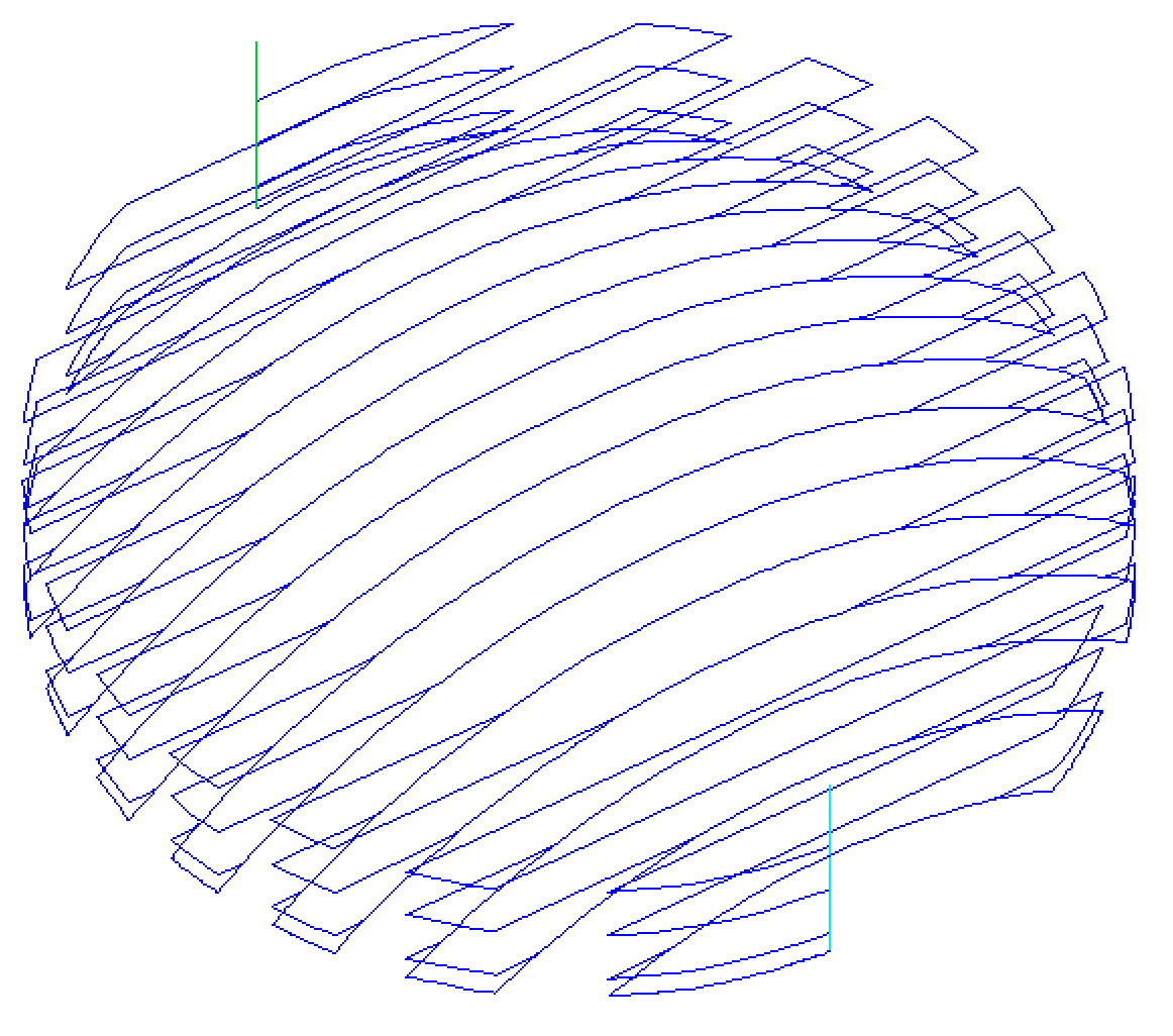
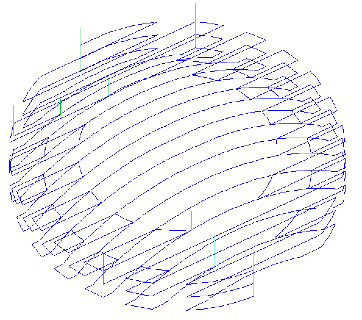
Note
It is not guaranteed that the toolpath is quicker. It might seem that skipping any previously machined areas should be quicker, but if this introduces more retracts and slows the machine due to extra acceleration and decelerations, then the final result could be slower.
Ramp Plunge Moves
The cutter can be ramped over a distance into the pocket instead of plunging vertically. This approach reduces heat build-up that damages the cutter and also reduces the load on the spindle and z axis bearings
Position and Selection Properties
Safe Z
The height above the job at which it is safe to move the cutter at rapid / max feed rate. This dimension can be changed by opening the Material Setup form.
Home Position
Position from and to that the tool will travel before and after machining. This dimension can be changed by opening the Material Setup form.
Vector Selection
This area of the toolpath page allows you to automatically select vectors to machine using the vector's properties or position. It is also the method by which you can create Toolpath Templates to re-use your toolpath settings on similar projects in the future. For more information, see the sections Vector Selector and Advanced Toolpath Templates.
Name
The name of the toolpath can be entered or the default name can be used.
Text On A Curve
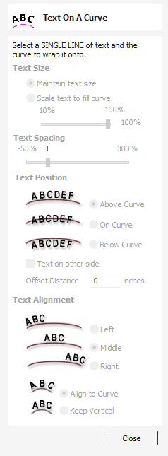
This tool requires the user to select a single line of text with the Draw Text tool and a single vector curve/line. It will take the text and fit it onto the selected vector to follow the curvature. Options within the tool allow position, space and location against the line to be edited.
To edit properties of text object that was already on a curve, just select the text object. To place it on another curve select both the text object and a vector.
It is also possible to use a closed vector to wrap the text around it.
Watch this video to see this in action:
Text Size
Maintain text Size
Will not change the size of the text block

Scale text to fill curve
Will increase the character size in order to fit along the entire length of the selected curve.
Text Spacing
The slider can be used to increase or decrease the word and character spacing. Each time the form is opened, or new text is selected, this control starts at the 100% mark. While this text is being edited the spacing scale can be increased or decreased from its original value.
Text Position
Above Curve
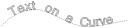
On Curve
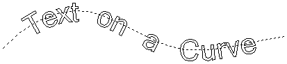
Below Curve
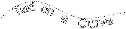
Text on other side
Offset Distance
Allows the text to be moved away from the curve by a specified distance.
Text Alignment
The 3 options allow the text fitted to the curve to be aligned to the left, middle or right hand side of the selected curve. Or, when using a closed vector curve, relative to the Start Node.
Note
Remember the Start node can be changed using the Node Editing Tools available from the Right mouse menu and selecting Reverse Direction.
Characters in the text string can also be aligned 'normal' to the drive curve or left in the original vertical position.
Position on the curve
The text's position on the curve can be adjusted interactively, by dragging the anchor point handle in 2D View.
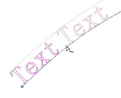
Detaching from the curve
The text object that was wrapped on a curve can be detached from it.
To detach text right-click on the selected text object and select "Remove Text From The Curve" option.
Usable In Both Views
This tool can be used in both the 2D and 3D View.
2D View offers a more direct way to view your vectors while 3D Offers more flexability to work with Vectors in 3D Designs and to make use of the Edit Boxes.
Vector Validator
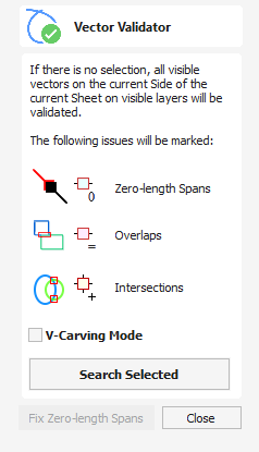
The Vector Validator is intended to help find issues with contours after file imports that are stopping tool-path creation such as overlapping contours or intersections. It also indicates zero-length spans.
The Vector Validator dialog can be opened with a selection to work on. If there is no selection, all visible vectors on the current Side of the current Sheet on visible layers will be validated. The selection can be changed while the form is open.
The text on the button changes to show whether all vectors or just the selection are going to be searched. While searching, the Search button becomes a Stop button.
To cancel a search, click the or button.
Issues found so far will be marked.
Watch this video to see this in action:
Marks
Examples of the marks described on the form are shown below:
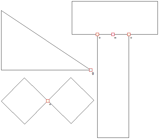
If zero-length spans are found, the button is enabled. Clicking this will remove the zero-length spans and clear their markers
V-Carving Mode
When this option is checked, Vector Validator will perform its vector checks as it is executed and required for V-cutting.
For example,
- It will ignore intersections that may exist within the text, as this may be due to problems in the font. If you get intersections that involve text, you could try soldering it and run Vector Validator on the output.
Toolpaths
 | Show Toolpaths Tab | Can be checked ✓ on or off to pin the Toolpath Tab open or unpin and hide it. |
 | Recalculate all toolpaths in the project. | |
| Toolpath Drawing ► | Opens the Toolpath Drawing submenu. |
| Preview Simulation Quality ► | This controls the resolution (number of points) in the Toolpath Preview simulation model governing the amount of detail that the model will display when you Preview and toolpath. The higher the quality, the slower the speed of simulation will become. Guidelines are given on how much slower you should expect it to be but these will depend upon the performance of the PC and relative size of the tool being used to your job (the larger the tool, the slower the performance).
|
| Templates ► | Opens the Toolpath Templates submenu |
 | Opens the Create Merged Toolpath Form to merge different toolpaths that use the same tool into one optimised toolpath. | |
 | Creates a job setup sheet which gives an overview of all of the toolpaths in the job. This opens a File Save As dialog prompting for a place to save the created sheet. The created job setup sheet is a single page of HTML, suitable for viewing in a web browser of your choice, or for printing. This can also be customized with the Job Setup Sheet Editor in the Gadgets Menu. | |
| Opens the Material Management dialog of the Tool Database | |
 | Opens the Tool Database Dialog. |
Toolpath Drawing sub-menu
| Draw 2D Previews | Can be checked ✓ on or off to display the toolpath previews in the 2D View. |
| Make 2D Previews Solid | Can be checked ✓ on or off to switch from the wireframe view to a solid view. |
| Auto Open 3D View | Selects whether the 3D view and Preview Toolpaths Form are automatically shown after toolpaths are created. |
| Draw rapid moves | Toggles the visibility of red rapid-speed move lines on the 3D view when toolpaths are visible. |
| Draw plunge moves | Toggles the visibility of cyan plunge-speed move lines on the 3D view when toolpaths are visible. |
| Draw retract moves | Toggles the visibility of green retract-speed move lines on the 3D view when toolpaths are visible. |
| Draw join moves | Toggles the visibility of purple join move lines on the 3D view when toolpaths are visible. A join move is a purely 2D move between toolpath contours, these are typically seen in Offset pattern Pocket Toolpaths. |
Templates sub-menu
Saves the toolpath that is currently selected as a template for use in another project. | |
Saves all of the currently visible toolpaths as a single template for re-use in another project. | |
Loads a previously stored template containing all the settings for one or more toolpath strategies. |
Prism Carving Toolpath
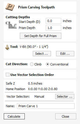
Prism carving gives a raised 'bevel' effect to shapes and letters similar to a 'hand carved' look.
Prism Carving uses an angled tool to create a raised prism shape on the top of the selected vectors. The tool will profile at a given depth creating a nice sharp finished shape such as the lettering shown in the image below. This is often paired with a Profile or Pocket toolpath to carve the vertical edge around the shapes or clear out the material between them. This type of toolpath is often, though not exclusively, used on lettering.
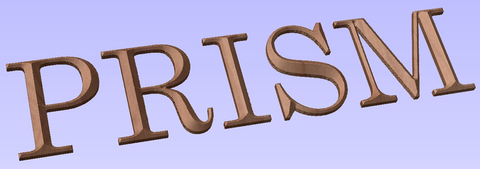
Watch this video to see this in action:
Cutting Depths
Start Depth (D)
Start Depth (D) specifies the depth at which the Prism Carving toolpath is calculated from. When cutting directly into the surface of a job the Start Depth will often be Z0. If machining into the bottom of an existing pocket or stepped region, the depth of the pocket/step that you are starting from must be entered here.
Prism Depth
This sets the depth of the Prism Carving toolpath relative to the Start Depth, the total depth of the base of the prism shape (within the material) will be the combination of the Start and Flute Depth. This depth is particularly important to set correctly as if it is too shallow then the prism shape may be truncated so it will have a flat top (shown in the image below right). The minimum depth needed to avoid this is determined by the widest point on the vector/s selected (W) and the angle of the tool (A). This can be calculated automatically by using the Set Depth for Full Prism function (see below for more details).
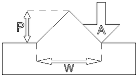
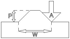
Set Depth for Full Prism
For this button to work you both need to select the vectors you plan to toolpath and also have selected the tool you are going to use, then when you click it, the Prism Depth will be set to the minimum required to ensure a full point on the prism for the current selection/tool.
Tool
Clicking the button opens the Tool Database from which the required tool can be selected. See the section on the Tool Database for more information on this. Clicking the button opens the Edit Tool form which allows the cutting parameters for the selected tool to be modified, without changing the master information in the database. Hovering the mouse cursor over the tool name will display a tool tip indicating where in the Tool Database the tool was selected from.
Cut Direction
The direction of cut can be set to either Conventional or Climb machining, the choice for this will largely be dictated by the material being machined and the type of tool being used. See the section on Profile Toolpaths in the Reference Manual for more information on the differences between these.
Position and Selection Properties
Safe Z
The height above the job at which it is safe to move the cutter at rapid / max feed rate. This dimension can be changed by opening the Material Setup form.
Home Position
Position from and to that the tool will travel before and after machining. This dimension can be changed by opening the Material Setup form.
Vector Selection
This area of the toolpath page allows you to automatically select vectors to machine using the vector's properties or position. It is also the method by which you can create Toolpath Templates to re-use your toolpath settings on similar projects in the future. For more information, see the sections Vector Selector and Advanced Toolpath Templates.
Name
The name of the toolpath can be entered or the default name can be used.
Celtic Weave Creator
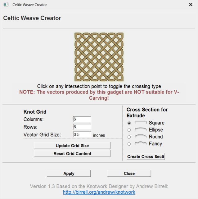
This Gadget dramatically simplifies the creation of complex 3D Celtic weave patterns using an interactive interface to produce all the vectors required by the Extrude and Weave tool.
Using the Gadget to create the 2D Artwork
Knot Grid
Simply define the size of the weave grid you require. Click to see your changes reflected in the Weave Preview Image.
Weave Preview Image
Click on the interactive weave image to cycle through the different crossing options at each intersection point. The 3 options are:
- Cut Vertical
- Cut Horizontal
- Cut Neither
You can reset the Weave Preview Image at any time using the button.
Cross Sections for Extrude
When you are happy with the layout of the weave pattern, choose which cross-section you would like and click to add it to your 2D View.
Click the button to convert the weave design you have created into vectors artwork in the 2D View. You can change the Weave Preview Image and click to update this artwork as often as you like.
Click once you are happy with your design. The Celtic Weave Creator form will close, but if you re-select the unedited weave pattern in the 2D View and re-open the Celtic Weave Creator gadget it will reflect you currently selected weave in the Weave Preview Image for further editing.
Creating the 3D Weave from the 2D Artwork
To complete the weave process, open the Extrude and Weave tool on the modeling tab. Select the main weave pattern vectors (but not the cross-section vector) and click on the button in the Drive Rails section at the top of the form. Now select the cross section vector and click anywhere on the weave rails vectors in the 2D View to apply the cross-section shape to it. Click to create the weave.
There are many more options available to use the weave vectors created by this Gadget. For a full description, please see the section on the Extrude and Weave tool.
Vector Unwrapper
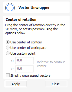
This tool converts one vector into another vector that can be used with the two-rail scanning tool to create rotational models from a desired cross-section.
To unroll the vector, follow these steps:
- Select the contour you want to unroll
- Use the options or the slide handle to select the center of unpacking
- Press Apply
The generated contour can now be used with the two-rail scanning tool to create rotary models.
Note
This tool is only available in rotary projects.
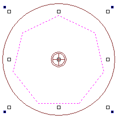

Center of Rotation
The center of rotation for the unwrapping changes the unwrapping of the contour so that when the resulting contour is used to create a rotary model, the center of rotation of the model is the chosen point.
Use center of contour
Sets the center of rotation to be the center of the bounding box of the selected contour
Use center of workspace
Sets the center of rotation to be the center of the workspace.
Use custom point
Sets the center of the job to be a specified point. The custom point can also be chosen by selecting the drag handle and dragging to the desired point.

Refine unwrapped vectors
Typically the resulting unwrapped contour will contain a large number of nodes. Selecting this option will result in an unwrapped contour with far fewer nodes.
Measure - Inspect
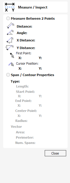
The Measure tool allows you to find important information about your model or drawings.
Watch this video to see this in action:
Measure Between 2 Points
With this option selected, you can click on two points in the 2D View and the form will report the measurements between the clicked locations
Distance
Straight line distance between the two points.
Angle
The angle (in degrees) of the line joining the two points, where horizontal is zero degrees and vertical is ninety degrees.
X Distance
The separation between the two clicked points in X only.
Y Distance
The separation between the two clicked points in Y only.
First Point
The precise X and Y coordinates of the position first clicked.
Cursor Position
The dynamically updated coordinates of the mouse cursor position.
Span / Contour Properties
This mode allows you to find precise information about the individual spans of a vector shape in 2D View. Use your mouse pointer to click on any part of the shape and the information relating to the entity you have clicked will be displayed on the form.
Type
The type of span you have clicked.
Possibilities include:
- Line
- Arc
- Bezier Curve
Length
The length of the clicked span.
Start Point and End Point
The precise coordinates of the node forming the start and end of the selected span.
Vector
Information relating to the whole vector, of which the selected span is part, is shown in this section.
Area
The total area of the selected vector
Perimeter
The total length of all the spans forming the perimeter of the shape
Num. Spans
The total number of spans in the shape.
Post-Processor Management
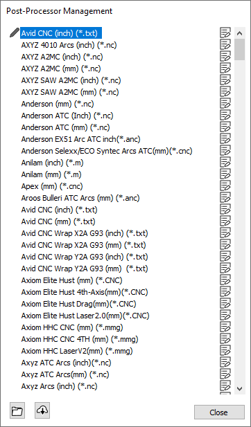
The Post-Processor Manager dialog can be accessed either from the Machine menu on the main menu bar, or from within the Machine Configuration Management dialog when a new Associated Post-Processor is selected.
Post-Processors are text files containing the instructions used to translate an Aspire toolpath into the format required by any one of the many types of machine tool and controller supported by our software. The Post-Processor Manager dialog lists all of the currently available post-processors provided and maintained by Vectric and allows you to select one or more to use with your machine tool. You can also directly view the instructions contained within a particular post-processor - and see any updates or changes that may have occurred between versions. If necessary, you can create and customise your own post-processor based on the most closely related one already available in the Manager.
Inspecting a Post-Processor
Each post-processor in the Manager can be inspected to see what changes have occurred between versions, what the specific underlying instructions contained in the post-processor are and they can be used as the basis of a new, custom, post-processor of your own.
You can click on the Inspect icon next to each post-processor in the list (or right-click the post-processor name) to open the command list.

There are several commands available for the provided post-processors.
View Post-Processor Instructions
Selecting from the Inspect icon command list will bring up the Post-Processor Content dialog for the selected post-processor.
View log of changes between versions
Selecting from the Inspect icon command list will bring up the Change Log dialog for the selected post-processor.
Creating a custom post-processor
The command from the Inspect icon command list creates an editable copy of a post-processor that can be used to make an entirely bespoke post-processor of your own.
Your own, customized, posts always appear at the top of the Post-Processor Management list and are indicated with a pencil icon to distinguish them from those provided and maintained by Vectric.

Inspecting a custom post-processor
The Inspect icon, and right-click, commands list is different for a custom post-processor than for a post-processor provided and maintained by Vectric.
You can open your custom post-processor in any text editor in order to edit it to your specific needs. The file is stored in a special My_PostP folder locally on your computer. For convenience the command in the Inspect icon commands list will open your file explorer at the correct location for you find all of your custom post-processors.
Note:
Custom post-processor files in your My_PostP folder have a files suffix of *.pp by default, but they are plain text files and can be opened in any basic text editor including the Notepad, installed by default by Windows.
Similarly the command from the Inspect icon command list provides a convenient way to delete a specific custom post-processor file from your My_PostP folder.
Warning:
Deleting a file from this folder in this way is not reversible.
Install a custom post-processor from file
Custom post-processor files can be installed automatically into your My_PostP folder using the Install Post-Processor icon at the bottom of the Post-Processor Manager window.

Clicking on this icon will allow you to browse to the file on your computer. Double-click on the file to select and install it. Once installed the post-processor will appear at the top of the Post-Processor Manager window with any other custom post-processor you have created or installed.
Update the Post-Processor List from the Cloud
If you are connected to the internet and logged in to your V&Co account you can use the Update Post-Processor List button at the bottom of the Post-Processor Management window to get the latest list of all of the post-processors provided and maintained by Vectric.
Note:
Updating the post-processor list from the cloud will not affect your own, customized, post-processor (which are retained in your My_PostP folder). By default, maintained post-processors for your machine may include updates, but previous versions are always available and can be explicitly locked in your Machine Configuration. Refer to the Machine Configuration management section for more information on this.
08. Intermediate - Creating a Rotary Job
Z Origin
You have the choice of specifying if the tool is being zeroed on the center of the cylinder or the surface. When you are rounding a blank, you cannot set the Z on the surface of the cylinder, as the surface it is referring to is the surface of the finished blank. We would strongly recommend for consistency and accuracy that you always choose 'Center of Cylinder' when outputting wrapped toolpaths as this should always remain constant irrespective of irregularities in the diameter of the piece you are machining or errors in getting your blank centered in your chuck.
Tip:
A useful tip for doing this is to accurately measure the distance between the center of your chuck and a convenient point such as the top of the chuck or part of your rotary axis mounting bracket. Write down this z-offset somewhere, and zero future tools at this point and enter your z-offset to get the position of the rotary axis center. Another reason for choosing 'Center of Cylinder' is that some controls will be able to work out the correct rotation speed for the rotary axis based on the distance from the center of rotation. If the Z value is relative to the surface, the control would need to know the diameter or radius of the cylinder at Z zero.
XY Origin
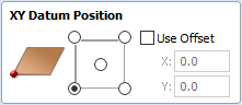
XY Drawing Origin - Here you can specify where the XY zero origin will be placed on your job. These options correspond to the same fields on the normal 'Job Setup' form within the program. Most people would use the default Bottom Left Corner, but for some jobs you may prefer to have the XY origin in the Center.
- In a job with horizontal orientation (Along X Axis), the X offset will correspond to the length of the cylinder, and the Y offset will be a point along its circumference.
- In a job with vertical orientation (Along Y Axis), it's the opposite. The Y offset will correspond to the length of the cylinder, and the X offset will be a point along its circumference.
Orientation
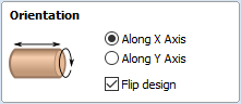
Cylinder Orientation Along - This section is used to tell the program how you have your rotary axis aligned on your machine. If you've already made your design, but just want to change the job for a different machine, then you could flip your design with the material so that all the vectors and components stay the same relative to the job.
Z Origin On - This section determines whether the Z Origin is set to the surface of the material or the base (center of cylinder). These settings can be over-ridden when the toolpath is actually saved, but we would strongly recommend the 'Cylinder Axis' is selected for rotary machining. The reasons for this are detailed in the note below.
Vector Layout
As well as creating a job at a suitable size for wrapping toolpaths, when creating the job, it will create a number of vectors which can be very useful when creating your wrapped job.
The vectors are created on their own individual layers and by default these layers are switched off to avoid cluttering up your work area. To switch on the layers, display the 'Layer Control' dialog (Ctrl+ L is the shortcut to show / hide this). To show / hide the layer simply click on the check box next to the layer name.
2Rail Sweep Rails - This layer contains two straight line vectors which can be used to sweep a profile along if you are creating a shaped column.
Bounding Box - This layer contains a rectangular vector covering the entire job area. This vector is useful if you are going to machine the complete surface of the cylinder.
Choosing stock material
When setting-up rotary project, software assumes a perfect cylinder with an exact diameter. In practice the stock material may be uneven, or only blank with square profile may be available. In those cases blank needs to be machined into cylinder of desired size, before running toolpaths associated with the actual design.
Another consideration is length of the stock material. Typically, part of the blank will be placed within the chuck. It is also important that during machining, the cutting tool is always in safe distance from both chuck and tailstock. For those reasons, the blank has to be longer than the actual design. When setting-up the machine for cutting, one has to pay extra attention to ensure that origin is set accordingly to avoid the tool running into chuck or tailstock!
If the design was created without those considerations in mind, the blank size can always be adjusted in the Job Setup form.
The picture below presents an example of a rotary project layout. As explained above, the actual blank is longer than job defined in Aspire to allow for the chuck and sufficient gaps. The actual design is shorter than job defined in Aspire, to leave some space for tabs, that can be machined with the profile toolpath prior to removing the finished part from the chuck.
When machining 3D shapes with varying thicknesses like on the example shown below, it is a good idea to place the thicker end of the model on the side closest to the driving motor. This way torsional twisting will mostly affect the stronger end of the machined part and help to avoid bending or breaking of the part during machining.
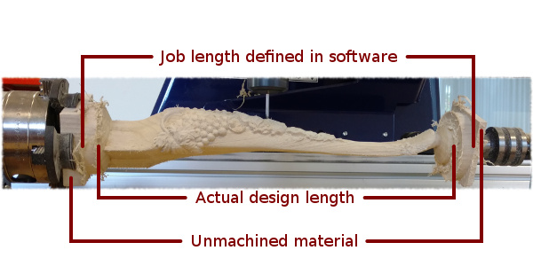
Recalculate All Toolpaths
This command forces a recalculation of all the toolpaths in the Toolpath list. It is useful when the artwork used by the toolpaths has been modified, or the material block settings have changed.
View
| Zoom to Drawing | Use when you need to see the whole drawing and material as large as will fit in the 2D View window. |
F5 | Refresh 2D View | In situations where the complete vector geometry represents a very large job and the user zooms into a small region, the shape of arcs and curves may look faceted. This is only a display issue and will not impact on the quality of toolpaths. This command will rebuilds the display information to correct the graphics being drawn on the screen so curves are drawn smoothly again. |
| Guide Lines ► | For more details see the section on Rulers, Guidelines and Snapping. Opens the Guide Lines sub-menu. |
| Draw Origin | XYZ origin arrows can be toggled on and off in the 3D View to show exactly where the X0, Y0 and Z0 origin is position is relative to the material. |
| Draw Modeling Plane | This option controls the display of the semi-transparent 'modeling plane' which shows the position of the working model base plane. |
| Draw Material Block | Toggles the drawing of a wireframe representation of the limits of the material block. This is useful for seeing how the 3D model will be positioned in the block of material it is being cut from. |
= | Multi Sided View | Allows you to view both sides in the 2D and 3D view when working in a multi sided environment. |
| Auto-Wrapping View | Allows you to view wrapped toolpaths and models when in rotary job. |
| Color Shaded View | Draws / Undraws the color shaded job in the 3D window. |
| Use Shaded Background | Shows either the default gradient filled color background or a solid light blue color background. The solid color is very useful for saving images that need to be cropped out of the background in a graphics software package. |
| Light follows viewer | The default light setting for the 3D window shines a light onto the job from the top left corner of the material bounding box. Checking ✓ this option can sometimes be used to help visualize the job more easily. |
| Use Shadow Shading | Toggles the drawing of increased shadows in the 3D view. This can be useful for emphasizing details in models. This degree of shading can be increased or decreased using Ctrl + NumPad+ or Ctrl + NumPad- ( Please note that this option will not be available for double sided or Rotary jobs, where shadowing on modeling plane would not be realistic) |
| Save Shaded Image | Saves a color shaded image of the 3D view as a BMP, JPG, PNG or GIF file. Note Saving the image without the color shaded background is often useful when the image will be used on its own in a brochure or on a web site etc. If you select PNG as the file type with the shaded background switched off the image will be saved with a transparent background. To switch the shading off, go to Edit ► Options ► Use Shaded Background and set Use Shaded Background to No. |
Page Down | Tile Windows Horizontal | Tiles the 2D and 3D View Horizontally, 2D View at the top and 3D at the bottom. |
Page Up | Tile Windows Vertical | Tiles the 2D and 3D View Vertically, 2D View on the left and 3D on the right. |
| Cascade Windows | Cascades the 2D and 3D View so they overlap. |
Guide Lines sub-menu
| Guides Visible | Toggles the visibility of Guide Lines in the 2D view. |
| Delete All Guides | Deletes all the Guide Lines in the 2D view. |
| Lock All Existing Guides | Locks the position of all the Guide Lines in the 2D view. |
| Unlock All Existing Guides | Allows all the locked Guide Lines in the 2D view to be moved again. |
Keep-out Zones
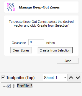
Keep-out Zones are used to define areas of your material which it is not safe for a tool to pass through or over.
These can be used to represent hold downs such as clamps or screws which are protruding above the material and could damage tools should they collide.
Clearance vs Safe height
Keep-out zones will operate on Clearance height moves where the tool is being moved between toolpaths. Once a toolpath is completed, the tool will raise to the Safe Z Home height as set in the "Z Gap Above material" which is found in the Material Setup form and travel to its Home location. Ensure this Z Gap Above material is set high enough to clear clamps or other obstacles.
Watch this video to see this in action:
Zone Creation
Any vectors selected to represent areas where the machine should not pass over for the Keep-out Zones will need to be closed vectors.
If a vector you want to select for the Keep-out Zones is an open vector you will need to make it a closed vectors before selecting it, you can do this by using one of the close or join vector options in the Design tab.
Clearance
Enter a Clearance value if you need to extend the Keep-out Zone area beyond the area covered by the selected vectors.
Clear Zones
Use this to de-select all currently active Keep-Out Zones
Create from Selection
Create the Keep-out Zones from the currently selected Vectors, with the applied Clearance Offset.
Once created, Keep-out Zones are not linked to the Vectors used to make them and will remain even if the vectors are deleted.
Toolpath Warning
If a toolpath is created which intersects a Keep-out Zones, then you will see a warnings in the 3D View and also get a warning popup to alert you of this.
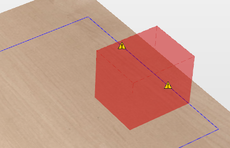
Ungroup Selection
Ungroup a set of Grouped vectors back to its individual vectors before it was grouped.
The Shortcut key for this operation is U.
Ungroup to the group's layer
By default, when grouped objects are ungrouped they revert to the layers on which they had previously been located before the grouping operation. However this is sometimes inconvenient. For example, when you have copied a group of vectors to a new layer, it is easier for subsequent editing if the copied vectors to remain on the new layer, even after ungrouping. An alternative right-click pop-up menu command has been added to make this process easier.
A shortcut key combination is also available to provide support for both of the ungroup operations. In summary, therefore, the group and ungroup shortcut options are as follows:
- GGroup the selected objects
- U Ungroup the selected objects to their original layers, sub-groups remain grouped.
- Ctrl + U Ungroup the selected objects to the group's layer, sub-groups remain grouped.
- Shift + U 'Deep' ungroup the selected objects to their original layers. Sub-groups are also ungrouped.
- Ctrl + Shift + U 'Deep' ungroup the selected objects to the group's layer. Sub-groups are also ungrouped.
Watch this video to see this in action:
Usable In Both Views
This tool can be used in both the 2D and 3D View.
2D View offers a more direct way to view your vectors while 3D Offers more flexability to work with Vectors in 3D Designs and to make use of the Edit Boxes.
Array Copy
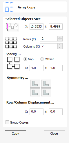
This tool will automatically create copies of the selected object and lay them out in a grid pattern. The grid size is determined from the number of row and columns requested and the spacing of the object copies can be set directly as a gap distance, or in terms of an offset distance between each copy's position.
Watch this video to see this in action:
Selected Objects Size
Reports the current size of the selection that you are intending to block copy. This is for information only, but the values can be selected, copied and pasted to use in other calculations.
Rows and Columns
These options specify how many rows and columns of the selected object to create. The total number of copies made will be X multiplied by Y.
Spacing...
There are two ways to specify the spacing between elements in array:
- Gap : The X and Y fields will be used to specify the gap between edges of each object copy.
- Offset : The X and Y fields are used to define the offset of the position of each object copy, relative to the preceding one.
Symmetry...
The symmetry area of the form gives you the ability to mirror and rotate objects. This allows for more advanced pattern making, by default the block symmetry form is set so there is no symmetry or rotation. To alter the pattern you can simply press the block symmetry buttons to create your desired pattern.
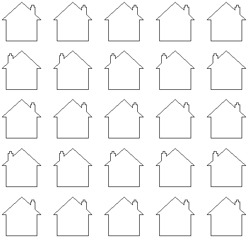
Row/Column displacement...
Entering values in the Row/Column displacement allows you to offset every other row or column by the value specified.
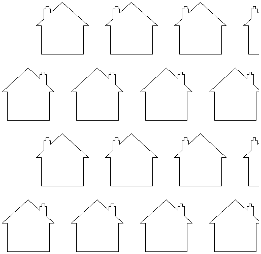
Group Copies
Having this option checked ✓ will group the objects that you have created in the form when you hit the button.
Usable In Both Views
This tool can be used in both the 2D and 3D View.
2D View offers a more direct way to view your vectors while 3D Offers more flexability to work with Vectors in 3D Designs and to make use of the Edit Boxes.
Copy Operation
The Copy tool copies selected objects to the clipboard, leaving the original in place and allows duplicates to be made and re-used in the design by pressing the Paste icon. Only one item can be Cut or Copied at a time.
File
New | Creates a New Aspire job. | |
| New from template... | Creates a new job based on existing Aspire job template |
Open... | Opens an existing Aspire job | |
| Close | Closes the current file but leaves the software running |
Save | Saves the current Aspire file over the last saved version of the file. Note This command will overwrite the old file with any changes made since the last save. If you are not sure of your changes then use the File ⇒ Save As... command instead option and give the file a new name. | |
| Save As... | Opens the standard File Save dialog so you can save the current file with a new name. |
| Save As Template... | Opens the standard File Save dialog so you can save the current file as a job template. |
| Increment and Save | The Increment and save operation allows you to automatically number iterations of files you are working on. If you select this operation when editing a file which ends with an underscore, or a hyphen followed by a number, then the number will be increased by 1 and the file will be saved using this number. For example, MyFile_1.crv3d becomes MyFIle_2.crv3d MyFile-1.crv3d becomes MyFile-2.crv3d Note The increment and save option will keep incrementing until it finds a file that does not currently exist. It will not overwrite an existing file. |
| Opens the Print Setup box to Print your design | |
| Print Preview | Displays a Preview of the design to print |
| Print Setup | Opens the Print Setup box to Print your design |
| Import... ► | Import various entities into the job |
| Export... ► | Export vectors from the job |
| Open Application Data Folder... | Opens the Windows folder where files used by the software are stored. This is useful for adding to the default files installed initially. Application files include: Bitmap textures for creating custom materials. Gadget scripts for customized automation of the software. Postprocessors The Tool Database Default toolpath strategy settings Vector texture files. |
| Exit | Closes the job and exits the software. |
Import
Import Vectors / Bitmaps... | Import Vector or Bitmap data. | |
Import Component / 3D Model... | Import 3D Model or Component | |
| Import PhotoVCarve or Cut3D Toolpaths... | Import a toolpath file created in another Vectric application, such as, Cut3D or PhotoVCarve. |
Export
Allows you to export selected Vectors as either an eps, dxf, ai, svg or pdf format vector file. If no vectors are selected, the all visible vectors will be exported.
- EPS
- DXF
- AI
- SVG
Note
When exporting in DXF format, the layer information relating to the exported vectors is preserved.
Printing and Print Preview
The contents of either the 2D or 3D view can be printed using the Print... command on the File menu. Simply select the view you wish to print (2D or 3D) and then click the Print... command. The standard Windows printer dialog allows you to select the printer and adjust its properties. When the OK button in this dialog is clicked, the view will be printed. To adjust the printer settings without printing, you can open the same dialog using the Print Setup... command on the File menu. When used in this way, the button on the dialog will store the settings without printing immediately.
Note
By default printing the 3D view does not print the shaded background; this behaviour can be changed using the Options dialog, which is opened using the Options command on the Edit menu.
The Print Preview... command on the File menu allows you to check the layout of your page before you print. If you are happy with the preview, use the button to begin printing the document directly from the Print Preview page.
Note
The printed view is always scaled to exactly fit the currently selected page size (including allowance for margins). Drawings are not, therefore, printed at actual size and are not printed across multiple pages.
Drilling Toolpaths
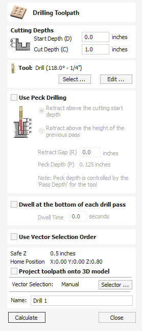
Drilling allows the centers of selected closed vectors to be drilled to a specified depth. The Tool Database includes an option to specify the Drill diameter and cutting parameters.
Watch this video to see this in action:
Cutting Depths
Start Depth (D)
This specifies the depth at which the toolpath is calculated from.
When cutting directly into the surface of a job the Start Depth will often be 0. If machining into the bottom of an existing pocket or 3D region, the depth needs be entered.
Cut Depth (C)
The depth of the toolpath relative to the Start Depth.
Tool
Clicking the button opens the Tool Database from which the required tool can be selected. See the section on the Tool Database for more information on this. Clicking the button opens the Edit Tool form which allows the cutting parameters for the selected tool to be modified, without changing the master information in the database. Hovering the mouse cursor over the tool name will display a tool tip indicating where in the Tool Database the tool was selected from.
Peck Drilling
When the option Use Peck Drilling is selected, the drill will cut to the Pass Depth set in the Tool Database for the selected Drill. It will then retract to the Retract Gap according to the retract option selected (see below), before drilling to the next depth, incremented by an additional Pass Depth. This cycle is repeated until the hole is drilled to the required depth. The retract moves are used to remove any build-up of material from the hole to help with overheating and breakage. If the Pass Depth is greater than the required Cut Depth, the hole will be drilled in a single cycle. However, if a Cut Depth of 1 inch with a Pass Depth of 0.25 inch is used the hole will be drilled in 4 cycles.
Retract above cutting start
This option will cause the tool to retract fully out of the drill hole after each peck drill plunge. This is beneficial for clearing swarf/chips completely from the drill hole during the drill cycle. With this option selected the Retract Gap value (R) is the fixed distance above the start cut depth. Thus the total retract and plunge distances for each peck drill cycle will increase as the hole deepens and this will generally result in longer machining times.
Retract above the height of the previous pass
Instead of fully retracting out of the drill hole, it is also possible to retract to a height relative to the previous cut depth. This strategy typically requires a shorter set of plunges and retracts over the course of a peck drill toolpath because they will be constant for each peck drill cycle, regardless of the drill hole depth. However, it will not necessarily clear swarf/chips completely from the drill hole. With this option selected the Retract Gap value (R) is the relative distance above the height of the previous peck drill pass.
Dwell at the bottom of each drill pass
With this option checked, ✓ the Dwell Time value is used pause the drill at the bottom of each peck drill pass before retracting. The dwell time value is measured in seconds.
Note
To make use of this feature your Post-Processor must support the Dwell section and may require updating.
Use Vector Selection Order
If this option is checked, ✓ the vectors will be machined in the order you selected them. If the option is not checked the program will optimize the order to reduce machining time.
Position and Selection Properties
Safe Z
The height above the job at which it is safe to move the cutter at rapid / max feed rate. This dimension can be changed by opening the Material Setup form.
Home Position
Position from and to that the tool will travel before and after machining. This dimension can be changed by opening the Material Setup form.
Project toolpath onto 3D Model
This option is only available if a 3D model has been defined. If this option is checked, ✓ after the toolpath has been calculated, it will be projected (or 'dropped') down in Z onto the surface of the 3D model. The depth of the original toolpath below the surface of the material will be used as the projected depth below the surface of the model.
Note:
When a toolpath is projected onto the 3D model, its depth is limited so that it does not exceed the bottom of the material.
Vector Selection
This area of the toolpath page allows you to automatically select vectors to machine using the vector's properties or position. It is also the method by which you can create Toolpath Templates to re-use your toolpath settings on similar projects in the future. For more information, see the sections Vector Selector and Advanced Toolpath Templates.
Name
The name of the toolpath can be entered or the default name can be used.
Clearing or Splitting Components
The options to clear areas of a 3D Component, inside and outside of vectors or to slit a vector into multiple pieces are very useful modeling tools. There are many occasions where the standard modeling options may not allow you to create or control the exact shape that you need. Often you may need to create the general shape then crop (cookie cut) the resulting Component either to leave just the part of the shape you want or to make a hole in it. Many examples of this will be covered in the video tutorials supplied with the software.
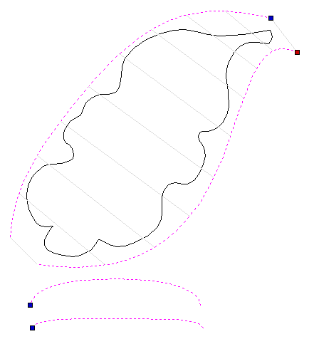
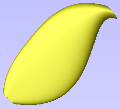
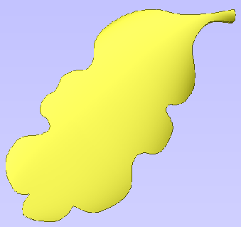
In the image above and left you can see the vectors selected for a 2 Rail Sweep to make a simple flowing shape. The result of this sweep is shown in the middle image. Our actual leaf edge vector can be seen in the left hand image after cropping the swept shape back to the leaf outline vector.
To use the cropping function you need to select the Component or Components you want to edit first and then select the object last that you want to use as the cropping region. If multiple Components, or a Component group, are selected for this tool, Aspire will prompt for you to bake the Components before continuing. See Baking Component for more information.
Clear Component Inside Selected Vectors
Removes the contents of the 3D model that is inside the currently selected object.
Clear Component Outside Selected Vectors
Removes the contents of the 3D model that is outside the area of the currently selected object.
Split Component
This tool allows you to split the selected Component into two independent Components. To use this tool, you must select the Component you wish to split and a single vector to indicate the split boundary then click on the icon.
You can use either an open or closed vector to define the split boundary. A closed vector can be envisaged as a 'cookie cutter'. The resulting two Components will be as if the cookie cutter vector was pushed through the selected Component to split it.
If an open vector is used to define the split boundary, Aspire will extrapolate from the ends of the selected vector to the edge of the modeling area to create the two resulting split Components.
The names of the resulting Components are automatically appended with '- A' and '- B' in the Component tree.
If multiple Components, or a Component group, are selected for this tool, Aspire will prompt for you to bake the Components before continuing. See Baking Components for more information.
View Controls
Your project is represented using 2D and 3D workspaces, each viewed via independent windows; the 2D View and 3D View, respectively. This division usefully maps to the typical workflow in which you will initially focus on the 2D design and layout of your project before moving to the 3D stage of modeling, toolpathing and previewing your finished part.
You can switch between the views using the tabs at the top of each window. In addition the shortcut-keys F2 and F3 will toggle the display between the two windows.
It is sometimes useful to see both the 2D and 3D representations at the same time. The Page Up and Page Down keys will arrange the 2 views either horizontally or vertically so you can see both workspaces simultaneously. To return to the tabbed display, simply click on the standard Windows Maximize button in the top right corner of either view window.
Many of the controls for manipulating the view in your project are similar in both 2D and 3D.
From within each view you can also directly interact with the objects that make up your job using the Object Selection Tools.
Merged Toolpath
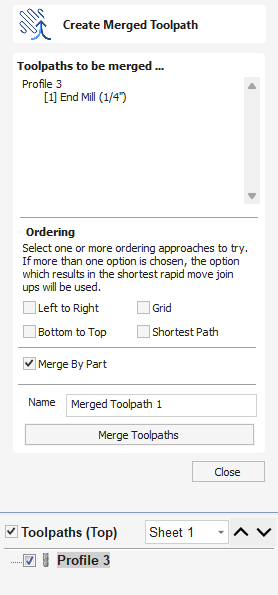
When using the same tool for different types of toolpath (eg. Pocketing and Profiling) those toolpaths can be merged to create a single toolpath which performs the same cutting operations more efficiently.
Toolpath Selection
The toolpath merge tool will always try to merge all visible toolpaths. To toggle the visibility of the toolpaths click the corresponding check boxes for each toolpath in the toolpath list shown below the form. The toolpaths to be merged will appear in the box marked Toolpaths to be merged...
Ordering
The toolpath merge tool has a number of checkboxes which allow different orderings of the resulting merged toolpath. When the toolpaths are merged each of these ordering strategies is calculated and the quickest strategy chosen.
Merging by Part
When the Merge By Part check box is selected, the toolpath merge not only tries to optimize the whole toolpath, it also tries to group related geometry to cut together.
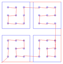
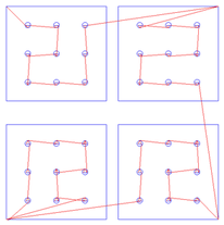
Merging by part tries its best to respect the ordering of the toolpaths in the toolpath list, and the order of contours within a given toolpath. In particular, if contours of two different toolpaths lie within the same part, the contour of the first toolpath will be cut before the contours of the second toolpath. The following examples show how the toolpath order in the main toolpath list alters the results of toolpath merging.
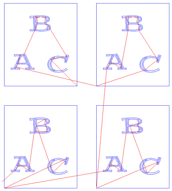
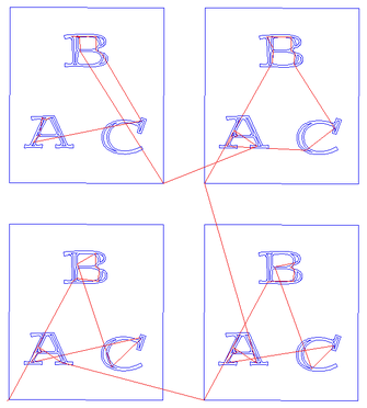
Toolpath Name
Enter a name for the newly created merged toolpath.
Feeds and Speeds
It may be that the toolpaths to be merged have different feeds and speeds. Toolpath merging will automatically change the feeds and speeds for the different parts of the toolpath but you should check that your post -processor supports this.
Material Setup - Flat
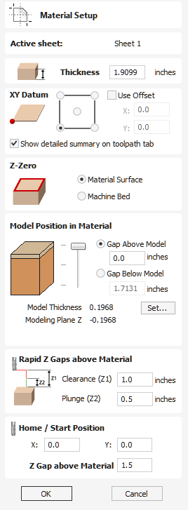
Active Sheet
This shows which sheet is currently selected and what sheet you are adjusting the Material Setup for.
Thickness
Enter the thickness of the material being machined.
Show detailed summary on toolpath tab
This checkbox toggles the Material Setup summary layout on the Toolpaths tab between simple and detailed views.
Side Z-Zero
Select relative to the Material Surface or relative to the Machine Bed. This is a very important setting because the tooling used on the CNC machine must be setup in the same way, ensuring the toolpaths cut to the correct depth.
If you are working in a 2 Sided job, this will set the Z Zero for your current side only,
- The side you are setting up will be displayed in brackets e.g. (Top).
- You can set the Z-Zero for both sides through the Job Setup form.
Model Position in Material
The thickness of your model must be less than the thickness of the material you wish to cut it from. You can position your model within the material block wherever you wish by defining the gap distance either above or below your model. You can also double left click on either of the three lines next to the slider to position the model at the top, center or bottom of the material.
Note for Two-Sided Jobs
The gaps defined here are for the entire combined models from both sides (i.e. the final result you see when two-sided view is enabled). The above / below gaps do not depend on which side you are currently on. They represent the whole 2 sided model as if viewed in the correct orientation.
Gap Above Model
This distance positions your model according to the gap between the top of your model and the top surface of the material.
Gap Below Model
Alternatively you can position your model by defining the gap between the bottom of the model and the bottom surface of the material.
Model Thickness
This field simply reports the thickness of your composite model (as built from all your currently visible components).
Scale Model Height
The button can be used to change the Z Height of the Composite 3D Model (the visible Components) if it is not an appropriate height for your material thickness. Clicking this button will open the Set Model Height form which allows you to enter a new value for the overall height of the combined Components. After you have entered a new value hit and visually check the 3D model to ensure it still looks correct. Once you have found an appropriate value that looks good you can hit the button to continue in the Material Setup form. This height scaling function is also available from the Scale z height of model icon on the modeling toolbar.
Modeling Plane Z
Once you have positioned your model, this field will tell you the new height of your modeling base plane. This is for information only, and results from the gap settings above and cannot be edited directly.
Rapid Z Gaps above Material
Clearance (Z1)
This is the height above the job at which it is safe for the cutter to move at rapid or maximum feed rate. The software will raise the bottom of the cutter to this height when it traverses the material.
Plunge (Z2)
For all toolpaths, as well as specifying a rapid clearance gap for rapid positioning moves above the workpiece, the user can also specify a much smaller gap that the tool will rapid down to during plunge moves. By default the plunge gap is set to the same value as the Clearance gap which means that there will be no rapid plunges. If you set the plunge gap to a smaller value than the Clearance gap, the tool will plunge at rapid feed rate to the specified distance above the material surface before changing to the specified plunge rate. For jobs where a large value for Clearance gap has to be specified to avoid clamps etc, this feature can save a considerable amount of machining time if there are a lot of plunge moves in the job.
Note
Some engraving machines are not able to take advantage of this feature.
Home / Start Position
This is the absolute position that the tool will start moving from and where the tool can be programmed to return to at the end of cutting the job.
This allows you to chose a Start and Park position for your Spindle to return to should you want
Extrude and Weave
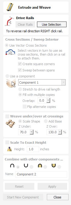
The Extrude and Weave feature is a very powerful and flexible modeling tool. It uses one or more vector drive-rails to define the path that the shape will follow, this allows you to extrude either vector cross-sections or 3D Components along these vectors to create the model.
The first stage is to select the drive rails and then choose whether you want to use either vectors or Components to extrude along your curves. There are many options both on the form and under the context sensitive right-click menus that can be used to control the shape that is created.
Watch this video to see this in action:
Drive Rail Selection
From the 2D View use the mouse to select one or more open or closed vectors you wish to use as the drive rails for you to extrude or weave along. Then click the button.
In the 2D view your rail vectors will be highlighted orange and now show a green square (start node) indicating the start of the vector from which the extruded shape will begin, and arrow markers along its length to show the direction of the extrusion.
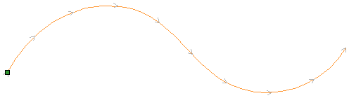
The default start point and direction shown may not be what you intended. To change the direction, right-click with the cursor on the vector line and select Reverse Rail from the context sensitive menu, you will now see the arrows on the drive rail change direction. On a closed vector you can change the start point by placing the cursor over an existing node in the drive-rail vector, right-clicking and selecting Make Start Point or you can right-click anywhere on the vector and select Insert Start Point to create a new node which will become the start point.
Note
Remember that you can hold down a Shift key while left-clicking on vectors in the 2D view to include more than one vector in the selection.
The button can be used at any time to empty your current selection. This will delete your current shape and deselect all the drive rail and cross section vectors. This can be used if you do not want to create a Component before you exit the form or if you want to select new vectors in the 2D view to use as the drive rail for your shape.
Using Vector Cross Sections
In this section of the form you can select whether to use vector cross sections or Components to extrude along your drive rails, select either Use Vector Cross Sections or Use a Component to make your choice.
Cross Section Selection
The next step is to select one or more cross-section vectors to sweep along your rails to form a 3D shape. In order for vectors to be used as valid cross-section shapes, they must be open.
Select a vector that you wish to use as a cross-section in the 2D View by left clicking on it with the mouse.
If you are using just a single cross section then you just need to make sure it is selected and then can proceed with the other settings in the form and calculate your shape. If you want to edit cross section positions or add more than one cross section then you will need to attach them to the drive rail.
Select a vector that you wish to use as a cross-section in the 2D View by left clicking on it with the mouse. Now click on the drive rail to attach the cross-section to that vector.
As you move the mouse over a selected drive rail it will indicate with a check mark ✓ that it is a valid place to add the cross section. Once a cross-section has been successfully attached to your drive rail, the 2D view will show a preview using line markers to indicate how the cross section will be positioned when it is extruded.
Two Cross-Sections are always created when you attach the first cross-section to the drive rail - one at the start and one at the end. The intermediate lines along the entire length of the rail indicate how the shape will flow between the defined cross sections. You can click the button to create your 3D swept shape.
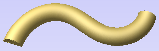
Using multiple cross-sections
It is possible to extrude between multiple cross section vectors along a drive rail blending from one vector shape to another.
Adding Cross-Sections
To add a new Cross-Section to an existing extrusion, simply select an open vector in the 2D View that you wish to use as a cross-section. With the vector selected, click on the point along the rail to which you wish it to be attached. A new Cross-Section will be inserted at this point. On applying the change, the resulting 3D sweep will blend seamlessly between all the defined Cross-Sections along the rail.
Note
To help differentiate which cross section is being used at each location the software will indicate a colored node at one end of each cross section and place the same colored node on the preview position. This node also indicates the direction the cross section is being 'hung' across the curve. The same cross section vector can be used in multiple locations along the drive rail.
In some cases it may be advantageous to add a cross section at all node positions on a drive curve, for example on a closed rectangular border. This can either be done manually, or automatically after you have added the first Cross-Section by right-clicking on the cross section you wish to duplicate and selecting Add To All Rail Nodes. This will add that same cross section to every node on that specific drive rail vector.
Removing Cross-Sections
To remove a Cross-Section, position the cursor over the cross section and click the right mouse button. Select the option to Delete Cross Section from the menu.
If you remove the start or end Cross-Section and fail to replace them with a new cross-section vector then the preview will no longer show intermediate lines to that point on its length. This means the shape will start or stop at that cross section and not go all the way to the start/end of the line. You can either add a new cross section or drag an existing one to that position if you need to resolve this.
You can remove all the Cross-Sections on a drive rail by positioning the mouse arrow over a part of the curve that does not contain a cross section. This will bring up a different context sensitive menu and you can select the options to Remove All Cross Sections.
Create sharp corners
If this option is checked, ✓ then the tool will create a sharp corner in the Component where there are discontinuities in the drive rail vector. When unchecked the shape will be rounded as it goes around the discontinuity. Below you can see a rectangular drive curve with a simple cross section being extruded around it, the one on the left has the Create sharp corners option selected and the one on the right without.
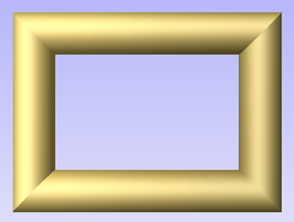
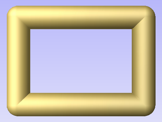
Sweep between spans
When checked ✓ this option will ensure that as the shape is extruded that it goes from a particular span/node in one cross section to the same span/node on the next cross section. For some applications this can give the user more control over the way the shape flows.
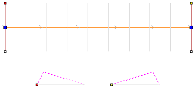
Using the above vector selection, the shape below left will be created with Sweep between spans checked ✓ and the shape on the right is created with the option un-checked. Note that on the left hand picture the crease in the shape goes from node to node in the cross sections as the spans flow exactly from one to the next. On the second picture the shape just linearly flows from one cross section to the next evenly with no additional control.
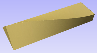
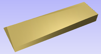
Smooth transition through the Cross Sections
As the extruded shape passes through each cross section the default is for it to flow smoothly through the profile. This can be edited by right-clicking over a cross section and unchecking the Smooth option. The middle node on the cross sections preview in the 2D View will be blue if it is smooth and white if it is un-smooth.
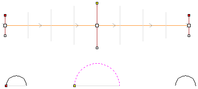
Using the above vector selection, the shape below left will be created with the Smooth option checked ✓ and the shape on the right is created with the option un-checked. Note that on the left hand picture the shape flows smoothly through each span, on the second it goes directly from cross section to cross section in a straight transition.
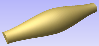
Extrude and Weave Components
The Extrude and Weave feature also allows the option to use a 3D Component instead of using vector cross sections to define the shape being created. To activate this feature choose the Use a Component option under the Cross Sections / Sweep Interior section of the form.
Once this option has been selected then you need to select a single Component that will be used for the operation. This can only be done within the form and not from either of the views or the Component Tree. Use the arrow at the side of the name in the drop down list to access a list of all the Components and select the one you want to use. By default the first Component name in the Component Tree will be shown in this section of the form. If the form is opened with a single Component selected, the selected Component will be the default in the list. Once selected a preview of the extrusion will be shown in the 2D view.
The orientation of the Component in your part will control how it flows along the vector. The direction along the X-axis of your Component will govern how it flows positively along the drive curve. Another way to think of it is you need to position your Component so it faces from left to right to orient how it will point along the curve.
Once your Component has been selected from the list you need to choose whether it will be used as a single copy stretched along the curve or repeated multiple times at its original size.
Stretch to drive rail length
Picking this option will take a single copy of the Component and stretch it along the full length of the selected drive rail vector.
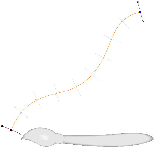
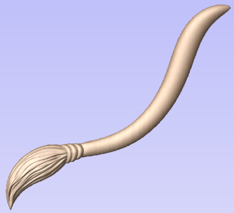
Fill with multiple copies
Selecting this option will keep the Component at its original size and repeat it along the drive curve. Specifying an Overlap value will set each copy of the Component to overlap the previous one by this percentage of its length. Each overlapping piece will be merged together. In addition to overlapping the parts you can also check ✓ a box to flip alternate copies of the Component. This will flip every other copy of the original as if it had been mirrored vertically.
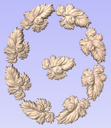
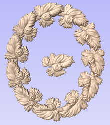
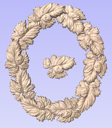
Weave under/over at crossings
With either vector or Component based extrusions you have the option to activate the Weave part of the function. This gives the ability to raise and lower the extruded shape at positions where the drive rail vector or vectors cross over. The effect of this is a Component that appears to be weaving the extruded shapes as you can see below.
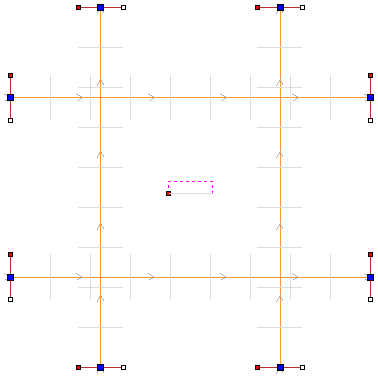
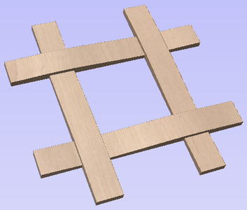
The order of the weave is determined by the direction of the first vector picked as part of the drive-rail selection. To change the order of which overlapping positions are raised up and lowered you can right mouse click on the first drive rail vector you selected and choose the option.
There are two options to control the way the shape is scaled at each overlapping point in the drive rail vectors, Scale Shape and Add Base.
Scale Shape
The Scale Shape option uses the percentage values entered into the form to scale the height of the original shape up and down at the cross-over positions. For example entering a Z Under percentage of 50% will force the locations which are being weaved under to be half their original height. Entering a Z Over percentage of 150% would force the locations of the shape which are being raised as they weave to be 1 ½ times their original height. This will distort the cross sections or Components to stretch or squash them.
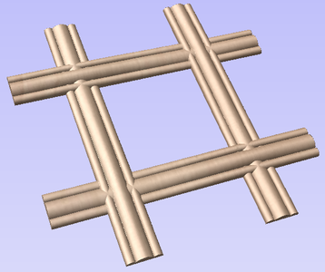
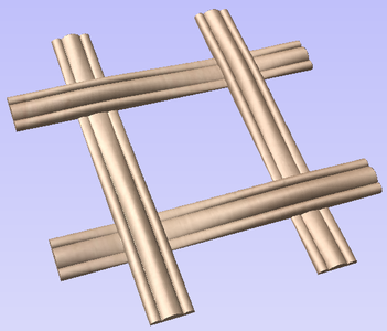
The Scale Shape option will give a natural looking weave but for certain shapes will mean the detail in the shape may become heavily accentuated or reduced at the overlaps. In these situations the Add Base option may create a better result.
Add Base
The Add Base option will retain the height of the original cross section or Component and raise it up adding material under the shape depending on the percentage values indicated. This will typically create a higher final Component than using the Scale Shape option but gives a consistent shape to the strands of the weave.
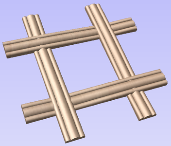
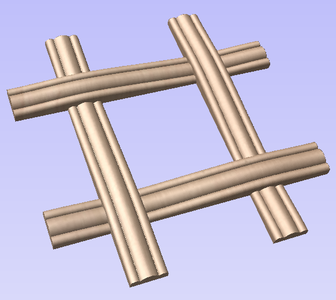
Scale to Exact Height
Checking ✓ this option scales the shape calculated so its maximum height is the value entered in the Height area of the form.
Common Modeling Options
All of the main modeling tools in the software use a common set of commands to assign a name and combine mode to the component being created along with options to apply the settings in the form, reset the shape, start creating a new component and close to exit the function.
Combine with other components...
This section includes options to allow you to name your Component and control the way it will be combined with other objects in the Component Tree.
Reset
Clicking the button will remove the current shape, doing this before you Close the form will ensure that a component is not created from the current selection. Clicking this does retain the current set of selected vectors or Components.
Apply
Clicking the button will create a shape based on the settings you have chosen. You can continue making edits to the component by choosing different parameters within the form and hitting Apply to update it.
Start New Component
Clicking the button will save the state of the component that has been created, deselect all components/vectors and start the creation process again on a new component. The values and options within the form will be retained in this case until you Close it.
Close
Clicking the button will close the form returning to the Modeling Tab icons and the updated Component Tree, reflecting any changes that you have made. If you wanted to remove the shape you just created then you can hit the Undo icon or use the keyboard shortcut to undo, CTRL+Z.
Editing vectors while using the Extrude and Weave tool
It is possible to make edits to the vectors that you have selected while using the Extrude and Weave tool. To do this you can click in the whitespace of the 2D View to ensure you have focus on that window. Then on the keyboard hit either N to go into Node Editing mode or T to go into Transform mode.
You will notice the drive rails and cross sections will become deselected and the button will change to say . You can now make edits to the vectors using the dynamic Node Editing and Transform functions in the 2D view. When you are happy with your changes you can click on the button and the vectors will be selected in the same order they were before. Now you can click the button to create a new shape based on the edited vectors.
Create Shape - Round
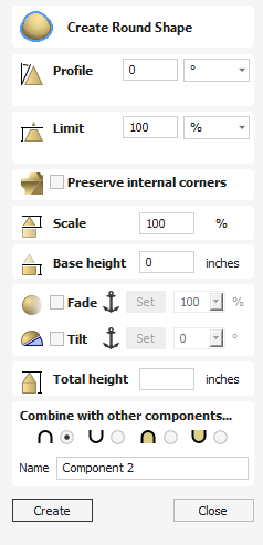
The Create Round Shape tool creates a rounded 3D model component.
Watch this video to see this in action:
Profile
The Profile setting will define the angle of the edge of the rounded shape - the higher the angle, the steeper the shape.
Limit
This will limit the height of the shape created. This can be entered in as a value or you can use the slider bar in the drop down menu.
Preserve Internal Corners
When creating a shape using both external and internal vectors, the resulting component will have both external and internal corners. In this scenario, with this option unchecked the internal sides of the resulting shape would curve into the centre line at which the two sides meet if you draw a straight line from the top peak of the corner to the base of the shape, creating rounded internal corners.
Enabling this option by checking the box will mean that these internal sides will be comprised of a completely straight sided skeleton until both sides converge at the centre line of the corner, creating a defined sharp crease and an internal corner which will come to a sharp point as if the corners have been perfectly mitred.
Note
A good way to visualise the effect of this is to imagine looking at a corner of a building where two separate wings with pitched roofs meet, you’d expect to see a straight faced slope rather than a bowed slopein the corner from the ridge to the eaves. With this option deselected the slope would be pinched and curved inwards towards a single point in the corner.
This is best demonstrated with examples that use a polygonal base vectors;
Scale
This limits the height of the shape by scaling the shape up or down while retaining its general specified profile. It is scaled to the height entered in the Height area of the form which becomes available once this option is selected. The slider can also be used to change the final height.
Base Height
Specifies the height of a flat 'base plane' added below the profile you have chosen.
Fade
When this option is checked ✓ the user can fade the Z depth of the Component. The first part of this operation (once the option is checked ✓) is to select the Set Anchor button - then click two points in the 3D view. The first click specifies the point which will remain at the current height. The second click specifies the point that the Component will be faded down toward. The shape will fade down from the first point to the second by the percentage selected.
Change the strength of the fade by clicking the down arrow next to the percentage value and using the slider to move this up and down or type in a specific value for the amount you would like to reduce the depth by. The fade will be applied linearly between the two selected points. This is a useful tool for giving the effect of a Component fading into the distance to help with overlapping areas of Components if you want to lower an area to give it the appearance of going behind another one.
Tilt
When this option is checked ✓ the user can set a direction and angle to tilt the shape up at an angle in Z. The first part of this operation (once the option is checked ✓) is to press the Set Anchor button - then click two points in the 3D view.
The first click specifies the point which will remain at zero (the pivot point of the tilt).
The second click specifies the point that will be tilted upwards by the specified angle (the point that will be raised up).
The angle can be edited by clicking the arrow next to the value and using the slider or by typing in a specific value and hitting the Space Bar on the keyboard to apply the angle.
Total Height
This is the Total height of the model and this will change when editing the Profile, Limit, Scale or Base Height options.
If you edit the height this will also edit the value in the Scale and Base Height section to create the shape at the correct height entered.
Combine with other component
This section includes options to allow you to name your Component and control the way it will be combined with other objects in the Component Tree.
Search for Machine Online
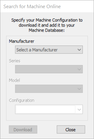
The search for a machine online feature give you the ability to download a post file that matches your machine in both make and model, and also layout if rotary axis are present on your machine.
There are two ways to begin a search. Either start a job and then go to Machine > Search for a machine online or you can access the search for the machine online through the Machine Configuration Management by clicking the Search for a machine online icon. Also if you have no other machines loaded when you try and save out a toolpath file you will be prompted to perform an online search as well.
Once you have started the search a percentage bar will appear which will go to 100% once the initial download has been completed. Internet speeds may vary in the time this takes.
Once done you may see a message warning you that you are about to update your list of post processors and you will be given a or option to continue.
By clicking a box will appear with a number of drop down lists allowing you to choose the following options:
Manufacturer:
The company that made your machine.
Series:
This will typically bring up a few options for the overall series of your machine i.e. the name your manufacturer has given it.
Model:
Typically model will refer to the size of your machine as some manufacturers may make more than one size of machine in a series.
Configuration:
In some cases the only options will be a default one but for some machines that have a rotary axis you can define if the axis is on the X or the Y. If you are choosing a rotary axis it is critical that you select the correct orientation of your machine as this will have a big effect on the result.
VTransfer
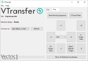
VTransfer is a small helper application provided by Vectric to simplify the process of sending toolpaths to some Grbl-based controllers. You should run VTransfer on the PC which your CNC machine is connected to via a USB serial connection.
If your Vectric CADCAM software is also running on the same PC, you can use Direct Output mode to send toolpaths to VTransfer directly from the Toolpath Saving form, without the need for file saving or loading.
VTransfer also provides the commands you need to initiate basic homing, jogging and setting of origins on your CNC machine before a toolpath is run.
Controllers
VTransfer has been created specifically for streaming toolpaths to a pre-configured controller. It expects that your controller is correctly set-up and tested for your hardware. VTransfer will not set, alter or validate your controller's parameters in any way and is not intended to be used for lower-level controller configuration.
Getting Started
Before starting VTransfer, you need to ensure that your machine is powered on, any required drivers are already installed and the machine is accessible via a serial port (COM port on Windows). For most machines connected by USB, you will need to have installed the appropriate device driver for your machine controller. These drivers will be provided by your machine tool supplier and you should verify that your CNC machine connects correctly to your PC before attempting to use VTransfer.
When the machine and drivers have been installed correctly, refreshing and checking the drop-down Connect On: list will show your machine tool controller. VTransfer will still need to know the specific communication protocol required though and the first time you use VTransfer you will need to complete some one-time set-up and configuration.
Once set-up for a machine that remains connected to the same USB port of your PC, VTransfer should automatically detect and connect each time it starts-up.
Initial Set-up
Once this initial set-up has been completed, VTransfer should automatically detect and connect to your machine on start-up, provided the machine remains connected to the same USB port of your PC. Before connecting to your machine for the first time, however, you should complete the following steps to set the right controller type and maching configuration.
- Select File->Settings from the main menu to open the Settings
- Make sure that your controller is selected in the Controller Name: drop down list (for a Grbl version 1.x controller this will be Grbl, for example)
- Select the correct configuration file for you machine, or create your own.
Controller Connection
- Make sure that your machine is connected to the PC via USB and it is powered on
- Click the button, regenerate the Connect On: drop down list with all of the detected devices connected to your PC.
- Select your controller device from the list - note that this may be the name of the microcontroller on which your controller is running, rather than the controller name itself (grbl may appear as Arduino UNO, for example)
- Check that the Machine Status reported by VTransfer reads Looking for... followed by the expected controller name
- Machine Status will change to Connecting while VTransfer attempts to verify the controller is communicating as expected
- Once correct communication has been established the Machine Status will change to Initialising, Alarm or Ready depending on how your machine is configured
Running a toolpath
Once connected to your CNC machine, the typical steps for running your first toolpath using VTransfer are:
- Open the Jog Tab
- If your Machine Status is Locked, either or Unlock your machine (if supported and configured)
- Load your toolpath file or send one to VTransfer via Direct Output
- If required, jog the machine to the location of the material on your CNC machine (to match the relative origin point of your toolpath) and set the
- Fit the required tool
- Either run the Z Touch Plate cycle (if supported) to set Z Zero to match your toolpath
- Or manually jog the tip of the tool to the material surface or machine bed (again to match the Z Zero setting of your toolpath) and set the
- Ensure the spindle is on (if it is not controlled automatically)
- Open the Cut Tab - Click
Sending a toolpath directly to VTransfer from your Vectric software
At the point of saving your toolpath some post-processors support the option of Direct Output to VTransfer (such as the Emblaser or X-Carve). If you have one of these post-processors selected, the Output direct to machine checkbox will be enabled below the post-processor selection box in the Toolpath Saving form.
With this box checked, will change to and clicking this button will automatically send the toolpath to VTransfer. If VTransfer is not already running, it will launch automatically.
Whenever a new toolpath is loaded or received by VTransfer it will prompt you with a message box.
Homing, Jogging and Origins
Before running your toolpath, it is essential to set your machine's origins appropriately. The specific process you need to use will, to a large extent, will be determined by your machine and its configuration. Generally you will need to home your machine (if supported) and set the X Y origin to match the intendended toolpath and location of the material on your machine's bed. You will also need to fit the correct tool and typically set the tip of this tool to be at Z Zero, either at the top or bottom of your material - again this choice will already have been determined when your toolpath was created. The commands relating to these actions are all available from the Jog tab.
Whenever VTransfer changes its origin settings you will be prompted with a message box.
Start Homing Sequence
Click this button to initiate the homing sequence. The homing sequence will culminate in setting the origins of your machine using its homing switch locations and the machine's machineable area - both of which are set in the configuration. For some controllers (such as Grbl) you will typically be required to run this command before you can do anything else because the machine will start-up in a disabled Alarm status.
Note
This button is only available if your machine is configured with homing switches and homing is enabled.
Z Touch Plate
This button will be visible if your machine is configured with a touch plate, touch plate support is enabled and its thickness is set in the configuration settings. Click it to initiate the Z touch plate probing cycle. Make sure that the touch plate is in position and correctly functioning before clicking this option as it will immediate begin a plunge move.
Warning
Make sure that the touch plate is in position and correctly functioning before clicking this option as it will immediately begin a probing plunge move.
Jogging
The , , , , and buttons will each jog the machine along the Y, X or Z axes, respectively.
The distance moved by each button click is determined by the current value (in mms) shown in the drown-down control at the center of the jogging buttons. Ensure that you adjust this value appropriately before using the jog buttons to move the machine.
Lasers
If the selected configuration for your machine has a Z travel value of zero, this indicates that the machine does not have a Z axis - this is the case for most laser cutters - and Z axis controls will not be visible.
Setting and Resetting Origins
By default a machine with homing support will have its X Y origin (the postion of the coordinate X:0 and Y:0) set to the bottom left corner of machine's machinable area following a homing cycle - i.e. the machine will operate in a positive coordinate work space within its machinable area. For machines without homing support, the initial X Y origin must alwaysbe set manually before running a toolpath. In additon, when a toolpath is created it is very common that the X Y origin will actually be chosen to be relative to the material (not the machine bed) - for example, the center of a design may be used. For most toolpaths, therefore, you will need to jog the machine to the matching origin location for the toolpath (relative to your material), and manually before cutting.
For machines with homing support, you can restore the bottom left corner origin after setting it for a specific toolpath by clicking at any time. When this button is clicked the location of coordinate position X:0, Y:0 will once again be set to the bottom left corner of the machine's machinable area.
Running the Toolpath
The Cut tab contains the controls need to begin cutting your toolpath and monitoring its progress.
Cut Now
When your machine is correctly set-up (with the X,Y and Z origins set), click this button to begin streaming the toolpath to your machine and begin cutting.
Warning
Make sure your machine spindle is on before clicking this button if your spindle control is manual.
Estimated Time Remaining
Once your toolpath has started, VTransfer will provide a dynamic estimate of the remaining time until the toolpath is finished.
Dynamic Feedrate Override
If your machine supports feedrate override control and the option is enabled in your configuration, then the and buttons will be available. Click these buttons to increase or decrease the current toolpath feedrate by 10%. The current state of the feedrate override setting is indicated by the percentage value between the two control buttons.
Delay
Depending on the nature of the toolpath you are running, there may be a delay of one or more seconds before your machine responds to the feedrate change so allow for this when using these controls.
Abort
This button will stop the toolpath as quickly as possible, usually resetting the controller in the process. Once a toolpath has been aborted you should re-home and re-origin before running a subsequent toolpath.
Pocketing Toolpath
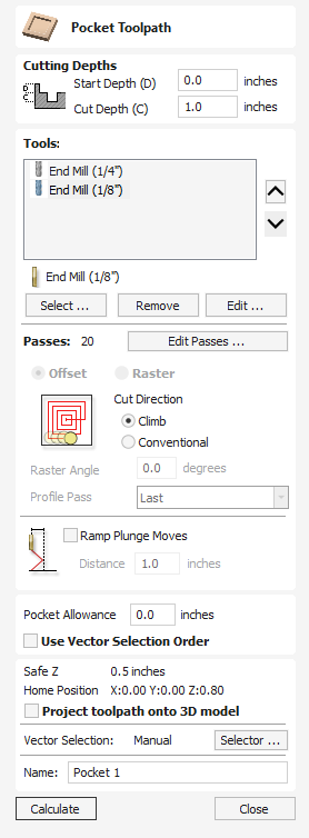
The Pocket toolpath is used to remove large areas of material. It removes the areas contained inside the selected vectors.
Watch this video to see this in action:
Cutting Depths
Start Depth (D)
This specifies the depth at which the toolpath is calculated from.
When cutting directly into the surface of a job the Start Depth will often be 0. If machining into the bottom of an existing pocket or 3D region, the depth needs be entered.
Cut Depth (C)
The depth of the toolpath relative to the Start Depth.
Tool Selection
In the pocketing toolpath you can select any number of tools you wish to use to perform your pocketing. When multiple tools are chosen then the first tool removes as much material as it can, all subsequent tools in the list will remove as much material as it can from any previously unmachined areas. If multiple tools are selected then the order of the tools in the list should match the order they will run on the machine.
Note
An allowance will always be left on for the final tool to remove.
Clicking the button opens the Tool Database from which the required clearance tool can be selected and added to the list.
Clicking the button will remove the selected tool from the list.
Clicking the button opens the Edit Tool form which allows the cutting parameters for the selected tool to be modified, without changing the master information in the database.
Clicking the up and down arrow buttons will move the selected tool up and down the list respectively.
Pass Depth Control
When a toolpath is created, the Pass Depth value associated with the selected tool (part of the tool's description) is used to determine the number of passes needed to profile down to the specified Cut Depth. However, by default the software will also modify the precise step down by up to 15% in either direction, if by doing so it is able to total number of passes required to reach the desired cut depth. It is nearly always desirable to benefit from the significantly reduced machining time of cutting using less passes if possible. Nevertheless, there are some occasions where the exact step down for a given profile pass needs to be more precisely controlled - when cutting into laminated material, for example. The Passes section page indicates how many passes will be created with the current settings.Thebutton will open a new dialog that enables the specific number and height of passes to be set directly.
Specify Pass Depths
The Pass Depths section at the top of the form shows a list of the current pass depths. The relative spacing of the passes is indicated in the diagram next to the list. Left click on a depth value in the list, or a depth line on the diagram, to select it. The currently selected pass is highlighted in red on the diagram.
To edit the depth of the selected pass, change the value in the Depth edit box and click .
The button will delete the selected pass.
The Passes button will delete all the passes.
To add a new pass, double left click at the approximate location in the passes diagram that you wish to add the pass. A new pass will be added and automatically selected. Edit the precise Depth value if required and then click .
The Set Last Pass Thickness option will enable an edit box where you can specify the last pass in terms of the remaining thickness of material you wish to cut with the last pass (instead of in terms of its depth). This is often a more intuitive way to specify this value.
Pass Depth List Utilities
Note
Setting the number of passes with either of these utilities will discard any custom passes you may have added.
The first method simply sets the passes based on the Depth of Step property of the selected tool. By default, this is the method used by Aspire when initially creating profile passes. However, if the Maintain Exact Step Depth option is checked, the software will not vary the step size to try to optimize the number of passes (see above).
The second method creates evenly spaced passes based on the value specified in the Number of passes edit box.
To apply either method, click the Set Associated Passes button to create the resulting set of pass depths in the pass list and diagram.
Strategy Options
There are two choices of the type of fill pattern that will be used to clear away the area to be machined with the Pocket Toolpath, Offset and Raster.
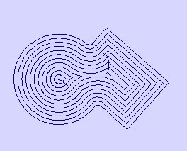
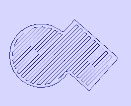
Offset
Calculates an offset area clearance fill pattern to machine inside the selected vector(s). Options for Cut Direction to be either: Climb (CCW) cutting direction Conventional (CW) cutting direction.
Note
When the stepover for a pocket fill is greater than 50% of the cutter/tip diameter the software automatically adds 'Tail' moves to the corner regions on the toolpaths to ensure material is not left on the job. You can see these in the diagram of a star being pocket machined below:
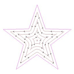
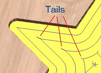
Raster
Calculates a Raster based area clearance fill pattern to machine inside the selected vector(s). Cut Direction only applies to profile pass and can be either:
- Climb (CCW) cutting direction
- Conventional (CW) cutting direction
Raster Angle
Between 0 and 90°, where 0° is parallel to the X axis and 90° parallel to the Y axis.
Profile Pass
Used to clean up the inside edge after machining the pocket. This can be done either before the rastering (First) or after the rastering (Last). If 'No Profile Pass' is selected, you will need to calculate a profile pass manually to machine the pocket to size.
Note:
When using multiple tools, selecting 'No Profile Pass' option will cause subsequent tool to machine areas that otherwise would have been cleaned up by the profile pass
Pocket Allowance
This option is used to leave material on the inside of the pocket for the Profile Pass to clean-up. This is often very useful for ensuring the cutter does not mark the edge surface of the pocket when roughing out.
Ramp Plunge Moves
The cutter can be ramped over a distance into the pocket instead of plunging vertically. This approach reduces heat build-up that damages the cutter and also reduces the load on the spindle and z axis bearings.
Use Vector Selection Order
If this option is checked, ✓ pockets will be machined in the order you selected them. If the option is not checked the program will optimize the order to reduce machining time.
Position and Selection Properties
Safe Z
The height above the job at which it is safe to move the cutter at rapid / max feed rate. This dimension can be changed by opening the Material Setup form.
Home Position
Position from and to that the tool will travel before and after machining. This dimension can be changed by opening the Material Setup form.
Project toolpath onto 3D Model
This option is only available if a 3D model has been defined. If this option is checked, ✓ after the toolpath has been calculated, it will be projected (or 'dropped') down in Z onto the surface of the 3D model. The depth of the original toolpath below the surface of the material will be used as the projected depth below the surface of the model.
Note:
When a toolpath is projected onto the 3D model, its depth is limited so that it does not exceed the bottom of the material.
Vector Selection
This area of the toolpath page allows you to automatically select vectors to machine using the vector's properties or position. It is also the method by which you can create Toolpath Templates to re-use your toolpath settings on similar projects in the future. For more information, see the sections Vector Selector and Advanced Toolpath Templates.
Name
The name of the toolpath can be entered or the default name can be used.
Subtract Vectors
Selected closed vectors that overlap can be merged together to create a new shape. These tools consider the closed vectors to be solid areas.
The following examples begin with these five vector shapes where the rectangle was selected last.
Areas in the first shapes that overlap the last selected shape are removed. In this case, the last selected shape was the rectangle, so the rectangle is cut away from the circles anywhere that overlaps.
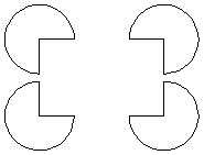
Watch this video to see this in action:
Usable In Both Views
This tool can be used in both the 2D and 3D View.
2D View offers a more direct way to view your vectors while 3D Offers more flexability to work with Vectors in 3D Designs and to make use of the Edit Boxes.
10. Advanced - Rotary Machining and Wrapping
Aspire can 'wrap' flat toolpaths around a cylinder to provide output to CNC machines which are configured with a rotary axis / indexer. The image below shows a flat toolpath wrapped around part of a cylinder.
Note
It is important to note that wrapping works in conjunction with specially configured post-processors which take the XYZ 'flat' toolpaths and wrap them around a rotary axis, replacing either the X or Y moves with angular moves.
The toolpaths can be visualized wrapped within the program when the Auto Wrapping mode is on.
Aspire can also visualize a wrapped model within the program by drawing the shaded composite model wrapped.
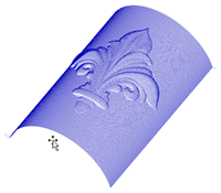
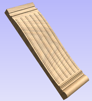
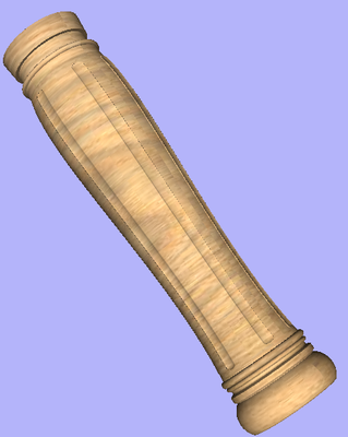
Aspire also has the ability to draw the toolpath simulation wrapped. Although this is very useful for getting a feel for how the finished product will look, it is important to realize that the wrapped simulation may not be a 100% accurate representation of how the finished product will look. An example of potential difference would be if you drilled holes in your rotary job. In the actual work piece these will obviously just be round holes, in the wrapped simulation these may appear as distorted ovals due to the 'stretching' process which takes place when we wrap the flat simulation model for display.
Note
If your rotary axis is aligned along your Y axis you would choose the Orientation Along Y Axis option during job setup. All the examples in this document will assume that the rotary axis is aligned along X.
It is important to realize that there are a huge number of possible combinations of machine controller and axis orientations for rotary axis / indexers. This means it is impractical for Vectric to supply a pre-configured post-processor for every possible combination as standard. We include some wrapping post-processors in the software that can be configured when you setup your Machine Configuration.
If you need to select a new post, you can do so by accessing the Save Toolpaths menu. To do so, click the 'Manage machine configuration' button as seen in the image below:
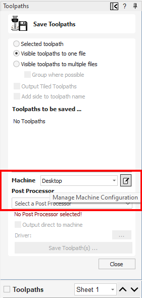
This will now open a menu where you can press the button under 'Associated Post-Processors' to access all of the available post-processors within the software and choose the appropriate wrapped post-processor for your machine configuration.
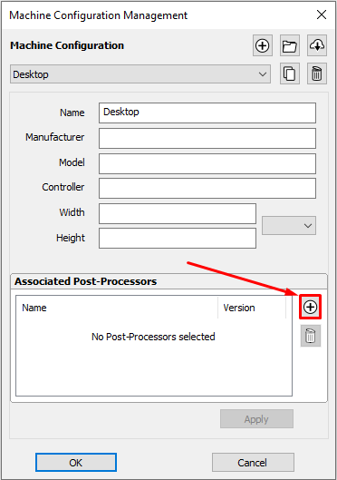
You can also right click the post in this menu and select 'view' to view the contents of the post, should you need to edit it later.
Examining these posts may be helpful if you need to configure a post of your own. If Vectric have not supplied a standard a post for your machine configuration please refer to the Post Processor Editing Guide accessible from the Help menu of the program for information on how to configure a post-processor and also look at the standard rotary posts Vectric supply.
You should also look at the Vectric forum to see if anyone else has already configured a post for your configuration or one similar. If, after looking at these resources you are still unsure of what needs to be done for your machine, please feel free to contact support@vectric.com for help. However, please note that we cannot guarantee to write a custom rotary post-processor for every individual requirement.
Import Component / 3D Model
This opens the File Open dialog window and allows image files to be selected and imported into the current open job. File types - BMP, JPG, TIF, GIF, PNG
Images are imported to sketch vectors over the top of them, generate traced vectors or to be used to generate a 3D Component directly from the image. These functions will be covered in more detail in the
Convert text to Curves
Converts selected text object into vector form, creating lines, arcs and Bezier spans that can be interactively edited. After conversion the text cannot be edited as a text object.
In most cases all the text created in Aspire can be VCarved, Engraved, Pocketed and Profile machined or used with the 3D modeling functions without converting to the curves.
Some fonts do occasionally include loops and problems that need fixing using the Node Editing tools before it can be utilized for other functions.
Usable In Both Views
This tool can be used in both the 2D and 3D View.
2D View offers a more direct way to view your vectors while 3D Offers more flexability to work with Vectors in 3D Designs and to make use of the Edit Boxes.
Sheets Tab
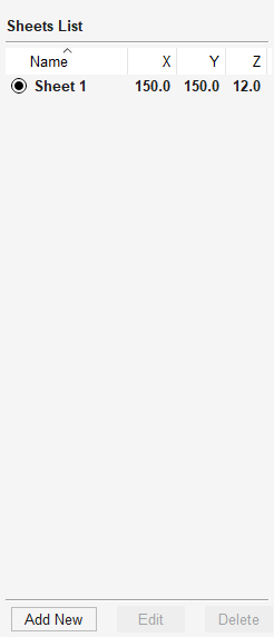
The sheets tab allows for the creation and management of separate sheets within a project. Each sheet can have independent dimensions and properties.
By clicking on the sheets tab you will see that you start with a single sheet.
Activation
When you have multiple sheets, you can switch between them either by double-clicking the button, or by double-clicking on the faded sheet preview from the 2D View. You can also do so from the Toolpath Tree filter list.
Please note that only one sheet at a time will be displayed in the 3D view.
Add New (Sheet)
This will create a new sheet.
If you have a sheet selected, it will duplicate the selected sheet. If not, it will duplicate the active sheets dimensions.
Multiple Sheets
You can select multiple sheets and click 'Add Sheet' to create the same number of sheets as duplicates.
Sheets will appear in the 2D View unless made invisible.
Edit
Edit Sheet-Specific properties using the Sheet Editor form where sizes can be altered along with the Z-Zero position and then datum for that sheet.
Delete
Delete the selected sheet(s). You must have at least one sheet in the project.
Visibility
Control the visibility of the sheet in the 2D view and other places to help clear up the view from temporarily unused sheets.
Tool Database - Cloud Version Selector
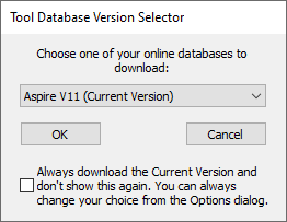
The Tool Database backups are kept separate for each major version (e.g. V10, V11, etc..). If you've recently upgraded from an older version (from V10 at least), you will not have your backup for the new version set up yet. This dialog will pop up the first time you attempt to download a backup.
It gives you the list of versions which you could download from. Those are the versions (products and versions) for which you've previously backed up your data for.
You can choose to not show this version selector again and always download the backup for your current version, which is most likely what you want to do.
Sheet Management
The sheet management tab can be used to add, edit, and delete sheets.
Add Sheet
New sheets can be added by clicking the button at the bottom of the tab or by right clicking and selecting Add New.
Making a Sheet Active
A sheet can be made active by double-clicking it either on its name in the Sheet list or on its Gray Outline in the 2D View. The title of the active sheet will be shown in bold, and its outline will be shown in the 2D view.
Editing Sheets
Sheet properties can be edited individually by right-clicking on the sheet and selecting Edit. This will open up the Edit Sheet Form where you can edit the sheet. You can also click the Sheet Name once and then click the Button at the bottom of the Sheet Form.
Multiple sheets can be selected at once in the sheets tab. To select more than one sheet hold down CTRL and click on the sheet to add the sheet to the selection. Once you have multiple sheets selected then they can be edited by right-clicking and selecting Edit or by using the button at the bottom of the tab. Changes made in the Edit Sheet form will apply to all selected sheets.
Removing Sheets
Sheets can be deleted from within the tab by selecting the sheet name and pressing at the bottom of the Sheet Form, or Rigth click on the Sheet Name and select Delete in the Right click menu.
Multiple sheets can be selected at once in the sheets tab. To select more than one sheet hold down CTRL and click on the sheet to add the sheet to the selection. Once you have multiple sheets selected then they can be deleted by right-clicking and selecting Delete or by using the button at the bottom of the tab.
Create a New File
This option opens the Job Setup form, which is used to create a new blank job of the specified dimensions and type. The relative origins for X0, Y0 and Z0 are also specified at this point, and the measurement units can be set in either inches or metric. The Modeling Resolution and default 3D shading color/material can also be set at this stage.
Create Shape - Plane
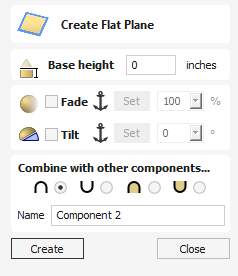
This will create a 3D model that is a flat plane.
Hold Shift when clicking this to create a Zero Plane the size of the material instead of creating a flat Component from any selected vectors.
Base Height
Specifies the height of a flat plane that you are creating.
Fade
When this option is checked ✓ the user can fade the Z depth of the Component. The first part of this operation (once the option is checked ✓) is to select the Set Anchor button - then click two points in the 3D view. The first click specifies the point which will remain at the current height. The second click specifies the point that the Component will be faded down toward. The shape will fade down from the first point to the second by the percentage selected.
Change the strength of the fade by clicking the down arrow next to the percentage value and using the slider to move this up and down or type in a specific value for the amount you would like to reduce the depth by. The fade will be applied linearly between the two selected points. This is a useful tool for giving the effect of a Component fading into the distance to help with overlapping areas of Components if you want to lower an area to give it the appearance of going behind another one.
Tilt
When this option is checked ✓ the user can set a direction and angle to tilt the shape up at an angle in Z. The first part of this operation (once the option is checked ✓) is to press the Set Anchor button - then click two points in the 3D view.
The first click specifies the point which will remain at zero (the pivot point of the tilt).
The second click specifies the point that will be tilted upwards by the specified angle (the point that will be raised up).
The angle can be edited by clicking the arrow next to the value and using the slider or by typing in a specific value and hitting the Space Bar on the keyboard to apply the angle.
Combine with other component
This section includes options to allow you to name your Component and control the way it will be combined with other objects in the Component Tree.
Laser Picture
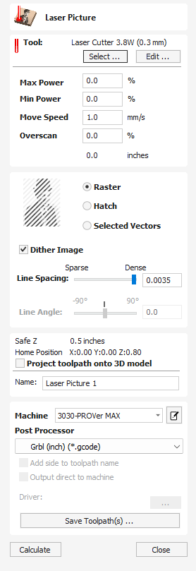
Note
The Laser Module is available as a paid-for add-on to the software. The features are not included in your software by deafult. To find out more about the Laser Module go to https://vectric.com/laser-module
The Laser Picture toolpath uses the laser to etch a copy of the selected bitmap picture into the surface of your material.
Tool Selection
Select Tool
This button opens your database of previously stored laser settings for different jobs and materials. When a setting is selected fromt the database it will be used to populate the key fields in this section. You can subsequenlty modify these values when calculating the laser toolpath. Modifying the settings on this form will not alter the original stored settings within your database.
Power
This value sets the proportion of the maximum laser power from your machines that will be used for this tool path.
Move Speed
This specifies the maximum speed that your machine will move during cutting or engraving moves. The units are determined by the database setting that was originally selected.
No. Passes
The machine can repeat a tool path several times to cut through thicker material. This value sets the maximum depth the machine will attempt to cut with each pass to achieve the final Cut Depth.
Overscan
Overscan allows the user to have the laser pass beyond the edge of the lasered area, to account for deceleration of the machine which would otherwise result in a darker edge to the laser burn. Overscan is machine dependant and the user will need to run some test images to identify how much overscan to use on their machine at a given feedrate to eliminate overburn at the edges of the lasered area.
Strategy Settings
Raster
Selecting this option will generate a single set of parallel lines, or stripes, across your selected image.
Hatch
This option will create two sets of parallel lines at 90 degrees from one another. This strategy will generally produce a denser image reproduction, but will typcially take twice as long to etch.
Selected
This option will use the selected vectors as the pattern for the toolpath moves. These may be generated using any method of creating vectors, such as the Vector Texture Tool
Dither Image
With this option un-checked, laser power will be changed evenly in response to the lighter and darker areas of your image. Thus your image is reproduced by a range of burnt tones onto the surface of your material using continuously varying laser power. For some materials, however, the burning process tends to produce only two tones - burnt or unburnt - rendering this graduated approach ineffective. For materials with this property an alternative strategy can be used to generate the tonal range using only black dot patterns of differing densities instead - much like old newspaper picture print. This process is called dithering and it can be enabled using this option. In general you should only use this option if the material properties prevent you from using the higher quality true grayscale method.
Line Spacing
This slider adjusts the gap between the raster stripes - tight striping produces a denser image reproduction, but will take a lot longer to etch. The maximum density is set by the Kerf of your laser beam and the most sparse setting is 30 times this value.
Line Angle
Adjust this slider to change the angle of the stripes or hatching used to etch the image. Zero degrees will produce horizontal stripes and ninety degrees, vertical.
Position and Selection Properties
Safe Z
The height above the job at which it is safe to move the cutter at rapid / max feed rate. This dimension can be changed by opening the Material Setup form.
Home Position
Position from and to that the tool will travel before and after machining. This dimension can be changed by opening the Material Setup form.
Project toolpath onto 3D Model
This option is only available if a 3D model has been defined. If this option is checked, ✓ after the toolpath has been calculated, it will be projected (or 'dropped') down in Z onto the surface of the 3D model. The depth of the original toolpath below the surface of the material will be used as the projected depth below the surface of the model.
Note:
When a toolpath is projected onto the 3D model, its depth is limited so that it does not exceed the bottom of the material.
Name
The name of the toolpath can be entered or the default name can be used.
Immediate Output
Once calculated, your toolpath is stored in the central Toolpath Tree and can be saved, edited or output to your machine at anytime using the command. In addition though, this form also includes a convenient Immediate Output section that allows you to save or send the most recently calculated toolpath directly from this form without having to close it.
Post Processor
Use this drop-down list to select the post-processor for your machine.
Add side to toolpath name
If you are creating aligned toolpaths for a two-sided part, this option automatically adds the side name to the toolpath name as it is saved or exported to help keep your toolpaths organised.
Output direct to machine
If your post-processor supports direct access to your cnc machine (including machines supported by VTransfer), this option will be available. Selecting this option will bypass saving the toolpath to disk and instead send it straight to the direct output driver.
Job Templates
Job templates are files which hold many frequently used dimensions, machine settings, or geometry. They are like regular .crv3d or .crv files apart from a few important differences:
- They have different file extensions (.crv3dt and .crvt)
- When they are opened into the software, then if you try and save them they will not overwrite the template, and they will behave as though they are new files being saved.
- The default save and load location is shared only across templates
The default location for existing templates is
C:\Users\Public\Documents\Vectric Files\Templates\Aspire V12.0
Creating a Job Template
To create a job template, create a job as you usually would, with the required dimensions, and machining setup. You can even add geometry that you want to form part of the template. Then click File > Save As Template and save the file in the desired location.
Using a Template
A template can be opened using the New file from template option on the start panel. Or alternatively from the File > New file from template top menu item.
Editing an Existing Template
To edit an existing template open it up in the usual way, and then save over the existing file using the File > Save As Template menu item.
Create Vector Boundary From Selected Components
This icon can be used to create a vector around the outermost boundary (silhouette) of one or more selected components. The most important use is to generate a vector that can be selected as a toolpath boundary, particularly for 3D Roughing, 3D Finishing and also Profile (cutout) toolpaths.
Aspire will create one or more closed vector boundaries around the edge of the selected components. If more than one closed vector is required to create the boundary, these will be created as a group to make it easier to select them. They would need to be ungrouped before they could be edited individually.
Mirror Mode
You can use this tool to create a vector boundary for a composition you have created in Mirror Mode. Simply select the components that are visible in the 2D View and apply the vector boundary.
Importing a 3D Model into Rotary job
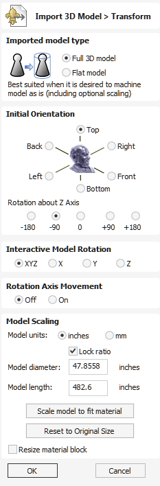
Imported model type
Allows the nature of the imported model to be specified. Depending on the selection, the form will change to allow the most appropriate workflow. You can choose from the following model types:
- Full 3D model - a model that is suitable for rotary machining as is,
- Flat model - a model that is only suitable as a part of design, similar to clipart provided with Aspire.
Initial Orientation
The purpose of this section is to roughly position the imported model within the material block. One can choose one of the 6 options to determine the most suitable direction on the model that defines the top surface (upper Z). This can be combined with one of the five options for Rotation about Z Axis.
Note
The software will try to guess the initial orientation that seems to be appropriate for the model, based on the model type selected in step one.
Interactive Rotation
This section can be used to fine-tune the model position in relation to the material block. The default choice XYZ-View allows the usual use of the mouse to rotate the 3D View, so the imported part can be seen from different angles. While this mode is selected, the orientation of the part will not change. Selecting one of the other four options above the word Model will enable adjustment of the actual positional orientation of the imported part. Choosing the XYZ option will allow rotation around all three axes simultaneously. Selecting X, Y or Z will only allow rotation around the specified axis. It will also automatically switch the 3D View to show the part from that axis.
Note
Selecting a different initial orientation will cancel any adjustments made by using Interactive Rotation.
Rotation Axis Movement (Full 3D model only)
This section can be used to adjust the position of the model in relation to the rotation centerline. By default Aspire will position the model in the center of the material block, so the material is used more efficiently.
When the Off option is selected, panning the 3D View will happen in the usual manner.
When the On option becomes selected, using the 3D View panning controls will move the rotation axis instead.
Model Scaling (Full 3D model)
This section allows the model scale to be adjusted as desired. The model bounding cylinder (blue) will be displayed around the imported model in the 3D View. The scaling is performed by means of length and diameter of the bounding cylinder. When the model orientation within the material block changes, so does the bounding cylinder. If that happens, the reported size of the model will change, although the model may not have been scaled.
Model units
By default Aspire assumes that the imported model is using the same units as specified during job setup. If that is not the case, the model units can be changed.
Note
If the model units are different than those selected during job setup, the imported model will be converted to use the units selected during job setup.
Lock ratio
When this option is selected, all scaling operations will maintain the current ratio between model length and diameter.
Scale model to fit material
This option can be used to resize the imported model so it will fit in the material block as defined during job setup.
Reset to Original Size
This option undoes any scaling applied to the model (apart from unit conversion), regardless of the model orientation.
Resize material block
When this option is selected, the project's material block will be resized to match the final dimensions of the imported model.
Model Scaling (Flat model)
This section allows the model scale to be adjusted as desired. A flat material block is displayed and the scaling can be performed by means of length in each of the three axes (X, Y and Z).
Model units
By default Aspire assumes that the imported model is using the same units as specified during job setup. If that is not the case, the model units can be changed.
Note
If the model units are different than those selected during job setup, the imported model will be converted to use the units selected during job setup.
Lock ratio
When this option is selected, all scaling operations will maintain the current ratio between the model length in each of the three axes.
Scale model to fit material
This option can be used to resize the imported model so it will fit in the material block as defined during job setup.
Reset to Original Size
This option undoes any scaling applied to the model (apart from unit conversion), regardless of the model orientation.
OK
Creates a 3D Component based on the settings in the form, the Component will have the same name as the imported file.
Cancel
Cancels the Import function and returns to the standard Modeling Tab icons.
Save Toolpath Template
Using the Toolpaths ► Templates ► Save Selected Toolpath as Template menu command (or the associated icon), all the settings for the currently selected toolpath can be saved as a template.
3D View Controls
| 3D Twiddle | Click and drag Right mouse button in the 3D window |
| Zoom | Mouse Middle Wheel - Rotate wheel |
| Pan | Click and drag Right mouse button and hold Ctrl. Click and drag Middle mouse button Click and Drag Left and Right Mouse buttons |
| Zoom to box | Zoom in to the selected area to fit within the current 3D View window. To select area click top left corner, hold mouse down and drag to bottom right corner and release |
 | Zoom to Fit | Zooms the whole 3D part to fit within the current 3D View window |
| Zoom to selection | Zooms in to the selected vectors or models to fit within the current 3D View window |
 | Orthographic or Perspective view | Toggle between Orthographic and Perspective camera projection |
 | Rotate around model (Rotary) | Rotate clockwise / anti-clockwise around the model (Available only in a Rotary project with Wrapped View). |
View Controller
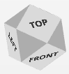
The View Control is the 3D Visual Orientation Control for rotating the 3D View quickly and easily.
To use it you can do the following.
- Click and drag it to smoothly rotate the 3D View with the Mouse.
- Highlight a face with the mouse, and click, to have the 3D View smoothly move to directly face that orientation.
- Double click a highlighted face to have the 3D View smoothly rotate to the opposite side of that orientation.
Material Setup - Rotary
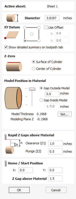
Active Sheet
This shows which sheet is currently selected and what sheet you are adjusting the Material Setup for.
Diameter
Enter the diameter of the material being machined.
Show detailed summary on toolpath tab
This checkbox toggles the Material Setup summary layout on the Toolpaths tab between simple and detailed views.
Z-Zero
Select relative to the surface of the material cylinder or its center. This is a very important setting because the Tooling used on the CNC machine must be setup in the same way, ensuring the toolpaths cut to the correct depth.
Model Position in Material
The diameter of your model must be less than the diameter of the material you wish to cut it from. You can position your model within the material block wherever you wish by defining the gap distance either outside or inside your model. You can also double left click on either of the three lines next to the slider to position the model at the top, center or bottom of the material.
Gap Outside Model
This distance positions your model according to the gap between the top of your model and the surface of the material cylinder.
Gap Inside Model
Alternatively you can position your model by defining the gap between the bottom of the model and the center of the material.
Model Thickness
This field reports the thickness of the model (as built from all the currently visible components). The model can be scaled by clicking on the button.
Modeling Plane Z
Once you have positioned your model, this field will tell you the new height of your modeling base plane. This is for information only. It results from the gap settings above and cannot be edited directly.
Rapid Z Gaps above Material
Clearance (Z1)
This is the height above the job at which it is safe for the cutter to move at rapid or maximum feed rate. The software will raise the bottom of the cutter to this height when it traverses the material.
Plunge (Z2)
For all toolpaths, as well as specifying a rapid clearance gap for rapid positioning moves above the workpiece, the user can also specify a much smaller gap that the tool will rapid down to during plunge moves. By default the plunge gap is set to the same value as the Clearance gap which means that there will be no rapid plunges. If you set the plunge gap to a smaller value than the Clearance gap, the tool will plunge at rapid feed rate to the specified distance above the material surface before changing to the specified plunge rate. For jobs where a large value for Clearance gap has to be specified to avoid clamps etc, this feature can save a considerable amount of machining time if there are a lot of plunge moves in the job.
Note
Some engraving machines are not able to take advantage of this feature.
Home / Start Position
This is the absolute position that the tool will start moving from and where the tool can be programmed to return to at the end of cutting the job.
This allows you to chose a Start and Park position for your Spindle to return to should you want
Save a File
This option opens the File Save As dialog window and allows the job to be saved as a Aspire file. Navigate to the required folder, enter a suitable name for the job and click the Save button.
You can also change the Save As Type using the Dropdown menu. This will allow you to save your file in the .CRV VCarve Pro file type. Saving with this file type will remove all 3D clipart and other 3D Data that is not usable in VCarve Pro, and will allow you to open a file from Aspire in VCarve Pro.
Alignment Tools
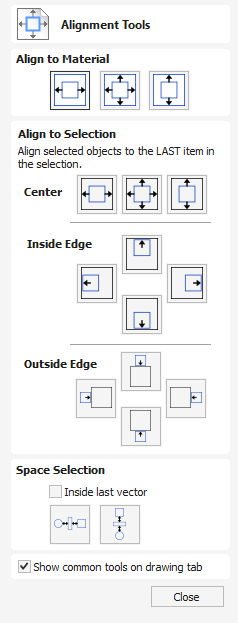
The Align Objects tool provides a number of options for accurately aligning the selected object to other objects in the selection, or to the available material.
Watch this video to see this in action:
Align to Material
The options in this section will align one or more selected objects within the material workspace defined when you setup your job (the white area in your 2D View).
Center in Material

This option moves the selected items to be positioned in the middle of the material. The short-cut key for this is F9.
Center in Material X only

Align items centrally in the material only moving them along the X axis so the vertical position will not be changed.
Center in Material Y only

Align items centrally in the material only moving them along the Y axis so the horizontal position will not be changed.
Align to Selection
The different items comprising your design in the 2D View can be aligned relative to one another using the following selection sequence:
- Select the item/s you wish to align / move (use single or multiple selection options).
- Hold the Shift key down.
- Select the final item - this is the object that the rest of the selected items will be aligned to Click the required alignment option.
There are 7 alignment options for aligning the selection to the inside edge:
Align Center

Center selected items in the middle (both horizontally and vertically) of the last selected item.
Align Vertical Center

Align the selected items vertically centered to the last selected item.
Align Horizontal Center

Align the selected items horizontally centered to the last selected item.
Align Left/Right


Align the selected items to the left or right edge of the last selected item.
Align Outside Top/Bottom


Align the selected items on the outside top or bottom edge of the last selected item.
Space Selection


The final section is different from the preceding two. The tools here evenly space the selected objects either horizontally or vertically whilst maintaining the relative X or Y positioning of the items. The top and bottom items (for vertical spacing) or left and right items (for horizontal spacing) will remain in place and the other items will be spaced evenly between them.
Alternatively if CTRL is pressed the order of selection will be taken into account and the selected objects will be spaced evenly between the first and last object selected.
If Inside last vector is checked the items will be evenly spaced within the bounds of the last object that was selected.
Show common tools on drawing tab
If this option is checked, ✓ the most common alignment tools will be displayed on the drawing tab in their own section called Align Objects. The Alignment form can still be accessed from the original icon in the 'Transform Objects' section (or by pressing F10).
Paste Operation
This Paste option places the contents of the clipboard (created by Cut or Copy) into the design, allowing elements to be re-used in different areas of a design or in other Aspire parts.
Level Clipping
Level Clipping allows you to dynamically trim models using closed vectors. When this option is enabled, the level will be constrained to the chosen vectors, without affecting the underlying components. Components can be rearranged to modify the underlying design and the results will be dynamically cropped.
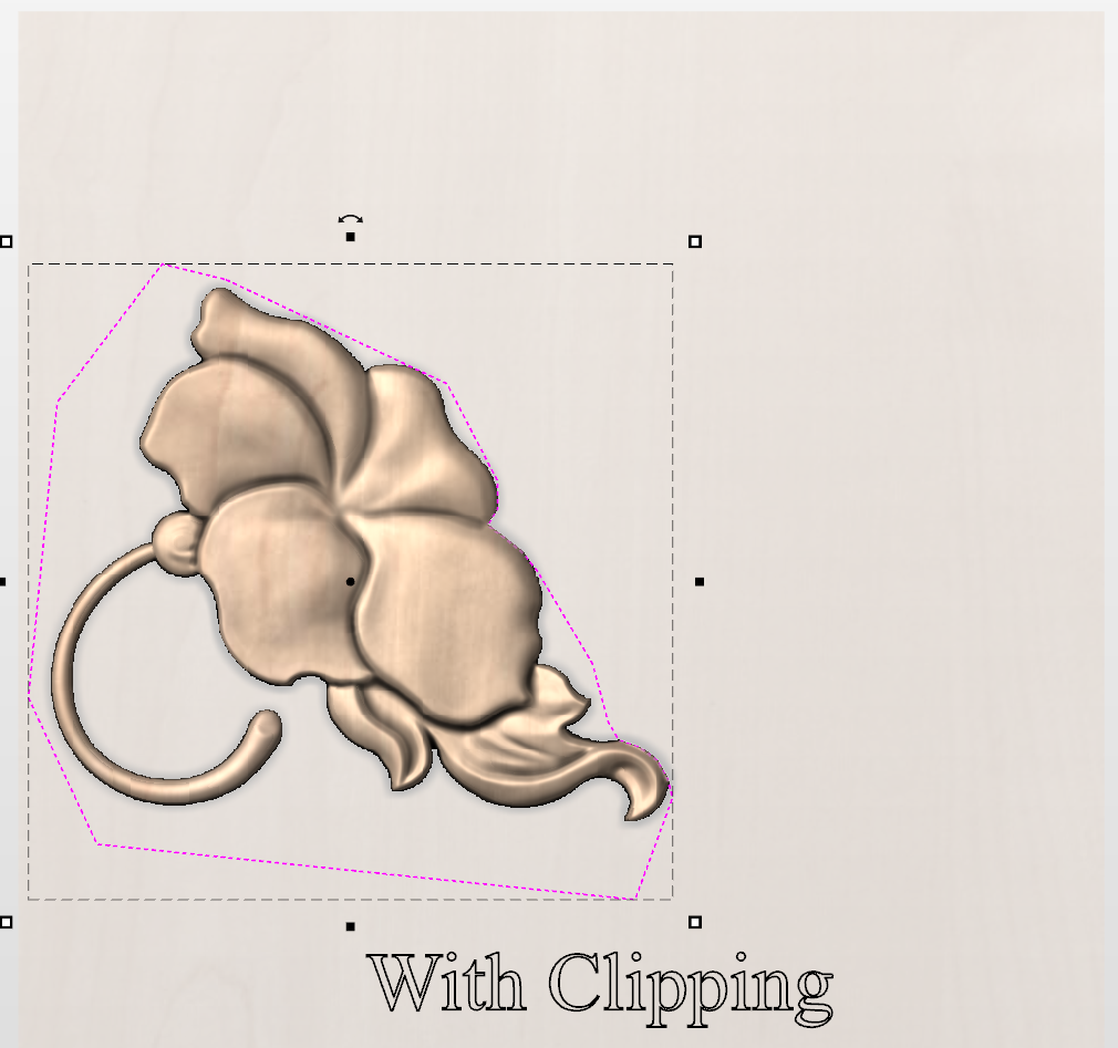
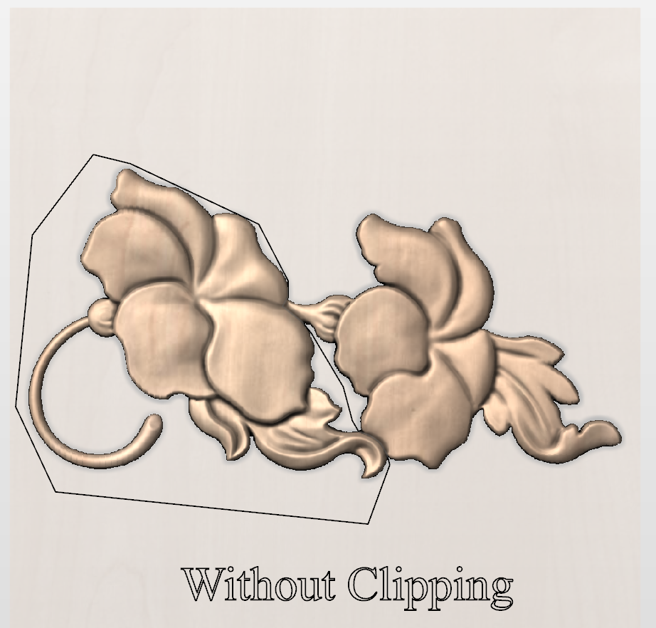
Watch this video to see this in action:
Apply
To apply level clipping vectors, select some vectors and then right click on the level that we want to trim:
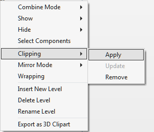
Choose clipping and then apply to clip the level. When this happens then the components on the level are clipped. The areas of the model that lie within these vectors are left untouched, and all areas of the model that lie outside of the vectors are removed.
This clipping is dynamic, so the components on the level can be modified, rearranged, or transferred and the clipping automatically applies to the changed model on the Clipped Level.
Update
Once level clipping has been applied then changes to the underlying clipping vectors do not automatically result in changes to the clipping. To update the clipping boundary:
- Right click on the level and then choose Clipping > Update
- If no vector is selected and the previously used vector is still in the job then the previously used vector will be reused.
- If a different vector is selected then this will now be used as the clipping vector
Remove
To remove the clipping effect from the level, right click on the level and then choose Clipping > Remove.
Draw Rectangle
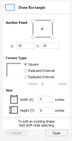
Rectangles can be created by using the Draw Polyline tool or using the Draw Rectangle Tool. The latter tool allows rectangles to be created interactively with the cursor and Quick Keys or by entering the exact coordinates, type of corners (square, internal or external radius) and Width and Height using typed input.
Watch this video to see this in action:
Interactive Creation
The quickest and simplest way to draw a rectangle is:
- Click and drag the left mouse button in the 2D View to begin drawing the rectangle from its first corner.
- While holding the left mouse button, drag to the required size.
- Releasing the left mouse button.
Note
Holding Alt and dragging creates a rectangle from the center. Holding Ctrl creates a square.
Quick Keys
Instead of releasing the left mouse button when you have dragged your shape to the required size, you can also type exact values during the dragging process and set properties precisely.
- Left-click and drag out your shape in the 2D View.
- With the left mouse button still pressed, enter a quick key sequence detailed below.
- Release the left mouse button.
Default
By default, two values separated by a comma, will be used to set width and height of your rectangle. One value will create a square with that side length. While you are dragging out the rectangle corner, type Width Value , Height Value Enter or Side Length , Enter to create a rectangle with the specified width and height.
Example
- 1 , 2 . 5 Enter - Creates a rectangle of width 1 and height 2.5
Specifying Further Properties
By using specific letter keys after your value, you can also indicate precisely which property it relates to.
- Value X - Creates a rectangle at the dragged height but with the width set to the entered value
- Value Y - Creates a rectangle at the dragged width but with the height set to the entered value
- Value R Value X - Create a rectangle with radius R and width X
- Value R Value Y - Create a rectangle with radius R and height Y
- Value W Value H - Create a rectangle with width W and height H
- Value R Value W Value H - Create a rectangle with width W and height H
Examples
- 1 X - Current dragged height with a width of 1
- 1 Y - Current dragged width with a height of 1
- 0 . 1 R 1 X - A corner radius of 0.1, a width of 1 and current dragged height
- 0 . 1 R 1 Y - A corner radius of 0.1, a width of 1 and current dragged height
Note
These key combinations must be pressed whilst dragging with the mouse to create the rectangle.
Exact Size
Rectangles can also be drawn by entering the required XY origin point with the Width and Height of the rectangle.
Corner Type
Corners of the rectangle can be Square, Radiused Externally or Radiused Internally.
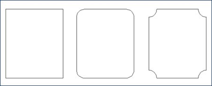
Interactive Corner Radii
If you choose to have radiused corners then 4 additional green handles will appear on the previewed rectangle. These handles can be interactively dragged to modify the radii of the corners.
Editing Existing Rectangles
To edit an existing rectangle:
- Select the rectangle to modify and open the Draw Rectangle form.
- The selected shape is displayed as a dotted magenta line.
- Edit the Width and Height values.
- Click Apply to update the rectangle.
To modify another rectangle without closing the form hold a Shift key down and select the next rectangle.
Usable In Both Views
This tool can be used in both the 2D and 3D View.
2D View offers a more direct way to view your vectors while 3D Offers more flexability to work with Vectors in 3D Designs and to make use of the Edit Boxes.
Clipart Tab
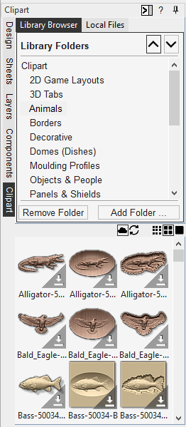
The Clipart tab provides quick and convenient access to V3M files or 2D vector artwork.
This tab includes the library browser that allows you to add folders containing V3M Files into the software or you can use the local files option that allows you to quickly see the contents of several folders of V3M files in one place.
Importing Clipart
To import a file as a piece of clipart you can simply double click its thumbnail to position the clipart in the center of the job. You could also Right click on a piece of clip art and choose the option, this has a sub-menu that allows you to choose an existing Level or to create a New Level. When creating a New Level you will be prompted to enter a name and choose a combine mode. You can also click on a preview image and 'drag and drop' its thumbnail from the clipart browser, into the 2D or 3D View. To do this:
- Move your mouse over thumbnail image in the clipart browser.
- Press and hold down the left mouse button.
- While holding down the left mouse button, move the mouse back into the 2D or 3D View.
- A copy of the thumbnail image will be 'dragged' with the mouse pointer.
- Release the mouse button to 'drop' the clipart file into the 2D or 3D View.
The selected component clipart model or vector outline will be imported at the location of the dropped thumbnail and, if appropriate, added to your model's Component Tree
Library Browser
The library browser provides quicker access to folders on your computer which are in frequent use, or perhaps hold the data for the current project you are working on.
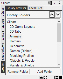
To add a folder into your library click on the button which opens up a dialog asking you to choose the folder you would like to add. Navigate through the tree to choose then folder and click OK. Unlike the Local Files browser the Library browser will only show the clipart that within this folder and folders within this folder. You will not be able to see the whole of the file tree beneath this folder.
Once you have populated your library with folders then clicking on a folder will populate the clipart browser with the objects which are contained in this folder and show you any subfolders immediately below it.
To better understand this, consider the following example: My current project is a western saloon themed sign. I have split up all the resources I am using for this creation into three folders, so that I have the following file folder structure:
Removing Folders
To remove a folder, select from the list of folders and click on the button. This will not delete clipart from your computer; it will just remove the library folder
Adding Folders
Folders may be added to the library from the local file browser by right clicking and selecting the Add folder to library option.
Local Files
The local files browser allows you to select a folder using the file explorer tree in the top section of the page. When you select a folder containing Vectric files (*.crv or *.v3m) the bottom section of the page will fill with thumbnail images of the V3M or CRV files within each folder.
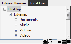
Integrated Windows Explorer Thumbnail Support
V3M files automatically include thumbnails. Windows Explorer can make use of these thumbnails to show you a preview of each file when you browse a folder.
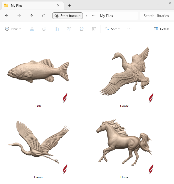
Drag and Drop
Aspire supports Windows drag and drop functionality to quickly add V3Ms into an existing model directly from Windows Explorer.
With Windows Explorer and Aspire both open, simply click and drag the V3M thumbnail of the file you want from the Explorer Window into either the 2D or 3D View window of Aspire. The selected V3M file will be imported automatically and added to the Component Tree
Online and View Controls
Cloud
While this icon is selected and outlined in Blue, this shows the clipart Browser is looking to access Cloud content not yet downloaded to your Local computer.
Clicking this will Show/Hide Online clipart which is not already downloaded to the local computer.
Refresh
Refresh will attempt to login on your Customer Portal account to access available clipart. If you are not signed in, it will trigger you to sign in on your customer portal account.
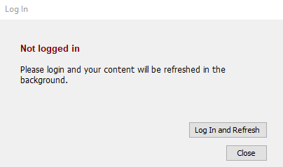
An internet connection is required for login.
This button should be used if you are also having trouble downloading clipart via the Clipart Library to ensure your computer has the latest access to the online library.
View Options
3 Different View options, Left most is smaller Thumbnails, while Right most is the Larger Thumbnails in the Clipart Library.
Replace Below
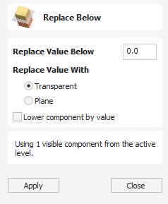
This feature allows you to trim (or flatten) the bottom off a component or multiple components. This could be useful if you've imported an STL model that has some undesired thickness, for example, when it has come from a 3D scan. Also, sometimes you could end up with an undesired negative part of the components (when sculpting, or combining with a deep subtracted model). This tool will allow you to remove anything below a certain height, and (optionally) drop the model by that height.
The result of the operation will be a component that will appear in the Component Tree.
- If only a single component is selected, it will be replaced.
- If multiple components are selected (or a level with more than one component is chosen), they will be baked into a single component, then the operation will applied to the baked component.
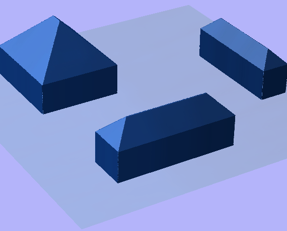
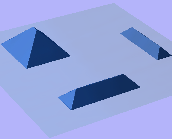
Note
Select one or more components, or use the active level to get started.
Options & Parameters
Replace Value Below
Replace areas that are below the given height with the height chosen by Replace Value With.
Replace Value With
This will control what value to replace those areas with.
- Transparent: Completely remove those areas, and replace them with transparency.
- Plane: Replaces those areas with a plane.The height of the plane is the height input above.
Lower Component by Value
When this option is checked, the model will be dropped by the given height. This is useful if the model is too thick and/or we want to get rid of some background (i.e. one that has come in with an STL model). If you set this to 0, it will remove everything below the Zero-Plane.
Selection
Height Value
The height value is local to the selected component(s). This is equivalent to the value you see if you hide everything but keep the components of interest visible. Therefore, it is easier to apply this to levels.
Level & Component Selection
The effects of this operation are applied to the components and does not necessarily rely on the visible model.To apply this operation:
- Either have one (or more) component(s) selected, or
- Activate a level to select all visible components beneath it.
3D View Selection
To specify a point of the visible model in the 3D view to replace values below; When the form is open, the 3D view will show a moveable plane with a blue central pin. If you click and drag this pin, you can move the plane up or down to a position in which you would like everything lying below it in the model to be replaced.