Tool Database
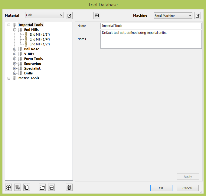
The Tool Database is used to make cutter management and selection very quick and easy, and reduces the possibility of programming jobs with incorrect cut depths and speeds and feeds. It allows pre-defined tools and settings (speeds, feeds, stepover etc.) to be selected from a list for a given machine / material.
The Tool Database can be accessed from the button through the various Toolpath forms. You can open the Toolpaths Tab button or through the Toolpaths menu.
Overview
This is a summary of the main entities and relationships in the database. More details on those will be given in the next sections.
- Tool geometry entities (organised hierarchically in the tree).
- List of Materials (Managed through the Material Management dialog).
- List of Machines (Managed through the Machine Management dialog).
- Cutting Data set for each tool geometry. This includes the Cutting Parameters, and Feeds & Speeds, and are defined per machine / material.
Tool Properties are divided into two categories,
- Tool geometry: This is the physical properties of the tool such as the diameter, tip radius, etc...
- Cutting data: These include the Cutting Parameters and Feeds & Speeds of the tool. These values are defined for a particular material / machine.
Apply Changes
If you modify the Tool database, your changes will only be saved if you click OK. If you exit the Tool Database window using the Cancel button, any changes you have made since opening the Database will be discarded.
Tool Tree
The Tool Tree is located on the left-hand side of the Tool Database. Click on items in the list to see or edit their properties using the Tool Info section of the database window.
You can drag items up and down the list to change their order or drag them inside / outside of groups.
New Tool
Create a new tool with the default name for its type. The tool will be created with the first available type by default, but that can be changed through the Tool Type dropdown to the desired type.
Copy Tool
Duplicate the selected tool geometry or group in the list. If you're copying a tool, it will be copied without its cutting parameters.
The cutting parameters can be subsequently be:
- Copied from the same tool, different material.
- Tool with identical geometry, any material.
- Created with default values.
Delete Tool
Delete the tool as well as all of the cutting data for all machines / materials for which it was defined. If we're deleting a group, this will delete all the tools inside it in the same way.
New Tool Group
Create a new group in the tool database. Tools can then be dragged inside the newly created group. Alternatively, select the group and create a new tool directly under the selected group.
Export Tools
Export an individual tool or an entire group to a tool database file.
Import Tools
A tool database file can be imported into the currently open tool database. You will have 3 options,
- Import: This will simply import the given tools under the selected group (or as a top-level tool / group).
- Merge: This will attempt to merge the incoming tool group hierarchy with the current one (without any regards for selection)
- Overwrite: When it's faced with two similarly nested tools that have the same tool geometry, the cutting data of the incoming tool will overwrite the current tool's cutting data for the active machine / material.
- Without overwriting: A new machine / material will be created to contain the cutting data of the incoming tools.
Tool Definition
When a tool or group is selected in the Tool List, its properties are displayed in the Tool Info section on the right-hand side of the Tool Database.
Name
This will go to the Name Format dialog to edit the name template for this tool type.
The name displayed here is then a result of evaluating the template in the current context (active machine, material and the cutting data defined for those as well as the tool geometry).
The name of a tool group can be defined directly through this dialog.
Tool Type
Various cutters can be specified in the database. Changing the cutter tool type is equivalent to creating a new tool, so all existing data for that tool (if any) may not be applicable anymore.
Notes
The tool notes section simply allows you to save any additional text descriptions, special instructions or relevant information you may require, within your tool definition.
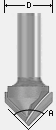
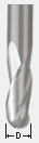
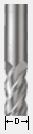
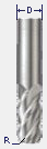
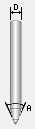
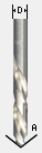
Diameter
The diameter of the tool in either inches or mm. The tool image will indicate where this dimension is taken from.
Number of Flutes
The number of Flutes for the bit. This is particularly useful if you would like to calculate a Chip Load value.
Cutting Data
The cutting data is the set of parameters which can differ between materials and machines. This set of parameters are defined to be per machine per material. The visible set of parameters are the ones for the active material / machine.
Creation / Copying
The cutting data is defined per material per machine. If the data is not defined already for a tool, we create it in a number of ways,
- Create with some default values which you can then change for your purposes.
- Copy from the same tool from a different material: This could be a sensible starting point if the materials have similar / close hardness.
- Copy from a different (identical) tool from the same (or different material)
Pass Depth
The maximum depth of cut the tool can cut. The Pass Depth controls the number of z level passes that are calculated for a toolpath.
For example, creating a pocket 1 inch (25.4 mm) deep using a tool that has a Pass Depth of 0.25 inches (6.35 mm) will result in the toolpath making 4 passes.
This value can be defined per machine / material depending on the machine's rigidity and the material's hardness.
Stepover
The distance the cutter moves over when doing area clearance cutting. For example, when raster machining the cutter will machine along the X axis, stepover in the Y direction and return parallel to the first line of cut. The greater the stepover the faster the job will be machined, but this must be balanced with the material being cut and the tooling being used, to ensure that the tool does not break. Therefore, this property (along with all other Cutting Parameters can be defined per material / machine).
When stepover's greater than 50% of the cutter / tip diameter are used the software automatically adds 'Tail' moves in the corner regions of toolpaths to ensure material is not left on the job for offset based strategies.
When using V-Bit Tools, the Stepover fields automatically change to use the following options.
Final Pass Stepover
The distance the cutter moves over when finish machining and is usually set to be a relatively small distance to produce a smooth surface finish on the job.
Clearance Pass Stepover
Only used when a V-Bit tool is being used to rough machine at multiple Z levels down to a specified flat depth. This stepover can be much larger than the Final Pass Stepover because the tool is only rough machining material away. Increasing the Clearance Pass Stepover will reduce the machining time, but you must be careful to ensure it is not too great for the material being cut.
Spindle Speed
Speed of tool rotation, specified in revolutions per minute.
Feed Rate
The surface cutting rate at which the cutter is moved in the material. The units can be specified in distance per second or minute.
Plunge Rate
The cutting rate at which the cutter is moved vertically into the material or during ramping moves. The units can be specified in distance per second or per minute.
Material / Machine
The Feed rate and Plunge rate you should use will vary depending upon the material being machined and the tooling being used.
Chip Load
This is the calculated Chip Load based on the entered values for the Number of Flutes, Spindle Speed and Feed Rate. This is displayed to conveniently be able to compare it with manufacturer-recommended Chip Load Values.
Maximum Burn Rate
This is the maximum speed at which the tool, when at 100% power, will still burn the material. This value is used for simulation purposes only. It should be calibrated to match your laser and material. A larger value will result in the simulated toolpath appearing darker.
You will need access to the Laser Module to create and simulate laser toolpaths.
Tool Number
This is the number of the tool needed to machine the job. When using a CNC machine with an Automatic Tool Changer (ATC), it is critical that the correct tool required to cut the job is located in the corresponding carousel location.
Per Machine
This parameter only needs to be defined per machine and so is shared between materials (unlike other cutting data parameters which are defined per machine per material).
Material / Machine Management
The cutting parameters / feeds & speeds section of the tool properties is defined for the active machine / material. This allows you to setup your tools with different values for each material or machine and switch between easily depending on the material you're going to use for the current job.
Material
The combo box is used to change active material. This can also be done by going to the Material Management dialog where materials can be added, removed or edited.
Machine
The combo box is used to change active machine. This can also be done by going to the Machine Management dialog where machines can be added, removed or edited.
Online Tool Database
The tool database can be stored and linked to your portal account so that it can be retrieved at any point from a different installation. For this, the software needs to be logged in to the portal account. Then, the database can be uploaded / download on request.
Login
Login to the portal to be able to access the currently stored tool database and / or upload your existing local one.
Download
Download the tool database stored on your portal account to replace your existing local tool database. This can be used for when we know there is a more up-to-date version online.
Upload
When changes have been made to the tool database, this will upload it to the portal account so that it can be downloaded from any other location linked to the same portal account.
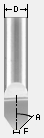
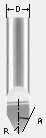
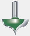
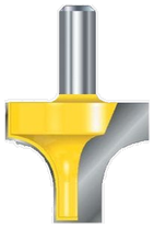
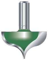
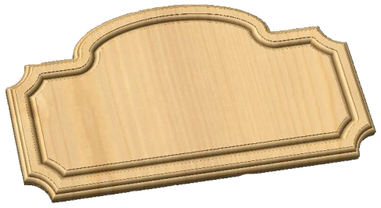
Using Form Cutters
Form Cutters can be added to the Tool Database so that industry standard Ogee and Round-over type cutters, plus user definable custom shapes can be used for edge profiling and decorative carving.
Examples of these types of cutters and the kind of cuts they can be used for are shown in the images below:
Custom Form Cutters
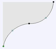
Before opening the tool database, draw to exact scale the Right side of the cutter geometry in the 2D Window Use the Node Editing tools to create the arcs and curves etc.
Geometry
Only draw the Right-hand side of the cutter geometry to the correct size and scale as shown in the image above. The shape can be a combination of Lines, Arcs and Bezier spans.
Select the vector, then open the Tool Database dialog and create a new tool. Then, set its type to Form Tool.
The selected geometry will be imported and a profile displayed in the window. Give the Cutter a meaningful name. Enter the cutting parameters - speeds and feeds etc for the various materials you've got defined.
Click the Apply / OK button to save the new cutter into the database list so it can be used at any time.