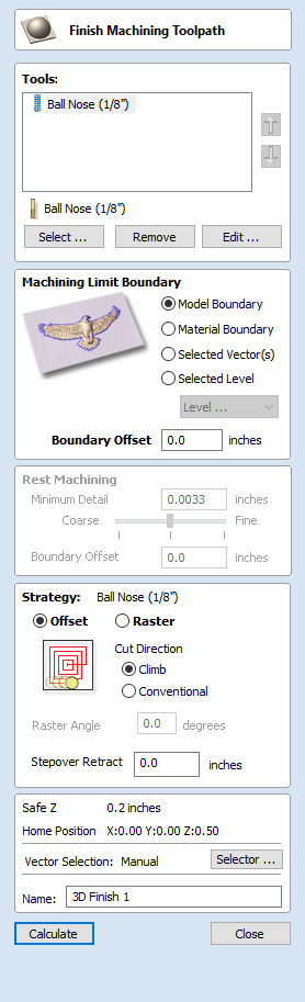
3D Finish Toolpath
Finish Machining is used to machine the final pass on the finished 3D part.
For most 3D Finishing cuts a Ball Nosed end mill is used with a reasonably small stepover (8 - 12% of the tool diameter is typical). Variations on this tool type such as a tapered Ball Nosed cutter will also work and may offer more strength with smaller tool sizes. The size of tool will depend on the size of the part and the detail within the 3D part. Use the preview function to check the finish quality and detail; if they are not to a high enough standard then the job may require smaller tooling or a smaller stepover. 3D cutting is always a tradeoff between time and quality and an optimum balance of tool size, finish quality, and time to cut. The choices made will always depend on an individual's personal preferences or the specifications of the job.
Note
The finishing toolpath is always a single pass, and it does not use the tool's pass depth. Please ensure that your Roughing Toolpath's Machining Allowance is set appropriately for the tool used in Finishing to avoid damaging the bit.
 Tool Selection
You can select any number of tools you wish to use to create this toolpath. When multiple tools are chosen then the first tool removes as much material as it can, all subsequent tools in the list will remove as much material as it can from any previously unmachined areas. If multiple tools are selected then the order of the tools in the list should match the order they will run on the machine.
Note
Sometimes an allowance will be left on for the final tool to remove.
Clicking the button opens the Tool Database from which the required clearance tool can be selected and added to the list.
Clicking the button will remove the selected tool from the list.
Clicking the button opens the Edit Tool form which allows the cutting parameters for the selected tool to be modified, without changing the master information in the database.
Clicking the up and down arrow buttons will move the selected tool up and down the list respectively.
Machining Limit Boundary
The machining limit boundary is the area in which the tool will operate. There are several options:
Model Boundary The combined boundaries of all the components in this job are used. This is the area of the composite model which has components on it. Note: this is not the boundary of the selected models.
Material Boundary The boundary of the entire material block is used.
Selected Vector(s) Selected vectors are used as the machining boundary.
Selected Level The combined boundaries of all the components on the specified level. This is similar to Model Boundary, but only specific to the named level.
Boundary Offset
If you are machining a raised object, often the tool will not fully machine down the edge. This field is used to specify an offset to the selected machining boundary to increase its size to allow the tool to go past the actual edge if needed.
Area Machining Strategy
There are two choices of the type of fill pattern that will be used to machine the area with the toolpath; Offset and Raster.
Offset

Your choice of Climb or Conventional cutting will largely be dictated by the material that is being machined and you're tooling options. Talk to your tooling suppliers for details about what is most appropriate for your specific application.
Raster

Calculates a raster pattern (lace cut) projected onto the 3D surface and machined inside the selected vector(s), with control over Raster Angle - Between 0 and 90°. 0° will give you a pattern that is mainly parallel to the X axis and 90° is mainly parallel to the Y axis.
Stepover Retract
The Stepover Retract Value can be applied to the Offset Machine Strategy. If the value you enter is greater than 0 then the tool will lift off the surface of the composite model by this amount when stepping between each offset contour. Depending on your material and tooling, adding a small lift will eliminate perpendicular tool marks between the toolpath contours to potentially improve the finished surface.
Note:
If the Stepover Retract Value specified is not large enough to allow the machine to lift the tool over the previous cusp height then you will receive a warning. This warning is simply informing you that with a Stepover Retract value of this size then you will not eliminate perpendicular tool marks.
Rest Machining
Rest machining is a technique which uses multiple tools to try and optimize for machining time, material removal and tool lifetime. A series of tools can be chosen, with each tool removing any remaining material that the previous tool was unable to machine. If multiple tools are selected then rest machining will be used.
Minimum Detail
The minimum detail value and corresponding slider controls how small an unmachined area should be if it is going to be ignored by this particular tool in the toolpath. The result of finish maching with one tool will always leave areas of the model that are not completely machined. Often these unmachined areas are so small that it is not desirable to have a smaller tool to try and machine them. For example, it is unlikely that we would want to have the smaller tool try to remove the unmachined cusps of a previously cut toolpath.
Setting the minimum detail is likely to be a compromise between achieiving greater detail versus reducing machining time.
Boundary Offset
The boundary offset value specifies a value that every unmachined area will be offset by. A low value for the boundary offset will result in this tool machining lots of smaller areas. A high value will result in this tool machining fewer but larger areas.
Position and Selection Properties
Safe Z
The height above the job at which it is safe to move the cutter at rapid / max feed rate. This dimension can be changed by opening the Material Setup form.
Home Position
Position from and to that the tool will travel before and after machining. This dimension can be changed by opening the Material Setup form.
Vector Selection
This area of the toolpath page allows you to automatically select vectors to machine using the vector's properties or position. It is also the method by which you can create Toolpath Templates to re-use your toolpath settings on similar projects in the future. For more information, see the sections Vector Selector and Advanced Toolpath Templates.
Name
The name of the toolpath can be entered or the default name can be used.