Right Mouse Click Menu
Clicking the ►RIGHT hand mouse button in different places in Aspire will display a menu with choices which depend on the area of the software being clicked on and/or the object or selection that the mouse cursor is positioned over. This page details some of these areas and the menus that you will see when RIGHT mouse clicking.
 2D View
This menu is displayed when you Right mouse click in 2D View either in the white background of the part or over a selected vector. Most of these options repeat functions and icons described elsewhere in this manual, you should refer to the appropriate section to view how these work.
Layer and Side Operations
The Copy to Layer, Move to Layer, Move to Sheet, Copy to other Side, and Move to other Side options are unique to this Right click menu.
- Copy to Layer allows you to copy an object onto an existing Layer or to create a New one to copy it onto.
- Move to Layer gives you the same choices but moves the original object rather than making a copy.
- Move to Sheet can only be used if you have generated additional Sheets through the Nesting process, in that case it allows you to move objects from one Sheet to a different one from the list available.
- Copy to Other Side copies the selected objects onto the other side in a two-sided job. The objects will be transformed so that they match up when looking through the material.
- Move to Other Side moves the selection similarly to the Copy operation.
Span Editing Menu
If the current selection mode is set to Node Editing, one of two different menus will appear when the user clicks the RIGHT mouse button depending on whether the cursor is currently over a vector Node or a Span of a selected vector in the 2D View. These menus have functions in them that correspond specifically to this selection and position. The menu shown here will appear when the cursor is over a Span of a vector in Node editing mode. You can see a variety of choices: to convert the span to a Line, Bezier (curve) or Arc, Insert a Point, Cut the Vector at that point, Delete the Span, or Insert a Midpoint. Keep Bezier Tangency, which will fix the start and end directions of Bezier curves when they are being dragged directly, can be toggled on or off. From this menu you can also Reverse the direction of the selected vectors, Close any selected open vectors, Join two selected open vectors or Exit node editing mode. Many of these have corresponding Shortcut keys (shown to the right of the command in the menu) which can be selected from the keyboard when the mouse is in position (over a node-edit vector span) instead of Right Clicking the mouse button to access the menu.
Node Editing Menu
This menu will appear when the cursor is over a Node of a vector in Node editing mode. You can see a variety of choices: Delete the Point, Smooth it, Insert a point at a virtual midpoint, Cut the vector at that point, change the point to be the Start Point of the vector or extend the vector using the Polyline tool. Horizontal or vertical mirror mode for node editing can be toggled on or off. From this menu you can also close any selected open vectors, Join two selected open vectors, Exit node editing mode or lastly see and edit the exact XY co-ordinate position of the node by selecting Properties. Many of these have corresponding Shortcut keys (shown to the right of the command in the menu) which can be selected from the keyboard when the mouse is in position (over a node-edit vector node) instead of Right Clicking the mouse button to access the menu.
Bitmap Properties Dialog
When a Bitmap or Component Grayscale is the selected item in the 2D View and the RIGHT Mouse menu is activated then there will be an additional option in the pop-up menu called Object Properties. This will open the dialog shown below which can be used to fade the Bitmap or Grayscale object strengthen or fade the detail in it when it is not selected. This can be helpful to make it easier to see features perhaps to help you manually trace vectors over it or to fade them so its easier to see vectors that overlap the object.
Level Menu
When a Level in the Component Tree is selected and you RIGHT mouse click on it then the menu shown below will appear.
The first section allows you to make alterations to the selected level where you can change how the level combines with levels below it, you can choose to show or hide the level's visibility (and consequently the Components on it). Using the Select components option will select all the components within the level.
The next section contains the level effects which apply an effect to the level without affecting the individual components.
- The Clipping effect will dynamically clip the combined components on the level to the closed vectors which were selected when the effect was checked on.
- Mirror Mode allows you to mirror the combined components on the level in various ways.
- Wrapping is available for rotary jobs only and will allow components outside the job area that would otherwise be truncated to wrap around to the other side.
The next section allows you to insert new levels, delete the level and rename the selected level.
The final section of the menu allows you to export the complete contents of the level as a .3dClip file - when re-imported this would come into Aspire as a group.
Component Menu
This menu appears when a Component is selected in the Component Tree and you RIGHT mouse click on it:
The first option allows you to select the way the component combines with the other objects on its Level. You then have the option to position the components grayscale in the 2D View, by moving that to the Front or the Back. You then have the options to Copy and duplicate a component along with the option to Export the selected component as a .3dClip file. If you have more that one component selected you have the option to Group/Ungroup the components. You can delete and rename a component. There is also the option to show components, where you can choose to Show This, Show Only This, Show All But This and Show All. You can Hide a component, where an extra menu allows you to Hide This or Hide All. You can open the properties form for the selected component and the last option allows you to move the component to a new or existing Level within the Component Tree.
Component Grayscale Menu
When a Component Grayscale is the selected item and Object Properties is selected it opens the Bitmap Properties slider, allowing you to change the fading of the grayscale component. Two other options are also available on the Right mouse click menu for a selected Component Grayscale. Move to Front and Move to Back. Clicking Move to Front will make the selected Grayscale appear over all the other Grayscales on the same layer so you can see the selected one more easily. Move to Back will send the selected one behind all the others on the same layer so that it is easier to see all the other Grayscales in the part.
3D View Menu - Selected Component
When a component(s) is selected in the 3D view you can RIGHT mouse click and make changes to that selected component(s). You can check the combine mode of a component. You can Unselect a single component or Unselect All depending on how many components you have currently selected. You can hide and delete a component. You can open up the properties form for that component and you have the option to move the selected component(s) to an existing or new Level.
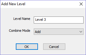
If you choose New Level you will be presented with the box below, where you simply add in the name for the new level and choose a combine mode from the dropdown menu.
3D View Menu - Non-Selected Components
When you RIGHT click on a component without selecting it first the menu will display the names of the components that are positioned at the point your cursor is within the job space. Selecting the name of the component will select it and open up the Properties form for that selected component.
Clipart Menu
When you RIGHT click on a piece of clipart in the clipart tab you have the option to import it to a new or existing level in your job. This will position the object in the center of the workspace and add it to the top of the list of Components on the selected Level or if you choose New Level will allow you to enter a name and Combine Mode.
Toolpath List Menu
When you RIGHT click on a toolpath name within the Toolpath List there are various options you are presented with to alter this toolpath. You can show a toolpath where you have the option to
- Show This,
- Show Only This,
- Show All But This
- Show All With This Tool
- Show All.
This toggles the visibility of the Toolpaths according to your choice. The next option allows you to Hide This or Hide All your toolpaths. Activate Sheet will make the sheet associated with the selected toolpath the active one.
You can Edit, Rename or Duplicate the selected toolpath. The Recalculate submenu allows you to recalculate the selected toolpath, visible toolpaths or all toolpaths with any updated geometry selections.
Create an Empty Group will create an empty toolpath group which you can later place toolpaths inside. Group Visible will create a toolpath group containing the visible toolpaths.
Ungroup allows you to remove a toolpath group while preserving the toolpaths it contains. The Delete submenu allows you to delete one or more toolpaths, where you can Delete This, Delete All Invisible, Delete All Visible and Delete All.