Chamfer Toolpath
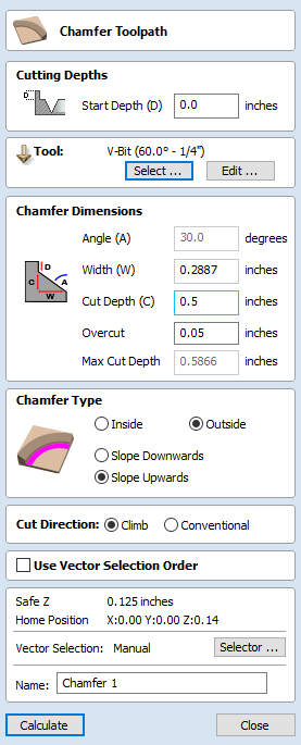
The Chamfer Toolpath uses the selected vectors and tool to create an angled feature
The Chamfer Toolpath has two distinct ways of operating depending on the tool used:
- If the selected tool is an angled tool, then the angle of the tool determines the angle of the chamfer
- If the selected tool is a round nosed tool, then the angle of the chamfer must be specified manually, and will be approximated by a series of fine cuts.
Cutting Depths
The Start Depth (D) specifies the depth at which the top of the chamfer should start.
Vector Selection
To create the toolpath you must first draw and then select the vectors you wish to create the chamfer on.
Tool
Clicking the button opens the Tool Database from which the required tool can be selected. See the section on the Tool Database for more information on this. Clicking the button opens the Edit Tool form which allows the cutting parameters for the selected tool to be modified, without changing the master information in the database. Hovering the mouse cursor over the tool name will display a tool tip indicating where in the Tool Database the tool was selected from.
Chamfer Dimensions
The chamfer dimensions control the shape of the created chamfer.
Angle (A)
The angle determines the slope of the chamfer. It is measured from vertical.
When a V-Bit tool is selected for the toolpath then the angle is fixed to half of the angle of the tool.
For a round nosed tool then the angle may be specified.
Width (W)
The width determines the horizontal size of the chamfer. If the angle is set then changing the width will change the cut depth proportionally.
Cut Depth (C)
The Cut depth is the height of the chamfer. If angle is set then changing the cut depth will change the width proportionally.
Max Cut Depth
To achieve the desired height of the chamfer, as specified by the cut depth field, cutting deeper might be required. This will be true in the case of a round-nosed tool.
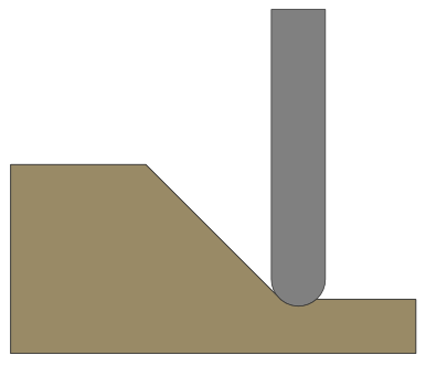
The Max Cut Depth field is read only and shows the full length of the cut so you can accurately see how deep the tool cuts.
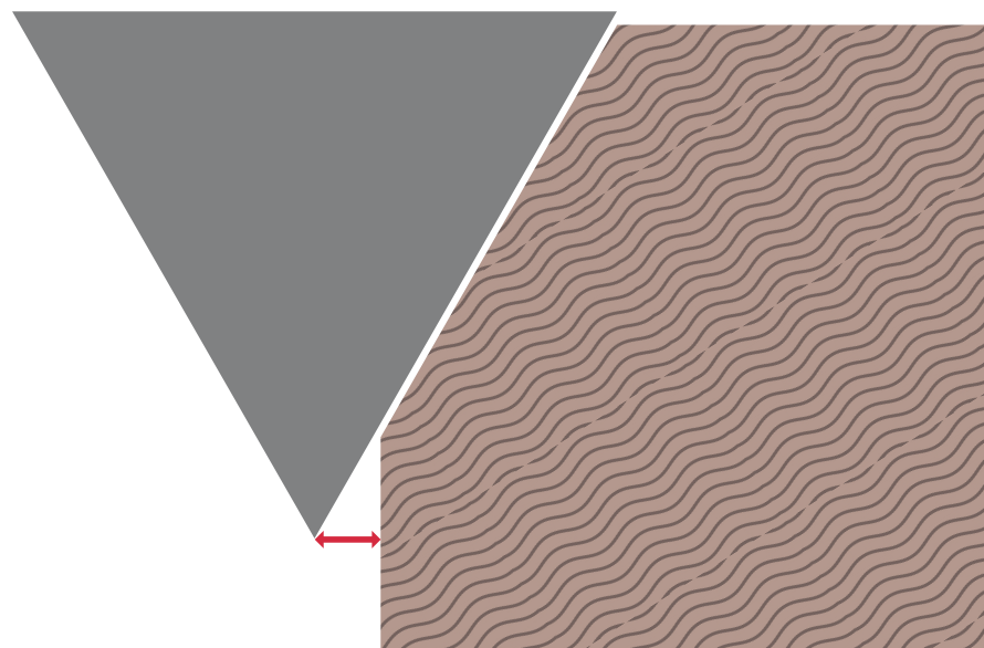
Overcut
When using a V-Bit tool for chamfering it can be desirable to use the edge of tool, and keep the point of the tool off the part. Small movements in the machine and the material can mean that the point of the leaves an unsightly witness mark. The overcut control allows you to specify a value that will be used to offset the centre of the tool, and use the side of the tool for machining.
Note
The length of the side of the tool is unknown and so when specifying an overcut distance you should always ensure that the cutting edge of the tool is long enough to accomodate the overcut distance.
Chamfer Type
The Chamfer Type option controls whether or not a chamfer occurs inside or outside a vector and the direction of the chamfer slope :
- An inner chamfer will be inside the selected vector.
- An outside chamfer will be outside the selected vector.
The direction of the slope tells us whether our chamfer is upward or downward relative to the selected vector or whether it is downward relative to the selected vector.
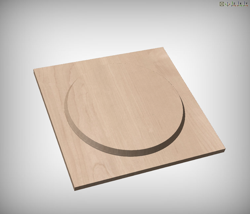
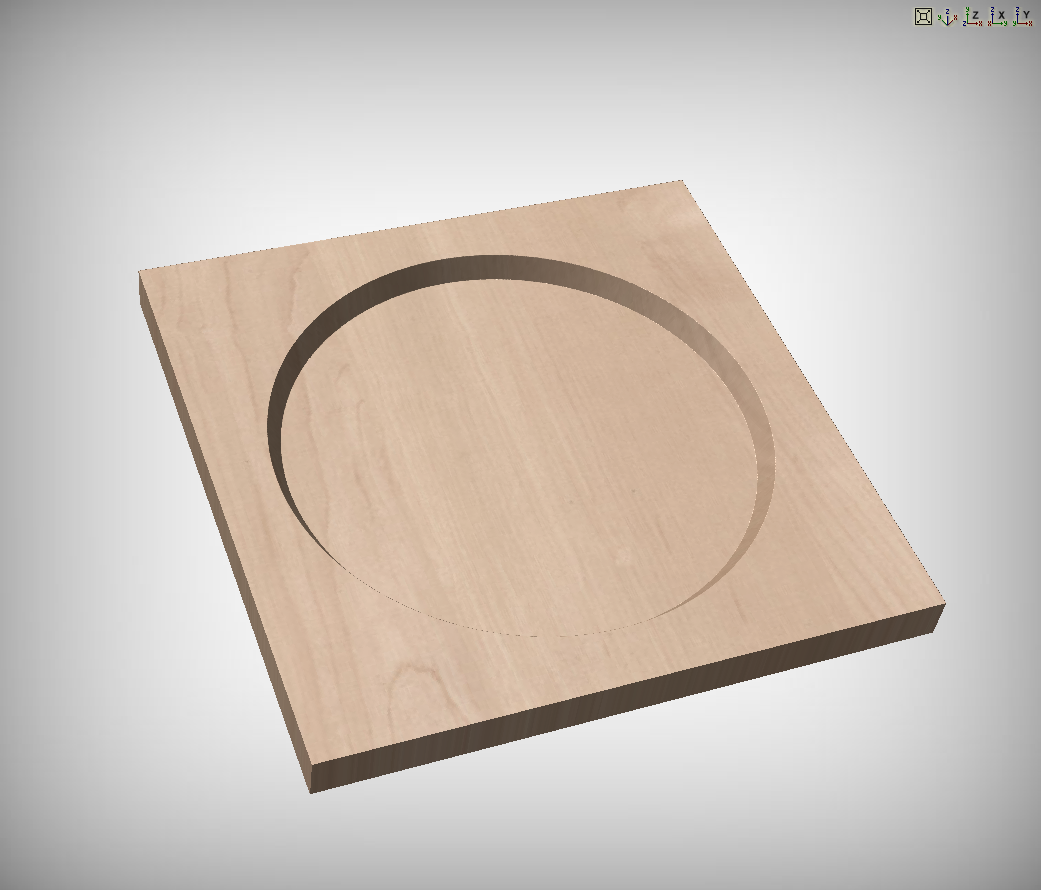
Both options can be used together to generate different chamfer styles.
Cut Direction
The cut direction may be set to either climb or conventional milling.
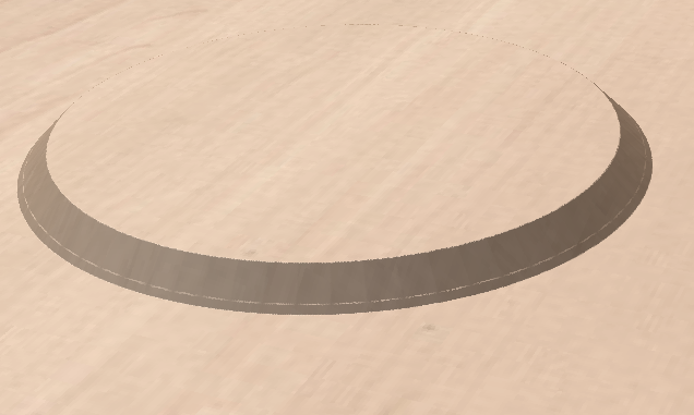
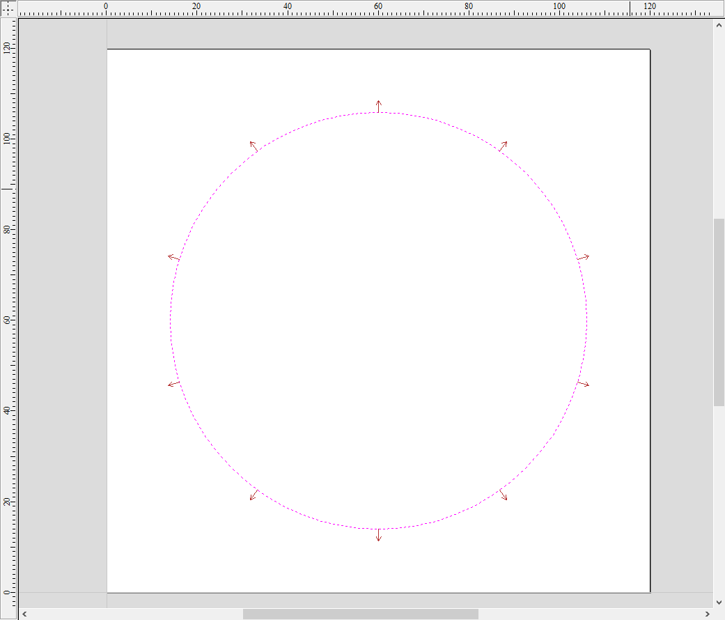
2D Preview
When using the Chamfer toolpath the 2D View will provide immeditate feedback on what the resulting chamfer will look like. Small lines will extend outwards from the selected vector to show where the slope of the chamfer will lie. The arrows on these line indicate the direction of slope. The arrows always point down in the direction of the downwards slope.
Use Vector Selection Order
If this option is checked, ✓ the vectors will be machined in the order you selected them. If the option is not checked the program will optimize the order to reduce machining time.
Position and Selection Properties
Safe Z
The height above the job at which it is safe to move the cutter at rapid / max feed rate. This dimension can be changed by opening the Material Setup form.
Home Position
Position from and to that the tool will travel before and after machining. This dimension can be changed by opening the Material Setup form.
Vector Selection
This area of the toolpath page allows you to automatically select vectors to machine using the vector's properties or position. It is also the method by which you can create Toolpath Templates to re-use your toolpath settings on similar projects in the future. For more information, see the sections Vector Selector and Advanced Toolpath Templates.
Name
The name of the toolpath can be entered or the default name can be used.