Thread Milling Toolpath
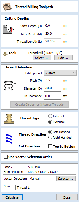
The Thread Milling Toolpath produces:
- internal thread, i.e., something you can screw a threaded bolt into.
- external threads, i.e., the threads for the exterior of a bolt.
It does this by using a special physical tool and a helical toolpath.
To use the toolpath select the vectors you wish to create threaded parts for. The center's of these vectors will be used to define the center of the threaded part.
Set the parameters to match the thread type you require, and then hit calculate to create the toolpath.
Tool Selection
Clicking the Select button opens the Tool Database from which the required Tool can be selected.
Clicking the Edit button opens the Edit Tool form which allows the cutting parameters for the selected tool to be modified, without changing the master information in the database.
The thread milling toolpath supports two types of tool:
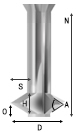
Single Point Tools
When using a single point tool then the created toolpath form a helix. The cutter at the side removes stock material to form the thread.
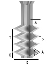
As seen in the above diagram, a single pointed thread mill tool is assumed to have a triangular cutting face. This triangle is the part of the tool that stands out from the shank of the tool and removes material:
The definition of the tool requires the following fields:
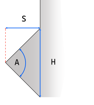
- S - The Tool Size. The horizontal size of the cutting part of the tool
- H - Tool Height. This is the vertical height of the widest part of the cutter face
- D - Tool Diameter. The diameter of the cutter measured from tip to tip.
- A - Tool Angle. The internal angle of the tool
- O - Tool Offset. This is the distance between the bottom of the tool and the tip of the cutter. It must always be bigger than the half of the tool size. Some tools may also have an additional offset, so it may exceed this value.
The Tool Height, Tool Size, and Tool Angle are all related fields. Changing one may change another. For example, if you modify the Tool Height, and the Tool Angle does not change, then the Tool Size must change. This change happens automatically when editing the tools within the tool databse.
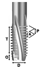
Multi Point Tools
It is possible to use a multi-pointed tool for thread milling. A multi-pointed has been designed to cut a single style of thread using a single helical motion. It will cut all the threads in a single go making it more efficient. However unlike single point tools it cannot cut different threads of different pitches.
In addition to the dimensions required for the single pointed tool, the multi-point tool also needs to know the threaded length. This is defined as the distance from peak to peak from the first cutting tooth to the last.
Advantages and Disadvantages
- Single point tools have more flexibility when it comes to the threads that they can cut. The cutting paths can compress or extend to create threads with different pitches.
- Single point tools will be slower. They must machine all the threads with the one cutting edge, so will be many times slower than the equivalent multi-threaded tool.
- For large wood-working style jobs then it is unlikely that you will find multi-threaded tools of the right size.
- For cutting standard sized threads then a multi-threaded tool will be correctly spaced and easy to use.
- In the software, with a multi-point tool you cannot alter the pitch, and the toolpaths thread length must be at most the thread length of the tool.
Thread Definition
Pitch Preset
You can choose from one of a number of standard presets for the pitch. The standards are based on the ISO Metric Thread Standard for metric units, or the Universal Thread Standard for imperial units.
Selecting one of these options will pre-populate the pitch field with the correct value. If an external thread is selected it will also populate the fit tolerance field with a default value appropriate for the pitch. You are free to change this tolerance, however some tolerance will usually be required to have a smooth spinning thread.
Pitch
The Pitch describes the difference between the ridges of the thread.
Diameter
Each thread has two diameters associated with it. These are the respective peaks and troughs of the thread.
The diameter on the form (sometimes referred to as the major diameter) is the largest diameter associated with the thread.
Fit Tolerance
The fit tolerance controls how tight a fit the thread will have. Setting a positive tolerance will mean the tool cuts a slightly deeper thread.
In almost all practical uses, some form of fit tolerance would need to be applied in order to get a thread to run smoothly. Generally the fit tolerance is applied to the external thread but can be applied to both internal and external if needed.
Create Circles for Internal Threads
When cutting an internal thread you may have an area inside that thread that needs to be removed with another tool. Calculating what area can be safely removed can be a little bit of work, so to make that easier the button will create a circle that the user can apply a Pocket toolpath to, to clear this region.
Thread Type
There are two different types of thread it is possible to create:
- Internal Threads - These are threads for the female parts of connectors, e.g., nuts, threaded holes.
- External Threads - These are the threads for the male parts of connectors ,e.g. bolts.
Direction
Thread Direction
A thread can be either right-handed or left-handed. This determines the clockwise/anti-clockwise direction of the thread as it spirals.
Cut Direction
The cut direction determines whether or not we want to machine the toolpath by sprialling downwards or upwards.
Which direction you choose will depend in some part on the relationship between the spindle direction, the tooling, and the desired finish.
Created Threads
The threads created by the Thread Milling toolpath are based around the ISO standard for threads. More information about this standard can be found here. This is based on tools with 60 degree angles and whilst we do not prevent other angles of tools from being used a 60 degree tool would give optimal results.
The result of using this standard is that the created threads will have flat regions as expected:
Use Vector Selection Order
If this option is checked, ✓ the vectors will be machined in the order you selected them. If the option is not checked the program will optimize the order to reduce machining time.
Position and Selection Properties
Safe Z
The height above the job at which it is safe to move the cutter at rapid / max feed rate. This dimension can be changed by opening the Material Setup form.
Home Position
Position from and to that the tool will travel before and after machining. This dimension can be changed by opening the Material Setup form.
Vector Selection
This area of the toolpath page allows you to automatically select vectors to machine using the vector's properties or position. It is also the method by which you can create Toolpath Templates to re-use your toolpath settings on similar projects in the future. For more information, see the sections Vector Selector and Advanced Toolpath Templates.
Name
The name of the toolpath can be entered or the default name can be used.