SketchUp Files
SketchUp files with a .SKP extension (see www.sketchup.com) can be imported as 2D data suitable for machining into a VCarve Pro job using the File ► Import Vectors... command from the menu bar or the import vectors icon on the Drawing tab. To import data from a SketchUp file you must already have created or opened a job to import the data into.
As a SketchUp model is usually a 3D representation of the part, the SketchUp importer offers a number of options to allow you to start manufacturing the model.
We will illustrate the two main choices for how the model will be imported using the SketchUp model shown to the left.
The model shown in the screenshots is a cabinet constructed by following the instructions in the Fine Woodworking 'Google SketchUp guide for Woodworkers: The Basics' DVD which is available via the Fine Woodworking site at www.finewoodworking.com. Vectric have no affiliation with Fine Woodworking, we are just using screenshots of the model constructed while following their tutorials to illustrate the process of importing a SketchUp model.
Layout of Imported Data
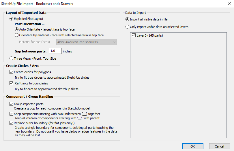
In the first section there are two main choices for how the data from the model will be imported, 'Exploded Flat Layout' and 'Three Views - Front, Top, Side' as shown below.
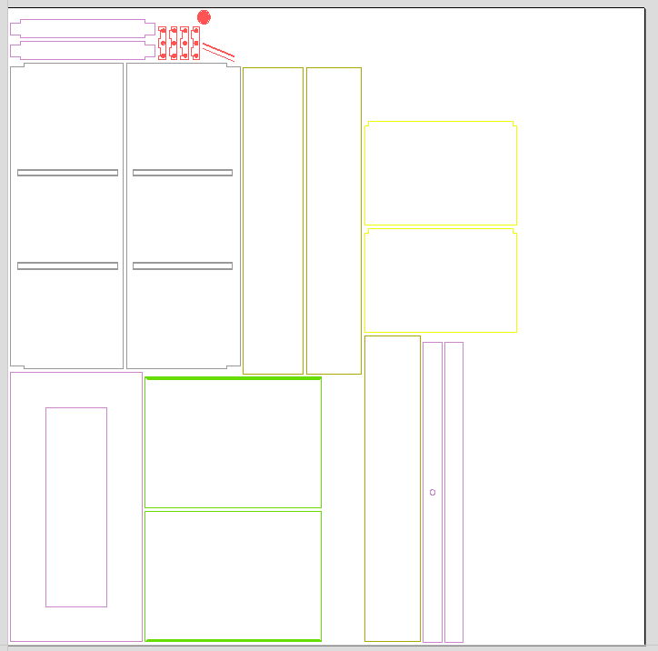
Exploded Flat Layout
This option will take each component in the model and orientate it flat ready for machining.
Once this option is selected a number of sub-options also become available.
Part Orientation
This section controls what Aspire considers to be the 'top' face of each part.
Auto Orientate
If this option is selected, for each part in the model, the 'face' with the largest area based on its outer perimeter (i.e. ignoring holes etc.) is considered to be the 'top' face and the part is automatically rotated so that this face is facing upwards in Z. This strategy works very well for models which are to be manufactured from sheet goods where there are no features on particular faces which need to be on the 'top' (such as pockets).
Orientate by material
This option allows the user to control more explicitly the orientation of each part in the model. Within SketchUp the user can 'paint' the face of each component/group with a material/color of their choice to indicate which face will be orientated on top when the model is imported. When this option is selected simply chose the material which has been used to indicate the top face from the drop down list. If a part is found in the model which does not have a face with the specified material, that part will be oriented by making the largest face the top.
Gap between parts
This field lets the user specify the gap between parts when they are first imported. After importing, the nesting functions within VCarve Procan be used to layout the parts with more control and across multiple sheets
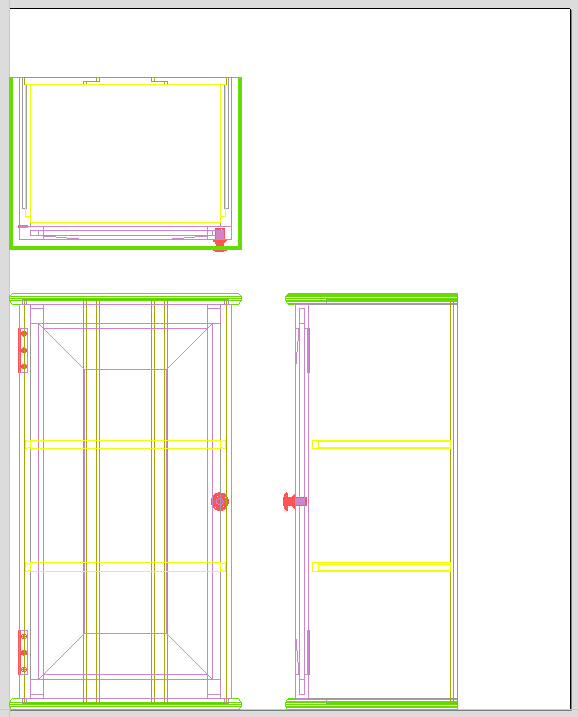
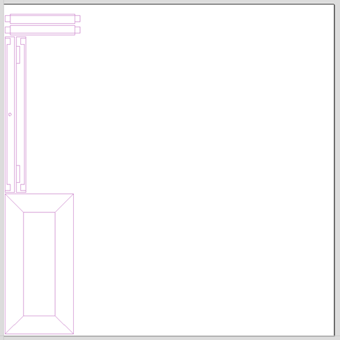
Three Views - Front, Top, Side
This option will create an 'engineering drawing' style layout of the SketchUp model as shown in the screenshot below.
The size of the model is preserved and it is relatively simple to pick up dimensions for parts you are going to manufacture from the various views. The colors of the lines you see are taken from the colors of the original SketchUp layers the various parts of the model are on.
Create Circles / Arcs
SketchUp does not maintain true arc or circle information for the boundaries of its parts. This is a problem when it comes to machining as the 'polygonal' SketchUp representation can give very poor machining results. For this reason, VCarve Pro offers the option to refit circles and arcs to imported data.
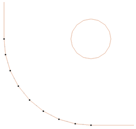
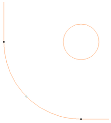
The screenshot above left shows the results of importing a part with a filleted corner and hole with these options unchecked. The 'fillet' is made up of a series of straight line segments and the circular 'hole' is actually a polygon made up of straight lines.
The screen shot above right shows the same part imported with both these options checked ✓. The 'fillet' now consists of a single smooth arc and the circular 'hole' now also consists of arcs rather than straight line segments. Both these features will machine more cleanly in this form.
Data to Import
A SketchUp model will often contain parts that you do not wish to machine (such as hinges, knobs etc.) or data which will be cut from different thicknesses of material and hence different parts need to be imported into different VCarve Pro jobs. To allow control over what is imported you can choose to only import parts of the model which are on particular layers using this section of the dialog.
To only import data from selected layers, choose the 'import visible data on selected layers' option and click the check box next to each layer to indicate if you want to import data from that layer. Note that the number of parts on each layer is displayed next to the layer name.
It is very easy to assign different parts of the model to different layers within SketchUp to help with the import process into VCarve Pro. The screenshot below shows the result of only importing data on the 'Door' layer from the example.
Component / Group Handling
This section of the form allows advanced handling of how 'parts' within the SketchUp model are identified and treated on import.
Group imported parts
This option is normally selected for all but the simplest models as it allows each 'part' of the model to be selected, moved and nested easily after import. You will need to ungroup the imported data after nesting etc. to allow individual features to be machined. By default, VCarve Pro will treat each SketchUp group / component as a single part UNLESS it contains other groups or components within it, in which case each lowest level group / component will be treated as a separate part.
Items which you retain in groups can be ungrouped at any time in the usual ways.
If the right-click menu-option to Ungroup back onto original object layers is used (which is the default option when using the icon or shortcut U) then the software will place the ungrouped items back onto the original layers they were created on in SketchUp.
Keep components starting with two underscores (__) together
If you have a complex model which contain 'parts' which are made up of other groups / components, you will need to do some work on your model to identify these parts for VCarve Pro. The way this is done is by setting the name of the groups / components that you wish to be treated as a single part to start with__ (two underscore characters). For example, if you had a model of a car and you wanted the wheels / tires / hub nuts to be treated as a single part even though the Tire, Wheel and other parts were separate components, you would group the parts together and name them something like __WheelAssembly in SketchUp. When this model was imported, and VCarve Pro reached the group/component with a name starting with __ it would treat all subsequent child objects of that object as being the same part.
Replace outer boundary (for flat jobs only!)
There is a style of 'building' with SketchUp where individual 'parts' are made up of several components 'butted' against each other. The screenshot below shows such a component.
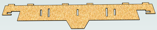
This object is made up of many smaller components representing the tabs on the top, the connectors at the end and the support at the bottom as shown below.
Although when can treat this as a single 'part' when imported by starting its name with __ (two underscores), the imported part is still going to be difficult to machine. The screenshot below shows the part imported into VCarve Pro without the 'Replace outer boundary' option checked ✓. The part in the image has been ungrouped and the central vector selected.
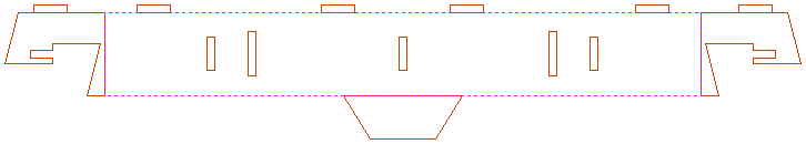
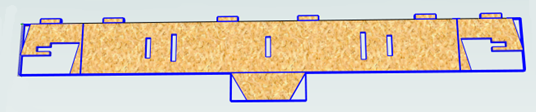
As you can see, the outer boundary is made up of separate segments for each 'feature'. VCarve Pro does have the ability to create an outer boundary for vectors but this can be time consuming if it has to be done manually. If the 'Replace outer boundary' option is checked, ✓ for every part VCarve Pro will try to create a single outer boundary and delete all the vectors which were part of this boundary. The screenshot below shows the result of importing the same data with this option checked, ✓ this time the part has been ungrouped and the outer vector selected.
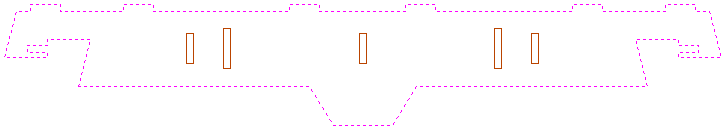
This data is now ready to be machined directly. It is important to understand the limitations of this option. It can be substantially slower. Creating robust boundaries for each part can consume a lot of processing power. Any feature which shares an edge with the boundary will be deleted. If the tabs on the top of this part were to have been machined 'thinner', this approach would not have been suitable as the bottom edge of the tabs has been removed.
IMPORTANT
The new features will help a lot of SketchUp users dramatically reduce the time it takes to go from a SketchUp design to a machinable part using Vectric Software. It is important to understand though that while these options provide a useful set of tools, in many cases there will still be additional editing required to ensure the part is ready to toolpath. Understanding the options and how they work will allow the part to be designed in SketchUp with these in mind and therefore help to minimize the time to machine once the data is imported.
Note
Sketchup files will only open in the same bit version you are running e.g. A file saved in a 32 bit version of Sketchup will only open up in a 32 bit version of the software.