Material Setup - Flat
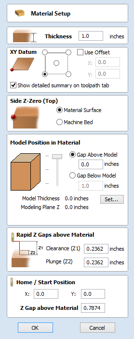
Thickness
Enter the thickness of the material being machined.
Show detailed summary on toolpath tab
This checkbox toggles the Material Setup summary layout on the Toolpaths tab between simple and detailed views.
Side Z-Zero
Select relative to the Material Surface or relative to the Machine Bed. This is a very important setting because the tooling used on the CNC machine must be setup in the same way, ensuring the toolpaths cut to the correct depth.
If you are working in a 2 Sided job, this will set the Z Zero for your current side only,
- The side you are setting up will be displayed in brackets e.g. (Top).
- You can set the Z-Zero for both sides through the Job Setup form.
Model Position in Material
The thickness of your model must be less than the thickness of the material you wish to cut it from. You can position your model within the material block wherever you wish by defining the gap distance either above or below your model. You can also double left click on either of the three lines next to the slider to position the model at the top, center or bottom of the material.
Note for Two-Sided Jobs
The gaps defined here are for the entire combined models from both sides (i.e. the final result you see when two-sided view is enabled). The above / below gaps do not depend on which side you are currently on. They represent the whole 2 sided model as if viewed in the correct orientation.
Gap Above Model
This distance positions your model according to the gap between the top of your model and the top surface of the material.
Gap Below Model
Alternatively you can position your model by defining the gap between the bottom of the model and the bottom surface of the material.
Model Thickness
This field simply reports the thickness of your composite model (as built from all your currently visible components).
Scale Model Height
The button can be used to change the Z Height of the Composite 3D Model (the visible Components) if it is not an appropriate height for your material thickness. Clicking this button will open the Set Model Height form which allows you to enter a new value for the overall height of the combined Components. After you have entered a new value hit and visually check the 3D model to ensure it still looks correct. Once you have found an appropriate value that looks good you can hit the button to continue in the Material Setup form. This height scaling function is also available from the Scale z height of model icon on the modeling toolbar.
Modeling Plane Z
Once you have positioned your model, this field will tell you the new height of your modeling base plane. This is for information only, and results from the gap settings above and cannot be edited directly.
Rapid Z Gaps above Material
Clearance (Z1)
This is the height above the job at which it is safe for the cutter to move at rapid or maximum feed rate. The software will raise the bottom of the cutter to this height when it traverses the material.
Plunge (Z2)
For all toolpaths, as well as specifying a rapid clearance gap for rapid positioning moves above the workpiece, the user can also specify a much smaller gap that the tool will rapid down to during plunge moves. By default the plunge gap is set to the same value as the Clearance gap which means that there will be no rapid plunges. If you set the plunge gap to a smaller value than the Clearance gap, the tool will plunge at rapid feed rate to the specified distance above the material surface before changing to the specified plunge rate. For jobs where a large value for Clearance gap has to be specified to avoid clamps etc, this feature can save a considerable amount of machining time if there are a lot of plunge moves in the job.
Note
Some engraving machines are not able to take advantage of this feature.
Home / Start Position
This is the absolute position that the tool will start moving from and where the tool can be programmed to return to at the end of cutting the job.