Toolpath Tiling Manager
Using the Toolpath Tiling options it is possible to machine objects and designs that are many times larger than the available area of your CNC machine bed. This process is also invaluable if the maximum size of your material pieces are limited. In both cases, a much larger project can still be achieved by breaking the toolpath down into manageable tiles or strips, each of which can fit within the machinable area of your CNC machine, or on the available material blocks. Once cut, the tiles can then be re-assembled to form the finished piece.
The process of tiling begins by creating toolpaths based on the final object entirely as normal - at this stage you do not need to take any account of the available machining bed size. Once you have calculated required toolpaths, click on the toolpath tiling button in the toolpaths pane to open up the toolpath tiling form.
Tiling Options
There are three layout strategies for tiled toolpaths, the most appropriate one will depend on your machines capabilities and the available material.
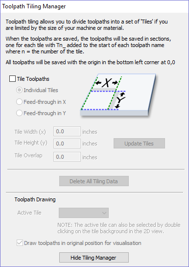
Individual Tiles
The first tiling option is for individual tiles. This splits the current job in both X and Y, to form a series of entirely separate toolpaths. This is generally the preferred option if you have independent pieces of material to machine, or if you have a moving-bed type CNC machine that will not allow you to 'overhang' material outside of the machinable area.
With this option selected, you are asked to specify the width and height of each tile, and the required overlap (which will be applied in each direction). Tiles are created from the bottom left of your model. The overlap for independent tiles is particularly important for 2.5D toolpaths that utilize the shape of your tool bit (such as V-bit carving). 2.5D toolpaths will need to 'overrun' the edges of your tile in order to complete their cuts using the side of the bit. For this reason, the overlap distance for Independent Tiles will typically need to be at least equal to the radius of your tool bit.
Feed-through in X or Feed-through in Y
Instead of cutting a series of individual pieces of material and assembling them later, it can also be convenient to cut a single strip of material using a series of set-ups - moving the material through the machinable area between cuts. Aspirespecifically supports this technique using the Feed-through in X/Y options. In these cases you will only need to define either the Tile Width or Height (which corresponds to your intended feed-through distance), as the other dimension is assumed to correspond to the shorter side length of your material and will match the equivalent current job dimension. Similarly, the overlap distance is only applied in the direction of the draw-through. Because you will typically be cutting the same piece of material with each toolpath tile, the overlap distance for Feed-through is not as critical as for Individual tiles and is typically used to allow for a margin of error in your set-up accuracy.
Once you have set your tiling option, click the Update Tiles button to see your settings reflected in the Tile Previews in either the 2D or 3D Views.
Machine smallest tile first
If this option is unchecked then the tiling space is divided into parts of the specified size. Any remainder space is placed at the end. If the option is checked then the remaining space is placed at the beginning.
Tile Previews
The 2D View indicates how the model area is split into tiles. The yellow lines indicate the tile sizes, but the light red areas also indicate the overlap region for each tile.
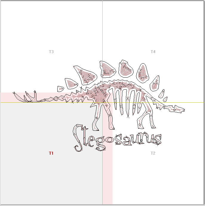
Double-clicking on a tile will make that tile the active tile.
In the 3D view the toolpaths will be showed tiled, with only the moves that are within the active tile shown.
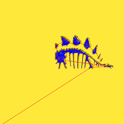
Simulating Tiled toolpaths
You can also view and simulate individual toolpath tiles in the 3D View. To view the toolpath tiles, simply ensure that the toolpaths are visible (checked ✓ in the Toolpath List) and then select the tile you wish to see either from the Tile Toolpaths form, or the 2D View (see above).
Since tiles are created so that they will all be cut within the same machinable area (i.e. they are all located in a similar position relative to the machining origin), this can make them difficult to visualize using Preview Toolpaths. Simulating each toolpath tile in its absolute position will result in the toolpaths being cut in the same region of your preview block and they will overcut the same area. The Tile Toolpaths form has an option Draw toolpaths in original position for visualization to allow you to simulate the tiles as if they were arranged in their final pattern. With this option enabled, you can visualize how your final piece will look by previewing all your toolpath tiles together, but you should note that it will not reflect the true offset of each toolpath from your machining origin.
Saving toolpath tiles
Provided you have created toolpath tiles using the Tile Toolpaths form, an additional option, Output Tiled Toolpaths, will be available in the toolpath saving form.
It will be checked ✓ or unchecked to match the current state of the Tile Toolpaths check box in the Tile Toolpaths form.