Chamfer Toolpath
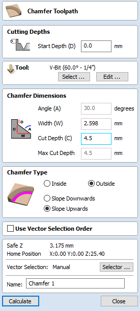
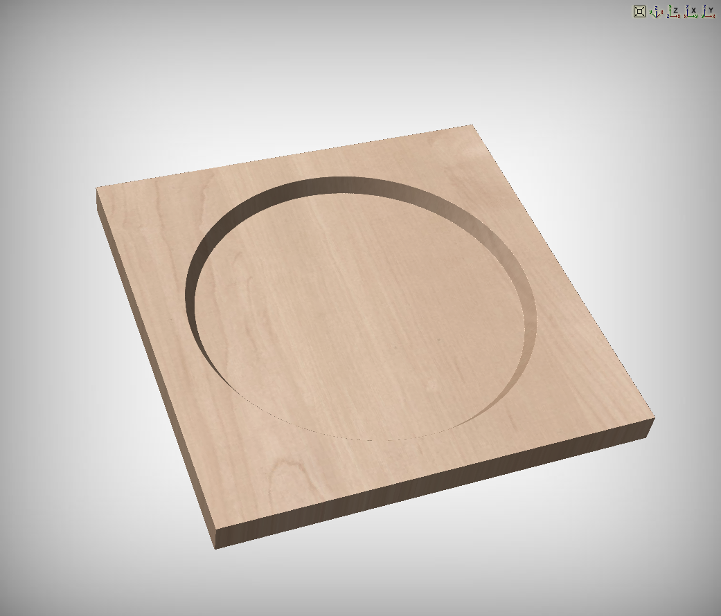
The Chamfer Toolpath uses the selected vectors and tool to create an angled feature
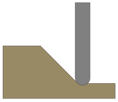
The Chamfer Toolpath has two distinct ways of operating depending on the tool used:
- If the selected tool is an angled tool, then the angle of the tool determines the angle of the chamfer
- If the selected tool is a round nosed tool, then the angle of the chamfer must be specified manually, and will be approximated by a series of fine cuts.
 Cutting Depths
The Start Depth (D) specifies the depth at which the top of the chamfer should start.
Vector Selection
To create the toolpath you must first draw and then select the vectors you wish to create the chamfer on.
Werkzeug
Wenn Sie die Schaltfläche klicken, wird die Werkzeugdatenbank geöffnet, aus der Sie das benötigte Werkzeug auswählen können. Lesen Sie für weitere Informationen hierzu den Abschnitt über die Werkzeugdatenbank. Wenn Sie auf die Schaltfläche klicken, öffnet sich das Formular "Werkzeug bearbeiten", über das Sie die Fräsparameter für das ausgewählte Werkzeug anpassen können, ohne die Master-Informationen in der Datenbank zu verändern. Wenn Sie mit dem Cursor über den Namen des Werkzeugs fahren, wird ein Tooltip eingeblendet, der den Ort in der Werkzeugdatenbank angibt, von dem das Werkzeug ausgewählt wurde.
Chamfer Dimensions
The chamfer dimensions control the shape of the created chamfer.
Angle (A)
The angle determines the slope of the chamfer. It is measured from vertical. For a V-Bit tool then the angle is fixed to half of the angle of the tool. For a round nosed tool then the angle may be specified.
Width (W)
The width determines the horizontal size of the chamfer. If the angle is set then changing the width will change the cut depth proportionally.
Cut Depth (C)
The Cut depth is the height of the chamfer. If angle is set then changing the cut depth will change the width proportionally.
Max Cut Depth
To achieve the desired height of the chamfer, as specified by the cut depth field, cutting deeper might be required. This will be true in the case of a round-nosed tool.
The Max Cut Depth field is read only and shows the full length of the cut so you can accurately see how deep the tool cuts.
Chamfer Type
The Chamfer Type option controls whether or not a chamfer occurs inside or outside a vector and the direction of the chamfer slope :
- An inner chamfer will be inside the selected vector.
- An outside chamfer will be outside the selected vector.
The direction of the slope tells us whether our chamfer is upward or downward relative to the selected vector or whether it is downward relative to the selected vector.
Both options can be used together to generate different chamfer styles.
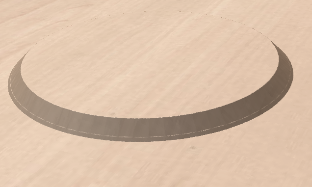
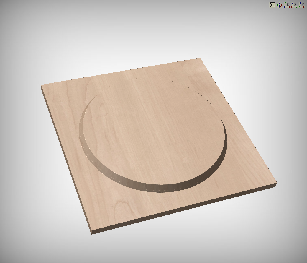
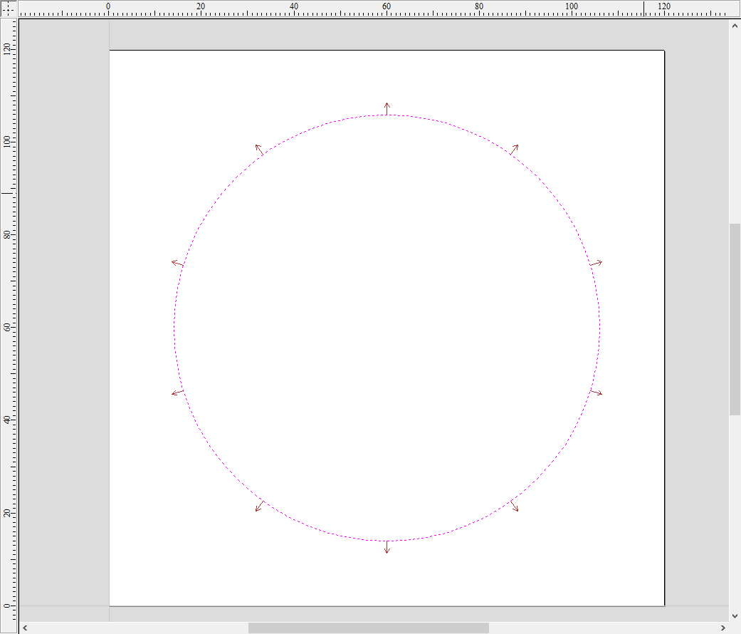
2D Preview
When using the Chamfer toolpath the 2D View will provide immeditate feedback on what the resulting chamfer will look like. Small lines will extend outwards from the selected vector to show where the slope of the chamfer will lie. The arrows on these line indicate the direction of slope. The arrows always point down in the direction of the downwards slope.
Vektor-Auswahlreihenfolge verwenden
Wenn diese Option ausgewählt ist, ✓ werden die Vektoren in der Reihenfolge bearbeitet, in der Sie diese ausgewählt haben. Ist die Option nicht ausgewählt, optimiert das Programm die Reihenfolge, um die Bearbeitungszeit zu reduzieren.
Positions- und Auswahleigenschaften
Sicherheits-Z
Die Höhe oberhalb des Werkstücks, in der Sie den Fräser sicher in hoher oder maximaler Geschwindigkeit fahren können. Diese Größe kann durch das Öffnene des Formulars zur Materialeinrichtung geändert werden.
Ausgangsposition
Die Position, zu der das Werkzeug vor und nach der Bearbeitung fährt. Dieses Maß kann durch das Öffnen des Formulars zur Materialeinrichtung geändert werden.
Vektorauswahl
In diesem Bereich der Seite "Werkzeugpfad" können Sie automatisch Vektoren auswählen, um das Werkstück mit den Eigenschaften oder der Position des Vektors zu bearbeiten. Auf diese Weise können Sie auch Werkzeugpfad-Vorlagen erstellen, um Ihre Werkzeugpfad-Einstellungen in Zukunft für ähnliche Projekte wieder zu verwenden. Weitere Informationen finden Sie in den Abschnitten Vektorwähler und Erweiterte Werkzeugpfad-Vorlagen.