Post Processor Editing
 What does the Post Processor Do?
The post processor is the section of the program that converts the XYZ coordinates for the tool moves into a format that is suitable for a particular router or machine tool. This document details how to create and edit the configuration files that customize the output from the program to suit a particular machine control.
Below are sections of a typical program that has been post processed into both G-Code and HPGL
G-Code Output
T1 M6
G17
G0 Z4.5000
G0 X0.0000 Y0.0000 S12000 M3
G0 X2.4567 Y7.8342 Z0.2500
G1 Z-0.0500 F5.0
G3 X3.3784 Y8.7559 I0.0000 J0.9218 F66.0
G3 X2.4567 Y9.6777 I-0.9218 J0.0000
G3 X1.5349 Y8.7559 I0.0000 J-0.9218
HPGL Output
IN;PA;
PU2496,7960;
PD2496,7960;
AA2496,8896,90.000
AA2496,8896,90.000
AA2496,8896,90.000
AA2496,8896,90.000
PU2496,7960;
PU2496,6096;
Machine controller manufacturers will often customize the file format required for programs to run on a particular machine in order to optimize the control to suit the individual characteristics of that machine.
The Vectric post processor uses simple text based configuration files, to enable the user to tailor a configuration file, should they wish to do so.
Post Processor Sections
Vectric post processors are broken down into sections to aid clarity, try to write your post processors in a similar style to aid debugging.
File Comments
A section where you can describe the post processor and record any changes to the post processor, each line is a comment and starts with a ‘+’ character or a ‘|’ character.
+ History
+ Who When What
+ ======== ========== ===========================
+ Tony 14/07/2006 Written
+ Mark 26/08/2008 Combined ATC commands, stop spindle on TC
+================================================
Global File Statements
Statements are items that are either used only once, or have static values throughout the file. Write statement names in upper case letters for clarity.
Statement | Result |
|---|---|
| The name that will appear in the post processor list |
| The file extension that the file will be given |
| The units that the file outputs (INCHES or MM) |
| The machine tool manufacturer has supplied a driver (usually a printer driver) thatn can directly accept the NC file output (For example see Generic HPCL_Arcs.pp) |
| Indicates that plunge moves to Plunge (Z2) height (that is set on the material setup form) are rapid moves |
| The control software uses a document interface that can directly accept the NC file output. |
| The moves in the Y axis are to be wrapped around a cylinder of the specified diameter. The "Y" values will be output as "A" |
| The moves in the X axis are to be wrapped around a cylinder of the specified diameter. The "X" values will be output as "B" |
| Spindle speed for this machine is output as a range of integer numbers between 1 and 15 representing the actual speed in RPM of the spindle, (between 4500 and 15000 RPM in the quoted example). For an example, see the file: Roland_MDX-40_mm.pp |
| This command allows you to substitute a character output within the variables (such as The characters are entered in pairs, Original - Subsititued. For example MACH 3 control software uses parentheses as comment delimiters, and does not allow nested comments. Most tools within the Vectric Tool Database have parentheses within the “Name” section; if these names are output, this would cause an error within Mach3. The command |
| Rotary: Enables / Disables output of the feedrate F in Inverse Time Feed Mode. In this mode, we're expected to complete a move in one divided by the F number of minutes. In GCode, this would G93 to switch on, or G94 to switch off and use units mode. |
| Indicates that this post-processor supports laser toolpaths (if the Laser Module is installed). |
Tape Splitting Support
A section that describes how a long toolpath output will be split:
TAPE_SPLITTING=MAX_NUM_LINES LINE_TOL "FILENAME_FORMAT" START_INDEX INDEX_ON_FIRST_FILE
For example a command of:
TAPLE_SPLITTING=1000 100 "%s_%s.tap" 1 "YES"
would lead to...
Output will be split into multiple files of a maximum of 1000 lines (+ however many lines in there are within the footer section of the post processor), if a retract move exists after line 900 (1000 – 100), the file will be split at that move. If the file was called "toolpath" the split files would be named toolpath_1.tap, toolpath_2.tap etc. The first toolpath output will be "toolpath_ 1.tap" there will be no file named "toolpath" without an index number, (as INDEX_ON_FIRST_FILE= YES is used), unless the file was less than 1000 lines long, in which case the file would not be split.
Note
Some controllers that require NC files to be split, also have limitations on the number of characters within a filename. For example they may require the file to be named with the MSDOS style 8.3 filename format. This should be considered when naming the output file.
Line Terminating Characters
LINE_ENDING="[13][12]"
Decimal values of the characters appended to each separate line of the post processed file. (Will usually be [13][10]) (Carriage return, line feed) for any controller that can read a windows or MSDOS format text file.
Block Numbering
If you wish to add line numbers to the output file, the current line number is added with the variable [N]. The behaviour of this line number variable is controlled by the following variables:
Statement | Result |
|---|---|
| Value at which the line numbering should start |
| Incremental value between line numbers |
| The maximum line number to output, before cycling to the Important - Some controllers have a limit to the number of lines that can be displayed on the control |
Variables
Variable Name | Output using | Value | Example File |
|---|---|---|---|
|
| Current Feed Rate. | Mach2_3_ATC_Arcs_inch.pp |
|
| Current Cut Feed Rate. | CNCShark-USB_Arcs_inch.pp |
|
| Current Plunge Feed Rate. | CNCShark-USB_Arcs_inch.pp |
|
| Current Spindle Speed in R.P.M. | GCode_arc_inch.pp |
|
| Current power setting for jet-based tools (e.g. lasers) | grbl_mm.pp |
|
| Current Tool Number. | Mach2_3_ATC_Arcs_inch.pp |
|
| Previous Tool Number. | NC-Easy.pp |
|
| Line Number. | Mach2_3_ATC_Arcs_inch.pp |
|
| Name of Current Tool. | MaxNC_inch.pp |
|
| Text from Note field in ToolDB for current tool | Busellato_Jet3006_arc_inch.pp |
|
| Name of Current Toolpath. | Viccam_ATC_Arcs_inch.pp |
|
| Filename (Produced by “Save Toolpath(s)”). | ez-Router_inch.pp |
|
| Folder Toolpath File was saved to. | Woodp_arc_mm.pp |
|
| Toolpath File Extension. | TekcelE_Arc_ATC_3D.pp |
|
| Toolpath Folder Pathname. | WinPC-NC_ATC_Arcs_mm.pp |
|
| Current coordinate of tool position in X axis. | GCode_arc_inch.pp |
|
| Current coordinate of tool position in Y axis. | GCode_arc_inch.pp |
|
| Current coordinate of tool position in Z axis. | GCode_arc_inch.pp |
|
| Current coordinate of tool position in A axis. | |
|
| Arc centre in X Axis (relative to last X,Y position). | Mach2_3_ATC_Arcs_inch.pp |
|
| Arc centre in Y Axis (relative to last X,Y position). | Mach2_3_ATC_Arcs_inch.pp |
|
| Arc centre in X Axis (absolute coordinates). | Isel_arc_mm.pp |
|
| Arc centre in Y Axis (absolute coordinates). | Isel_arc_mm.pp |
|
| Start position of an arc in X axis. | TextOutput_Arcs_mm.pp |
|
| Start position of an arc in Y axis. | TextOutput_Arcs_mm.pp |
|
| Mid-point of arc in X (absolute coordinates). | TextOutput_Arcs_mm.pp |
|
| Mid-point of arc in Y (absolute coordinates). | TextOutput_Arcs_mm.pp |
|
| Mid-point of arc in X (incremental coordinates). | TextOutput_Arcs_mm.pp |
|
| Mid-point of arc in Y (incremental coordinates). | TextOutput_Arcs_mm.pp |
|
| The radius of an arc. | Bosch_ATC_Arcs_mm.pp |
|
| The angle of an arc. | Generic HPGL_Arcs.pp |
|
| Home tool position for X axis. | CAMTech_CMC3_mm.pp |
|
| Home tool position for Y axis. | CAMTech_CMC3_mm.pp |
|
| Home tool position for Z axis. | CAMTech_CMC3_mm.pp |
|
| Safe Z Height / Rapid Clearance Gap. | EMC2 Arcs(inch)(*.ngc) |
|
| Diameter of cylinder that axis is wrapped around. | Mach2_3_WrapY2A_ATC_Arcs_mm.pp |
|
| Length of material in X. | Mach2_3_ATC_Arcs_inch.pp |
|
| Length of material in Y. | Mach2_3_ATC_Arcs_inch.pp |
|
| Length of material in Z. | Mach2_3_ATC_Arcs_inch.pp |
|
| Minimum value of material in X. | MaxNC_inch.pp |
|
| Minimum value of material in Y. | MaxNC_inch.pp |
|
| Minimum value of material in Z. | MaxNC_inch.pp |
|
| Maximum value of material in X. | MaxNC_inch.pp |
|
| Maximum value of material in Y. | MaxNC_inch.pp |
|
| Maximum value of material in Z. | MaxNC_inch.pp |
|
| Origin Position in X. | TextOutput_Arcs_mm.pp |
|
| Origin Position in Y. | TextOutput_Arcs_mm.pp |
|
| Z Zero Position, Table or Material Surface. | TextOutput_Arcs_mm.pp |
|
| X, Y Origin. | TextOutput_Arcs_mm.pp |
|
| List of tools used (In order of use). | Mach2_3_ATC_Arcs_inch.pp |
|
| List of toolpaths used in file (in order of use). | Mach2_3_ATC_Arcs_inch.pp |
|
| Toolpath Notes (Toolpath Control form). | Mach2_3_ATC_Arcs_inch.pp |
|
| File Notes (Edit > Notes). | Mach2_3_ATC_Arcs_inch.pp |
|
| File creation time. | Mach2_3_ATC_Arcs_inch.pp |
|
| File creation date. | Mach2_3_ATC_Arcs_inch.pp |
|
| Dwell time in seconds when drilling. | Mach2_3_Arcs_inch.pp |
|
| Name of the product used to output file, including version number. | |
|
| Tool diameter. | |
|
| Rotary: Current Inverse Time Rate | AvidCNC_WrapX2A_G93_inch.pp |
Format of Variables
Values for tool position, feed rates, spindle speeds etc. are inserted into the file using variables. Variables are used throughout the file; the variables are replaced with the current value for that item when the file is post processed. For example, the current X, Y and Z tool positions at any time, are inserted into the file by using the variable output, [X], [Y] and [Z] respectively.
Write variable names in upper case letters for clarity.
A Variable is formatted as follows:
VAR VARIABLE = [VO|WO|CS|VF|MX]
where
VO= Variable output for example X, XF or F.WO= When output, A=Always, C=Only when changed.CS= Character string output before value .VF= Value format, determines the format that the value is output with.MX= Multiplier Value.
A typical variable
1 | 2 | 3 | 4 | 5 | 6 | 7 | 8 | 9 | 10 | 11 | 12 | 13 | 14 | 15 |
|---|---|---|---|---|---|---|---|---|---|---|---|---|---|---|
|
|
|
|
|
|
|
|
|
|
|
|
|
|
|
VAR- This line is a Variable.- Variable Name.
- Equals Sign.
- Open Square bracket - (start of variable formatting parameters).
- Variable label - i.e. label that is substituted with the variable value.
- Vertical Bar - Parameter separator.
A= Always output value,C= Only output value when it changes- Vertical Bar - Parameter separator.
- Character string to print before variable value.
- Vertical Bar - Parameter separator.
- Optional Format Flags - for details see below.
- Value Format - units and number of decimal places to output.
- Vertical Bar - Parameter separator.
- Output multiplier - for details see below.
- Close Square Bracket - End of formatting parameters.
Formatting the Output Value
The values format string should be formatted as follows:
FORMAT_FLAGS FIELD_WIDTH DECIMAL_SEPARATOR DECIMAL_PLACES
The format flags are optional and only needed by a small number of controllers they will be described shortly.
Field Width The Field width represents the minimum number of characters that are output. The field width is usually set to “1” a value greater than 1 is typically only required if a controller expects to see a fixed number of characters for the value. If this is the case, a number greater than 1 can be entered. The number entered will ensure that that number of characters is output. The number that represents the field width includes the full floating-point number for the output value, (including the decimal separator character).
Decimal Separator The decimal separator character is almost always just a period character, but there are some controllers that expect to see a comma character. (For an example of a post processor that does not use a period character, see the file: Heidenhain_inch.pp)
Decimal Places The number of decimal places output following the decimal separator. The values are often set at 3 for controllers operating in Metric, or 4 for controllers operating in Inches.
Optional Format Flags
The output values can be further modified by using the optional format flags:
Flag | Function | Default (without flag) |
|---|---|---|
| Left Justify the output | Values are right justified |
| Prefix the value with '+' or '-' | Only negative values are prefixed |
| If value has fewer characters than the set minimum, the value is prefixed with zeroes | Values is prefixed with blanks spaces |
| Values is always output with a separator character ( in practive this would only change the output value if the value is set to output integer values only) | When output is set to integer only, separator charactor is not appended to value. |
Default Formatting For Variables
Most variables have a default format; (shown below) to set a different format for a variable, enter the line below in your post processor and alter the parameters to suit your controller.
Default | Example |
|---|---|
|
The line number will always be output. An 'N' character will be inserted before the line number. It will be output as an integer number |
|
The spindle speed will always be output. An 'S' character will be inserted before the value and it will be output as an integer number. |
|
The feed rate will be output with an F character before the value, and will only be output when it changes. The value will be output to 1 decimal place Note In this format string there is an option extra parameter. This is the value multiplier. |
VAR PLUNGE_RATE = [FP|A||1.0] |
The plunge rate will be output with an F character before the value, and will only be output when it changes. The value will be output to 1 decimal place. Note In this format string there is an option extra parameter. This is the value multiplier. |
|
The cut rate will be output with an F character before the value, and will only be output when it changes. The value will be output to 1 decimal place. Note In this format string there is an option extra parameter. This is the value multiplier. |
|
The position value will be output with an ‘X’ character before the value, the position will Always be output, and will be output to 3 decimal places, this would typically be suitable for a control that requires metric output. If you wished to output the values to 4 decimal places as would be more typical for a controller operating in inches. You would format the line as follows.
|
|
The home position value will be output with an ‘X’ character before the value, the position will Always be output, and will be output to 3 decimal places, this would typically be suitable for a control that requires metric output. If you wished to output the values to 4 decimal places as would be more typical for a controller operating in inches. You would format the line as follows.
|
|
The value will be output with an ‘X’ character before the value, the position will Always be output, and will be output to 3 decimal places, this would typically be suitable for a control that requires metric output. If you wished to output the values to 4 decimal places as would be more typical for a controller operating in inches. You would format the line as follows.
Note In this format string there is an option extra parameter. This is the value multiplier. |
|
The value will be output with an ‘Y’ character before the value, the value will Always be output, and will be output to 3 decimal places, this would typically be suitable for a control that requires metric output. If you wished to output the values to 4 decimal places as would be more typical for a controller operating in inches. You would format the line as follows.
|
|
The value will be output with a ‘J’ character before the value, the value will Always be output, and will be output to 3 decimal places, this would typically be suitable for a control that requires metric output. If you wished to output the values to 4 decimal places as would be more typical for a controller operating in inches. You would format the line as follows.
|
|
The value will be output with a ‘J’ character before the value, the value will Always be output, and will be output to 3 decimal places, this would typically be suitable for a control that requires metric output. If you wished to output the values to 4 decimal places as would be more typical for a controller operating in inches. You would format the line as follows.
Note In this format string there is an option extra parameter. This is the value multiplier. |
|
The value will be output with a ‘X’ character before the value, the value will Always be output, and will be output to 3 decimal places, this would typically be suitable for a control that requires metric output. If you wished to output the values to 4 decimal places as would be more typical for a controller operating in inches. You would format the line as follows.
|
|
The value will be output with a ‘R’ character before the value, the value will Always be output, and will be output to 3 decimal places, this would typically be suitable for a control that requires metric output. If you wished to output the values to 4 decimal places as would be more typical for a controller operating in inches. You would format the line as follows.
|
|
The value will be output with a ‘A’ character before the value, the value will Always be output, and will be output to 3 decimal places, this would typically be suitable for a control that requires metric output. If you wished to output the values to 4 decimal places as would be more typical for a controller operating in inches. You would format the line as follows.
|
|
The value will be output with an ‘X’ character before the value, the value will Always be output, and will be output to 3 decimal places. |
Multiplier Value
The multiplier value is used to multiply the value to output a different value. Common reasons for wishing to do this are:
To convert the default output of an Inch post processor, from inches per minute to inches per second, (Multiply by 0.01666).
To convert the default output of a Metric post processor, from mm per minute to mm per second, (Multiply by 0.0166).
To make positive values negative (and vice versa), (Multiply by -1).
To convert the output of an arc angle from radians to degrees, (Multiply by 57.2957795).
To multiply or divide by a fixed factor (I.E. produce 1:4 scale model, Multiply by 0.25)
Post Processor Blocks
HEADER
+---------------------------------------------------
+ Commands output at the start of the file
+---------------------------------------------------
begin HEADER
"Commands"
The header is the location for the instructions that are output once, at the start of the file, these generally setup modal commands for the controller.
For example, the Header might contain a command to display the filename on the controller and a series of “G-Codes” to set the machine up, for instance G20 to tell the control that the moves are in inches, or G21 to tell the control that the moves are in millimetres.
Variables that you might wish to be within the header section, could include:
Information about the Material Block
- Minimum extent in X = [XMIN]
- Minimum extent in Y = [YMIN]
- Minimum extent in Z = [ZMIN]
- Maximum extent in X = [XMAX]
- Maximum extent in Y = [YMAX]
- Maximum extent in Z = [ZMAX]
- Length of material in X = [XLENGTH]"
- Length of material in Y = [YLENGTH]"
- Depth of material in Z = [ZLENGTH]"
Home Position Information
- Home X = [XH]
- Home Y = [YH]
- Home Z = [ZH]
- Rapid clearance gap or Safe Z = [SAFEZ]
Details of the first tool to be used.
- Tool Number = [T]
- Tool name = [TOOLNAME]
Initial cutting speeds
- Feed Rate used for cutting and plunging into the material = [F]
- Feed Rate whilst tool is Cutting the material = [FC]
- Feed Rate whilst tool is plunging into the material = [FP]
Actual values depend on the UNITS set (see Global File Settings) Defaults are either MM/Minute or Inches/Minute, but the output can be changed to suit by setting the appropriate “VAR FEED_RATE” formatting.
Spindle Speed
- Spindle Speed = [S] R.P.M.
TOOLCHANGE
+---------------------------------------------------
+ Commands output at toolchange
+---------------------------------------------------
begin TOOLCHANGE
"Commands"
Commands that are output when a change of tool is required. Variables and commands that might be used include:
- Previous Tool Number = [TP]
- Tool Number = [T]
- Tool name = [TOOLNAME]
- Toolpath Name = [TOOLPATH_NAME]
- Toolpath Pathname = [PATHNAME]
- Toolpath File Name = [TP_FILENAME]
- Toolpath File Directory = [TP_DIR]
- Toolpath Extension = [TP_EXT]
- Spindle Speed = [S] R.P.M.
- M3 M Code often used to turn spindle on (Clockwise rotation).
- M5 M Code often used to turn spindle off.
NEW_SEGMENT
+---------------------------------------------------
+ Commands output for a new segment ( new toolpath with current toolnumber)
+---------------------------------------------------
begin NEW_SEGMENT
"Commands"
For an example of a NEW_SEGMENT section, see the file: Mach2_3_ATC_Arcs_inch.pp
Commands that are output when a new toolpath uses the currently selected tool, but perhaps a different spindle speed is required or the machine requires additional instructions.
Any commands that are used in the NEW_SEGMENT section should not need to be included within the TOOLCHANGE section as a tool-change will also automatically call the instructions in the NEW_SEGMENT section.
Variables that are commonly used include.
- Spindle Speed = [S] R.P.M.
- M3 M Code often used to turn spindle on (Clockwise rotation).
- M5 M Code often used to turn spindle off.
INITIAL_RAPID_MOVE
+---------------------------------------------------
+ Commands output for Initial rapid move
+---------------------------------------------------
begin INITIAL_RAPID_MOVE
"Commands"
For an example of a INITIAL_RAPID_MOVE section, see the file: Saom_OSAI_Arc_inch.pp
Commands that are output when the very first rapid move is made following the header or a tool change. A Section not used for most posts, but useful if the very first rapid move, needs to output different information to subsequent rapid moves. This section is sometimes required for HPGL variants.
RAPID_MOVE
+---------------------------------------------------
+ Commands output for rapid moves.
+---------------------------------------------------
begin RAPID_MOVE
"Commands"
Commands that are output when rapid moves are required.
FIRST_FEED_MOVE
+---------------------------------------------------
+ Commands output for first feed rate move in a series of feed moves.
+---------------------------------------------------
begin FIRST_FEED_MOVE
"Commands"
This section is commonly used where controllers require that the Feed Rate is set at the first feed move, this rate would then be used for subsequent cut moves.
For an example of a FIRST_FEED_MOVE section, see the file: Axyz_Arcs_ATC_inch.pp
FEED_MOVE
+---------------------------------------------------
+ Commands output for feed rate moves
+---------------------------------------------------
begin FEED_MOVE
"Commands"
Used to output information required at every move, or all feed moves except for the First Feed Move, if a FIRST_FEED_MOVE section is present within the post processor.
FIRST_CW_ARC_MOVE
+---------------------------------------------------
+ Commands output for the first clockwise arc move in a series of cw arc moves
+---------------------------------------------------
begin FIRST_CW_ARC_MOVE
"Commands"
Similar to the FIRST_FEED_MOVE section, but for clockwise arc segments. This section is commonly used where controllers require that the Feed Rate is set for the first arc segment, this rate would then be used for subsequent arc moves in the same direction.
For an example of a FIRST_CW_ARC_MOVE section, see the file: Centroid_Arcs_inch.pp
FIRST_CW_HELICAL_ARC_PLUNGE_MOVE
+---------------------------------------------------
+ Commands output for clockwise helical arc plunge move in a series of moves.
+---------------------------------------------------
begin FIRST_CW _HELICAL_ARC_MOVE
"Commands"
Similar to the FIRST_CW_ARC_MOVE section, but for moves that also move in Z. Feed rates output are from Plunge rate set for the tool.
For an example of a CW_HELICAL_ARC_PLUNGE_MOVE section, see the file: Mach2_3_ATC_Arcs_inch.pp
FIRST_CW_HELICAL_ARC_MOVE
+---------------------------------------------------
+ Commands output for clockwise helical arc move in a series of moves.
+---------------------------------------------------
begin FIRST_CW_HELICAL_ARC_MOVE
"Commands"
Similar to the FIRST_CW_ARC_MOVE section, but for moves that also move in Z.
For an example of a CW_HELICAL_ARC_MOVE section, see the file: Mach2_3_ATC_Arcs_inch.pp
CW_ARC_MOVE
+---------------------------------------------------
+ Commands output for clockwise arc moves.
+---------------------------------------------------
begin CW_ARC_MOVE
"Commands"
Similar to the FEED_MOVE section, but for clockwise arc segments.
For an example of a CW_ARC_MOVE section, see the file: Centroid_Arcs_inch.pp
CW_HELICAL_ARC_MOVE
+---------------------------------------------------
+ Commands output for clockwise helical arc moves
+---------------------------------------------------
begin CW_HELICAL_ARC_MOVE
"Commands"
Similar to the CW_ARC_MOVE section, but for moves that also move in Z.
For an example of a CW_HELICAL_ARC_MOVE section, see the file: Mach2_3_ATC_Arcs_inch.pp
FIRST_CCW_ARC_MOVE
+---------------------------------------------------
+ Commands output for the first counter-clockwise arc move in a series of ccw arc moves.
+---------------------------------------------------
begin FIRST_CCW_ARC_MOVE
"Commands"
Similar to the FIRST_FEED_MOVE section, but for counter-clockwise arc segments. This section is commonly used where controllers require that the Feed Rate is set for the first arc segment, this rate would then be used for subsequent arc moves in the same direction.
For an example of a FIRST_CCW_ARC_MOVE section, see the file: Centroid_Arcs_inch.pp
FIRST_CCW_HELICAL_ARC_PLUNGE_MOVE
+---------------------------------------------------
+ Commands output for counter- clockwise helical arc plunge move in a series of moves.
+---------------------------------------------------
begin FIRST_CCW_HELICAL_ARC_MOVE
"Commands"
Similar to the FIRST_CCW_ARC_MOVE section, but for moves that also move in Z. Feed rates output are from Plunge rate set for the tool.
For an example of a CCW_HELICAL_ARC_PLUNGE_MOVE section, see the file: Mach2_3_ATC_Arcs_inch.pp
FIRST_CCW_HELICAL_ARC_MOVE
+---------------------------------------------------
+ Commands output for first counter-clockwise helical arc move in a series of moves.
+---------------------------------------------------
begin FIRST_CCW_HELICAL_ARC_MOVE
"Commands"
Simile alla sezione FIRST_CCW_ARC_MOVE, ma relativa agli spostamenti eseguiti anche in Z.
Per un esempio di una sezione CCW_HELICAL_ARC_MOVE, vedere il file: Mach2_3_ATC_Arcs_inch
CCW_ARC_MOVE
+---------------------------------------------------
+ Commands output for counter-clockwise arc moves.
+---------------------------------------------------
begin CCW_ARC_MOVE
"Commands"
Similar to the FEED_MOVE section, but for counter-clockwise arc segments.
For an example of a CCW_ARC_MOVE section, see the file: Centroid_Arcs_inch.pp
CCW_HELICAL_ARC_MOVE
+---------------------------------------------------
+ Commands output for counter-clockwise helical arc moves
+---------------------------------------------------
begin CCW_HELICAL_ARC_MOVE
"Commands"
Similar to the CCW_ARC_MOVE section, but for moves that also move in Z.
For an example of a CCW_HELICAL_ARC_MOVE section, see the file: Mach2_3_ATC_Arcs_inch.pp
FOOTER
The footer is the section of the post processor for instructions that are sent to the controller at the end of a file. These might be instructions to return the tool to the home position, switch the spindle off or switch the power off to the drives.
+---------------------------------------------------
+ Commands output at the end of the file
+---------------------------------------------------
begin FOOTER
"Commands"
Variables that are commonly used include.
- G00 [XH] [YH] [ZH] Rapid to X,Y,Z Home position.
- M05 M Code often used to turn spindle off.
- M30 M Code often used to signify the end of the file.
Jet Support Sections
These sections are for supporting jet-based cutting tools such as lasers, plasmas and waterjets.
JET_TOOL_POWER
+---------------------------------------------------
+ Commands output when the cutter's power is set
+---------------------------------------------------
begin JET_TOOL_POWER
"Commands"
For an example of a JET_TOOL_POWER section, see the file: Grbl.pp
Commands that are output when the power setting associated with a laser 'tool' is issued.
JET_TOOL_ON
+---------------------------------------------------
+ Commands output when the cutter's power is turned ON
+---------------------------------------------------
begin JET_TOOL_ON
"Commands"
For an example of a JET_TOOL_ON section, see the file: Grbl.pp
Commands that are output when the jet tool is powered on. This is broadly equivalent to SPINDLE_ON, but is typically issued a the end of a plunge move when the jet cutter is already at the intended cutting height, instead of before the plunge move as required by a spindle based cutter.
JET_TOOL_OFF
+---------------------------------------------------
+ Commands output when the cutter's power is turned OFF
+---------------------------------------------------
begin JET_TOOL_OFF
"Commands"
For an example of a JET_TOOL_OFF section, see the file: Grbl.pp
Commands that are output when the jet tool is powered off.
Other Less Frequently Used Sections
FEED_RATE_CHANGE
+---------------------------------------------------
+ Commands output when feed rate changes
+---------------------------------------------------
begin FEED_RATE_CHANGE
"Commands"
For an example of a FEED_RATE_CHANGE section, see the file: Gravograph_IS200.pp
Commands that are output when the feed rate is changed. This section is not often used as many controllers will accept feed rate changes appended to other instructions, but sometimes used with HPGL variants.
FIRST_PLUNGE_MOVE
+---------------------------------------------------
+ Commands output for the First Plunge Move, in a series of plunge moves.
+---------------------------------------------------
begin FIRST_PLUNGE_MOVE
"Commands"
For an example of a FIRST_PLUNGE_MOVE section, see the file: Holz-Her_7123_ATC_Arcs_mm.pp
This section is often used on machines that do not fully support simultaneous 3D movement, for example the Z Axis cannot travel as fast as the X & Y Axis. Another use of this section might be to include commands that you wish to output whenever the first plunge move occurs. For example, commands to switch on a plasma torch. Multiple plunges would normally only be output within a ramping move, so this command would be useful for controls that automatically rapid between cuts and where instructions such as revised speeds and feed need to be specified on the first plunge move and these instructions are not required for subsequent plunge moves within the ramping operation.
PLUNGE_MOVE
+---------------------------------------------------
+ Commands output for Plunge Moves
+---------------------------------------------------
begin PLUNGE_MOVE
"Commands"
For an example of a PLUNGE_MOVE section, see the file: Burny_arc_inch.pp
This section is often used on machines that do not fully support simultaneous 3D movement, for example the Z Axis cannot travel as fast as the X & Y Axis. Another use of this section might be to include commands that you wish to output whenever a plunge move occurs. For example, commands to switch on a plasma torch.
RETRACT_MOVE
+---------------------------------------------------
+ Commands output for Retract Moves
+---------------------------------------------------
begin RETRACT_MOVE
"Commands"
For an example of a RETRACT _MOVE section, see the file: Burny_arc_inch.pp
A use of this section might be to include commands to switch off a plasma torch.
DWELL_MOVE
+---------------------------------------------------
+ Commands output for Dwell Commands
+---------------------------------------------------
begin DWELL_MOVE
"Commands"
For an example of a DWELL_MOVE section, see the file: Mach2_3_Arcs_inch.pp
This command was introduced for VCarve Pro 7.5 and Aspire 4.5 and later. It is used with a drilling toolpath, when a Dwell time has been specified in the program. If this section is not defined any dwell commands are ignored, but the rest of the drilling toolpath will be output as normal. The DWELL variable is documented in the Variables section.
Special Characters
Most characters can be output within the confines of the post processor output statements; however, certain characters have special meaning within the post processor configuration files and cannot be output directly.
These are, the Square brackets [ ], and the double quote character “ It may be the case that you need to output one of these characters within your output file.
If you wish to output one of these characters, you can do so by enclosing the decimal equivalent of the ASCII value of the special character that you wish to output, within square brackets, as shown below. This method can also be used to insert any ASCII value, even non-printable characters.
- [91] Outputs a left hand square bracket.
- [93] Outputs a right hand square bracket.
- [34] Outputs a double quote character.
- [13] Outputs a carriage return.
- [10] Outputs a line feed.
For an example of a file that uses special characters, please see: Biesse_Rover_Arcs_mm.pp
Example: Adding Tool-Change Commands
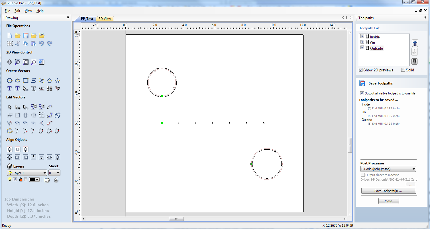
For the majority of cases, the quickest and easiest way of producing a customised post processor to suit your controller, will be to edit an existing post processor. To do this, first create a simple test file that you can use to test the output of your post processor. A simple file might consist of a line, and two circles. Produce a shallow cutting profile toolpaths for each of the shapes, machining “On” the line, “Inside” one of the circles and “Outside” the other circle.
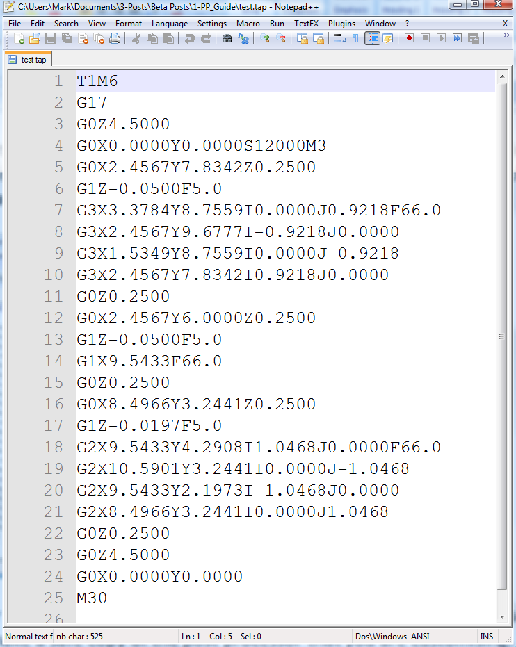
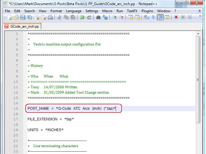
Save a toolpath using your base post processor and take a look at it using your favourite text editor. Below is an example of the test file posted using the "G-Code Arcs (inch) (*.tap)" post processor The example below is displayed using the popular Notepad ++ editor.
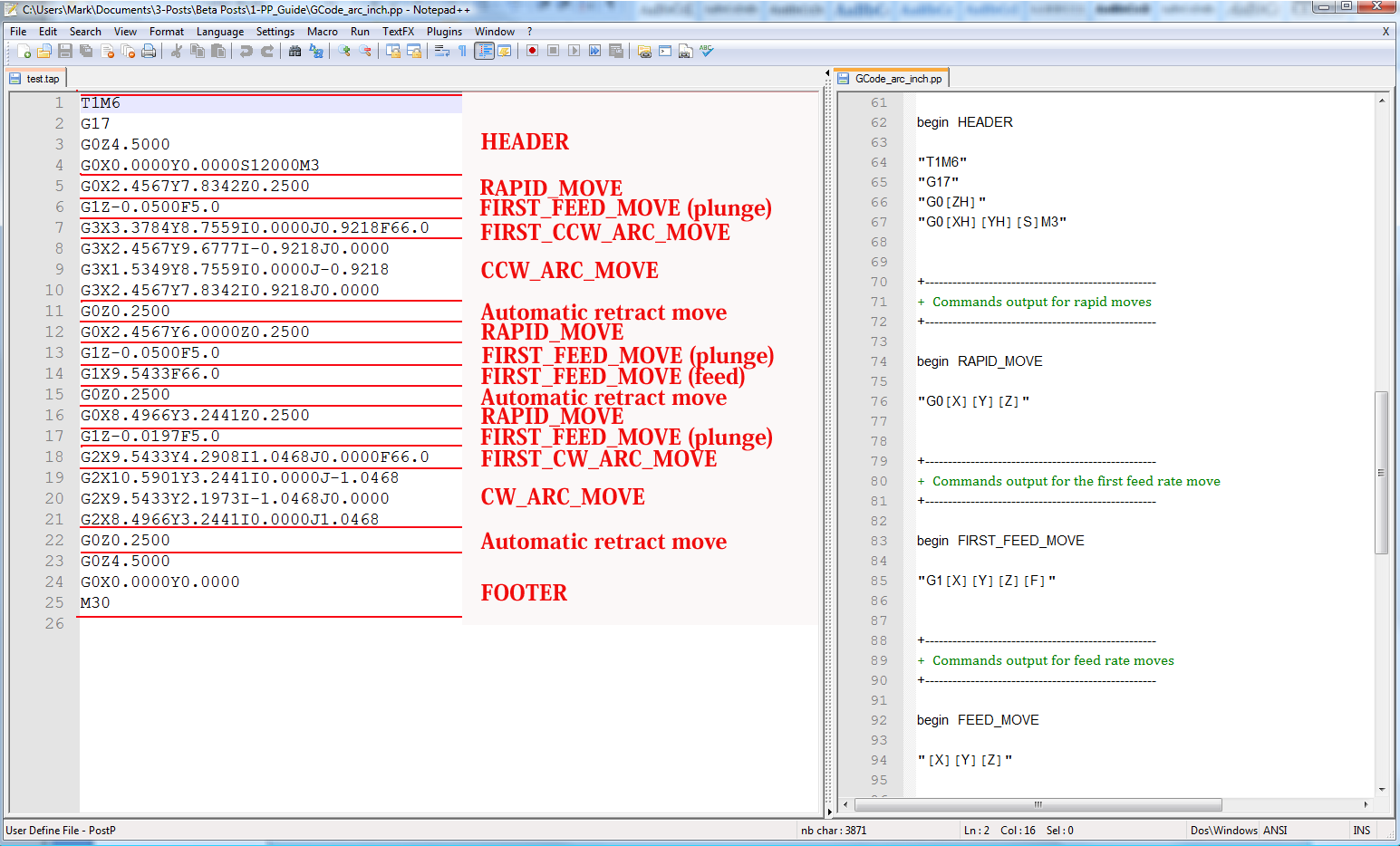
For our example, we will add a tool-change section to this post processor. First, make a safe copy of the post processor that you are customising. If you open the post processor that you are editing in a text editor, you will be able to see the lines of text within the post processor that formatted the output of your test file.
The PostP folder can be reached from within the application, by clicking “File > Open Application Data Folder” from the main menu of the application.
To add a Tool Change section to the post processor, you will need to consult the documentation for the control of the machine tool (or control software). For this example, we will assume that the instructions that you need to add to perform a tool change for your particular machine tool are as follows:
- M05 Instruction to turn off the spindle prior to tool change.
- M0 Instruction to return existing tool to tool holder.
- M06TTool_Number n Instruction to select new tool Tool_Number n
- G43HTool_Number n Instruction for control to use Tool length offset for tool n
- Sxxx M03 Set spindle speed to xxx; Turn on spindle (clockwise rotation).
Edit the post processor using your favourite text editor.
If the operating system on your computer is Microsoft Vista and User Access Control is enabled, copy or move the Post Processor that you are editing from the PostP folder to a folder below your user area.
The first thing that you should edit within the file is the History Comment section; So that you have a record of the changes.
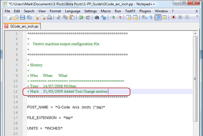
Next edit the POST_NAME to reflect that this post processor outputs automatic tool change (ATC) commands, the new post will be displayed as “G-Code ATC Arcs (inch)(*.tap)” in the list of post processors.
Next add a Tool Change Section that will include the instructions. The location of the new section within the file is not important, but a good place to insert it is between the Header and Rapid Move sections.
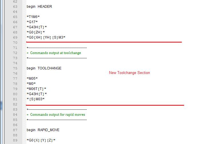
Add some comment lines at the top of the new section, (beginning with the + character) to describe the section and make the file as a whole, easier to read. Next enter the line “begin TOOLCHANGE” to instruct the post processor that the following instructions are to be output for every tool-change, (except the initial tool selection, the commands for these are contained within the header section).
The next step is to enter in the instructions that you require, enclosed within double quote marks. The “[T]” on the third and fourth instruction lines of our example, will be substituted with the tool number when the file is post processed; The “[S]” on the fifth line will be substituted with the spindle speed for the tool.
Finally you will need to save the changes to the file, as you have changed the POST_NAME, save the file using a new name, for example “GCODE_ATC_Arcs_inch.pp”
If the operating system on your computer is Microsoft Windows 7 or Microsoft Vista and User Access Control is enabled, copy the file that you have edited back to the “PostP” folder.
To test the new post processor, If the software is running, restart the software.
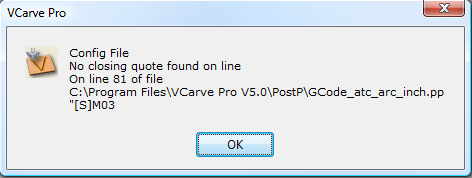
If there are any syntax errors with your post processor, an error similar to the picture below will be displayed as the software starts, the post processor that you have edited will not appear in the drop down list of post processor configuration files. You will need to rectify any errors and restart the software.
If there are no errors displayed when the software is started, open your test file and save one or more of your test toolpaths.
Select the post processor from the drop down list of post processor configuration and press the “Save Toolpath(s)” button.
Take a look at the file that you have just saved in a text editor.
If the content of the file looks good, try the file on your machine.
Please take all necessary precautions when running the output from a modified post processor for the first time.
Example: Changing the File Extension
The File extension that is automatically produced by the post processor can be changed within the “Save As” dialog box, when you click on the “Save Toolpath(s)” button.
However, rather than change the file extension every time. It is more convenient to permanently change the file extension produced by the post processor.
To do this:
Make a safe copy of the post processor that you wish to edit.
The post processor configuration files are located in the “PostP” folder of the product installation folder and have a “.PP” file extension. For Aspire version 2, the default location of the PostP folder is: “C:\Program Files\Aspire V2.0\PostP” the location of the PostP folder will be different depending on the product installed and whether the software was installed to a custom location when the software was installed.
Edit the post processor using your favourite text editor.
If the operating system on your computer is Microsoft Windows 7 or Microsoft Vista and User Access Control is enabled, copy or move the Post Processor that you are editing from the PostP folder to a folder below your user area.
Look for the following two lines within the post processor configuration file that begin with:
POST_NAME =
FILE_EXTENSION =
and alter these accordingly.
For example, if you wished to change the file extension produced by the “G Code ATC (inch)(*.tap)” post processor from “.tap” to “.nc”. Then edit the lines:
POST_NAME = "G Code ATC (inch) (*.tap)"
FILE_EXTENSION = "tap"
to make them read:
POST_NAME = "G Code ATC (inch) (*.nc)"
FILE_EXTENSION = "nc"
Save the changes to your file. If the operating system on your computer is Microsoft Windows 7 or Microsoft Vista and User Access Control is enabled, copy the file that you have edited back to the “PostP” folder.
To test the new post processor, If the software is running, restart the software. If there are any syntax errors with your post processor, an error similar to the picture below will be displayed as the software starts, the post processor that you have edited will not appear in the drop down list of post processor configuration files. You will need to rectify any errors and restart the software.
If there are no errors displayed when the software is started, open your test file and save one or more of your test toolpaths.
Select the post processor from the drop down list of post processor configuration and press the “Save Toolpath(s)” button.
Take a look at the file that you have just saved in a text editor.
If the content of the file looks good, try the file on your machine.
Please take all necessary precautions when running the output from a modified post processor for the first time.
Tips And Tricks
- Always make a safe copy of the post processor that you are editing, in case you need to start again from scratch.
- If using a word processor program, such as Microsoft Word, to edit a post processor, make sure that the file is saved as plain text. The file should not contain formatting information.
- If editing post processors on a computer that runs Microsoft Windows 7 or Microsoft Vista, do not edit the files directly within the “Program Files\Product folder\PostP” folder. Always edit the file within your user area and copy the edited file to “Program Files\Product folder\PostP”.
- Use comments when you make changes, a comment is a text that follows a + or a | character. Comments will not be acted upon by the program but can help in documenting changes that you have made and make those changes understandable in the future.
- All Instruction lines must be contained within quote marks.
- If possible, use a text editor that makes use of line numbers; This will make it easier to debug the post processor if there are any errors in the file. The program will check the post processors in the PostP folder when the program starts. If syntax errors are present in the file, an error message will be displayed, showing the line number of the first error encountered.
- Once you have successfully edited a post processor, make a safe copy of it. If you install a later version of the Vectric product that you are using, remember to copy your modified post processor to the PostP folder of the new version of the software. And select your modified post processor, the first time that you save a toolpath, (The software will remember your selection for subsequent actions).
- If you install another version of the software or you upgrade the version of the software, remember to copy your safe copies of your edited post processors to the PostP folder of the new version. Ensure that you select the correct post processor the first time that you post process a file using the new version of the software.
- For later versions of the software, ( V5.5 and above). The post processors should be accessed from within the application, by clicking “File > Open Application Data Folder\PostP folder.
- A customized list of post processors can be created by copying only the post processors required to the “File > Open Application Data Folder\My_PostP folder. If any file with a .pp file extension exists in the “My_PostP” folder, then only the post processors that exist in the My_PostP folder will be displayed in the drop down list of post processors.