What's New in Aspire V11
インターフェイス |
作図 |
モデリング |
工具経路 |
インターフェイス
Multiple Sheet Support
Version 11 makes the management of sheets, and the use of sheets to divide up your work a much more central part of the software's workflow:
- The new sheets tab lists all of the current sheets and allows you to create, update, and delete them.
- Sheets of different sizes, thicknesses, and even machine settings can be used.
- Sheets can be managed individually, or collectively, making it simple to resize or update a specific collection of sheets
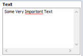
Spell Checker
Spelling errors will be underlined in red in the Create Text Form. right-click menu. Suggestions for corrections are shown on the right click menu, and can be selected to automatically replace the incorrect word. Additional words can also be added to the dictionary using the right click menu.
Swap Sides in 2-Sided Jobs
In two-sided jobs the new option to swap sides found in the Edit menu will swap the content from one side of the job to the other.
Online Post-Processor & Machine Management
Starting with Version 11 it will be possible to add and configure different machines through the Machine Configuration Management dialog. Each machine can have a set of post-processors defined, and separate feeds and speeds in the tool database, so that machine settings, post-processors, and tool feeds and speeds can be kept in sync.
Post-Processors can now be updated independently of the software using our online post-processor database. This can be accessed through the new Machine menu.
There is also the opportunity to get up and running quickly with a particular machine by using our Kickstarter Wizard which runs on first use, or later through the Online Search dialog, to help you choose the right post-processor, and the right tool database.
作図
Delete Multiple Layers
Within the layers right-click menu it is now possible to choose to delete multiple layers. There are options to delete 'Visible', 'Invisible' and 'Empty' layers!
Resize Vectors Individually
The set size form has been updated to allow the possibility of resizing a selection of vectors individually. Whereas previously all selected vectors were resized as part of a single transformation, they can now be treated as individual vectors. Each object in the selection can either be:
- Resized absolutely. This sets the size of each vector to the specified value. This might be useful for geometry that has to be a specific size, e.g circles, or slots.
- Resized by Percentage. This resizes the selected object by the specified percentage.
Text Kerning - Whole Line
Added the ability to adjust the kerning of an entire line by pressing while clicking between the letters.
モデリング
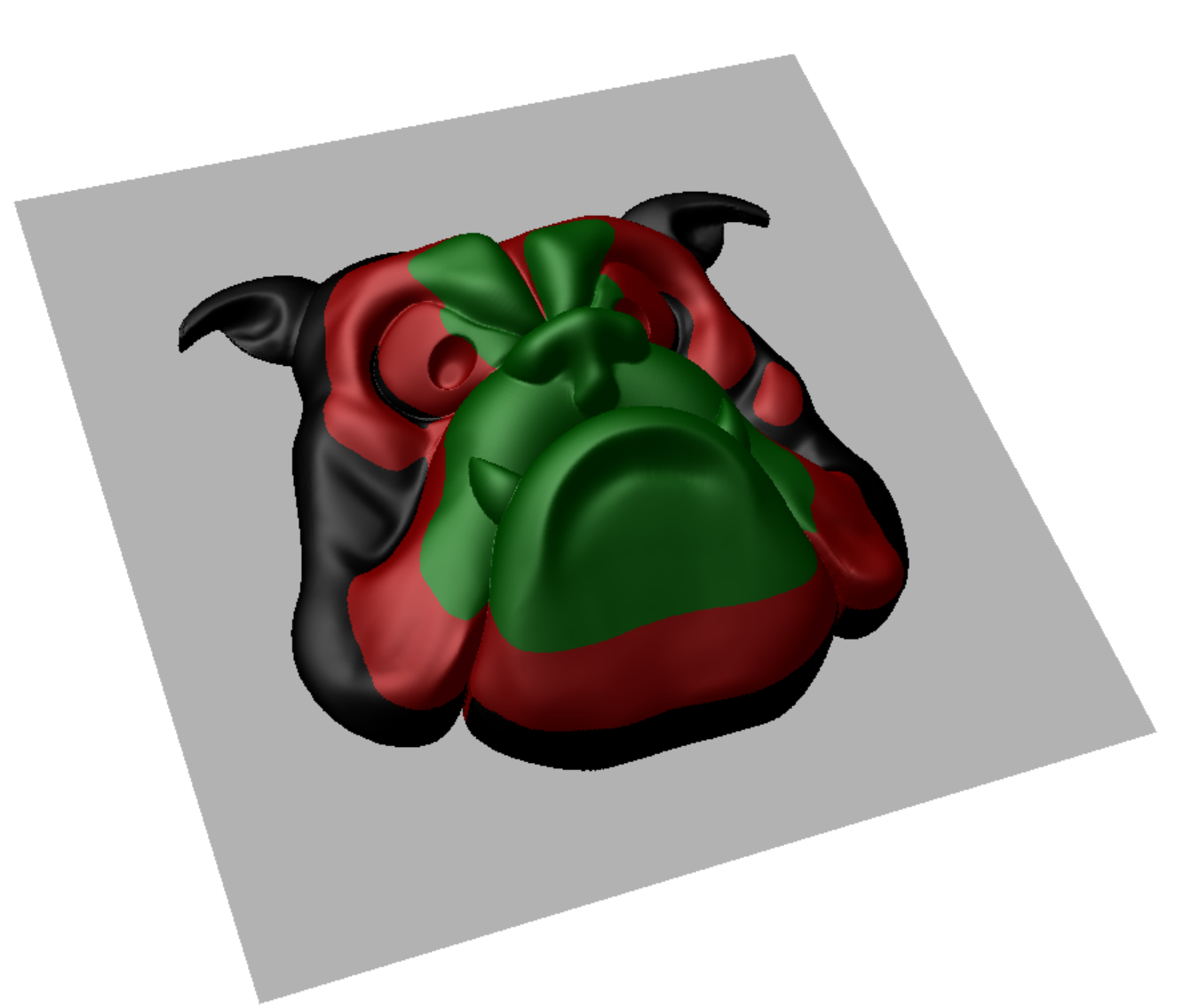
Component Brush Sculpting
It is now possible to use any model as a brush for sculpting. This brush will leave an impression in the model that simulates the pushing of the model through the surface. This technique can be used to add detail and texture to models.
3D Import Segmenting
When importing 3D models we've added a new tool to make it possible to segment the model in full 3D. This slicing tool makes it simple to dynamically choose both the thickness and orientation of the individual slices. Each individual slice can be chosen to ensure that undercuts are minimized. The slices can be easily visualized, both individually, and in layout mode so you can view what the resulting job will look like.
Variable Thickness Relief Slicing
The relief slicing feature has been extended to make it possible to choose the sizes of individual slices. Slice thicknesses can be tweaked and visualized in the 3D view to ensure that there are no thin slices. The resulting slices should be simpler to machine and assemble.
Highlight Undercuts Imported 3D Model
When Importing a 3D Model and positioning it, you can now highlight the undercuts directly from the Import 3D Model Dialog.
Re-Import 3D Models
Once a 3D model has been imported it is now possible to reimport that model if you want to adjust its sizing, position, or even re-segment it using the new Segmenting feature (Aspire only).
To reimport right-click on the the component from within the software to take you back to the model orientation form where the software will remember the last used settings.
Create Shape - Custom Profile
A custom profile can now be used for shape creation. This custom profile will behave similarly to the other pre-provided profile options, allowing you to control how the created shape is built up. This addition provides more control over the cross section of constructed shapes.
Create Shape - Sweep
The new Sweep option in the Create Shape form will take the chose profile (either one of the pre-provided, or a new custom profile), and sweeps the vector inside of any selected closed vectors. Used in conjunction with the custom profile options it can be used to create complex custom shapes with decorative boundaries.
工具経路
Rest Machining for Finish Toolpaths
Rest machining is a technique which uses multiple tools to try and optimize for machining time, material removal, and tool lifetime. A series of tools can be chosen, and the finish toolpath will use them from largest to smallest, with each tool removing any remaining material that the previous tool was unable to machine. The technique can be controlled by specifying parameters which determine what areas are worth machining with the smaller tool.
3D Roughing - Avoid Machined Areas
The 3D strategy in the Rough Machining Form now has the option to Avoid machined areas. This will mean that if an area has already been machined by a previous pass, then the current pass will try to not remachine this area. For some types of 3D model this will result in shorter machining times.
Chamfer Toolpath - Overcut & Cut Direction
The chamfer toolpath has two new features:
When using a V-bit tool for chamfering it can be desirable to use the edge of tool, and keep the point of the tool off the part. Small movements in the machine and the material can mean that the point of the tool leaves an unsightly witness mark. Using the new offset feature in the chamfer toolpath ensures that the toolpath always uses the side of the tool, and keeps the point away from the sharp chamfered edge.
It is also now possible to choose whether to use climb or convention when using the chamfer toolpath.
Moulding Toolpath Templates
The Moulding Toolpath Form can now use a pair of vector selectors to automatically select the vectors for machining. This also means it is now possible to save moulding toolpaths as toolpath templates, making their creation easily automatable.
3D Roughing - Raster Angle
The 3D roughing form now has the option to specify a specific raster angle. This can be useful if rastering along one of the principal axes would result in excess material left on for the finishing toolpath.
Ramping on VCarve End Mills
The VCarve Toolpath allows you to use a series of area clearance tools to help remove excess material. It is now possible to set these tools to ramp in rather than plunge. This reduces the chance of tool breakage, and can reduce wear and tear on the tool.